Search the Community
Showing results for tags 'stealthburner'.
-

Version 1.2.5
48,438 downloads
The Mini Stealth v2 toolhead is up on GitHub now. I will keep these files here as the new parts are not compatible with the v1.2.5 parts. I will support both versions in the comments here. I still need to create new assembly instructions but a lot of the steps are similar to what is described here. --------------------------------------------------------------------------- This toolhead scales down the body of the Stealthburner to a size which fits into a V0.1/V0.2. Fully assembled it weighs about 110 grams less than the original. It is designed around the Orbiter 2.0 extruder and has versions for the Phaetus Dragonfly, Dragon and Rapido HF hotends as well as versions for the Mosquito, the Revo Voron and the Creality Spider Pro hotends. It incorporates a status LED as well as two for print visibility. I have added new stretched versions that should fit the Rapido UHF, Dragon UHF and the VolcoMosq hotends. The Dragon UHF and Rapido UHF hotends can fit in the same shroud. The UHF hotends will reduce Z travel by 8.5mm and the VolcoMosq by 3mm. I cannot verify the fitment so if there are any issues please leave a comment. There are now two hex pattern inlays based on the design by 3DP-MAMSIH and a tutorial on how to apply them to the shroud. The negative body feature of Prusa/Super Slicer can also be used to create a crop-top version of the shroud as described at the end of the tutorial. The Mini Stealth uses a pair of 4010 blowers which produce more airflow than a 5015 blower while being notably less noisy and drawing less current. The depth of these fans do limit Y travel by 3mm on a V0.1 while the door is closed and tophat is on. The width of the main body at its base is also a very tight fit at the extremes of X travel. I have raised my tophat by 20mm which gives the cabling and filament tube plenty of room to breathe. The shroud fits a 3010 hotend fan or a 3007 fan by using a clip-in adapter. This Orbiter 2.0 Mini Stealth is a better fit than the Orbiter 1.5 Mini Stealth in a V2.4 or Trident as the motor no longer interferes with the path of the cable chain. There is a separate 'strain_relief' stl for use in the V0.1. There are also x-frame pieces that allow this Mini Stealth to be installed on a Switchwire. The nozzle is moved up by 3mm compared to the official Switchwire due to the stepper motor being so low on the Orbiter extruder but this also allows a BL-Touch to fit into the x-frame pieces. I have included a magnet mount and additional shroud .stl files to make this compatible with the ZeroClick mod. This toolhead also has versions that allow mounting a differential IR sensor. I have removed the mechanical Z endstop on my V0.1 and use the IR probe as an endstop and it has greatly simplified my homing sequence. There are additional x-frame pieces that allow mounting the Beacon3D probe, Euclid or Biqu MicroProbe for a V2.4, Trident or Switchwire. The included Blender file shows the entire assembly complete with screws and should answer most basic questions. Note on MGN-9 installation: The default 2mm x 10 plastic threading screw is too long for mounting the x-axis endstop. An M2 x 8 does the job fine. For mounting to the linear carriage use four M3 x 6 flat-head screws. Note: The MGN carriage shown is an MGN-9H, not the shorter MGN-9C used in the V0.1 mod. Preparation I recommend using a file to lightly remove any printing artifacts on the mating face of the shroud. Use a small file to smooth out the break-off edges of the LED PCB and make sure the LED pockets are clear of 'droopy bits' All three fans will need the wire retention piece clipped so the wires fit into the shroud channels easier. Differential IR Probe Installation The IR Probe needs to be screwed into place with two M2.5x8 FHCS before installing any of the fans, except with the VolcoMosq or UHF hotends where the probe needs to be glued on with CA glue. The Y-offset for this probe is 4mm in front of the nozzle and the X-offset is 32mm. I strongly recommend removing the 3-pin header and soldering wires directly to the probe PCB. When installed the wires will route out from the back of the IR probe cover to then join with the hotend and fan wires. I have included a cover to allow a connector at the probe but the wire management will be less than ideal.. Assembly Instructions After pressing the status LED diffuser into place, install the right part-cooling fan first by feeding the wires through the small hole at the bottom. Then feed the wires for the status LED and hotend fan through before starting to push the LED carrier into position. Carefully push the status LED carrier as far as it will go and press the fan into position while making sure not to pinch the part-cooling fan wires. Then press the remaining LEDs into their slots. (I measure out 35mm of wire to connect these LEDs together) Here is another view also showing where the hotend fan wires fit. Insert the second part-cooling fan and splice the wires together with the first fan. Install the hotend with at least two M2.5x6 screws (M3x6 for the Revo Voron). The heater cartridge should be installed away from the LEDs to avoid overheating them. (** don't forget the PTFE tube) Pre-assemble the extruder pieces before installing into the shroud. Use two M3x8 BHCS to install the Orbiter 2.0 extruder. It helps to have both screws in the Orbiter before putting it in place. Start the screw by the latch and then the blind screw should be easier to align. Gather all of the wires together with a zip-tie next to the base of the Orbiter latch and then use another zip-tie to secure the wires to the motor-bridge. Leave a little slack in the extruder wires. Install the strain_relief or cable_chain_mount with two M3x6/8 screws and the cable_door with a M3x10/12 screw. Close the cable door with a M3x6 BHCS and screw in the extruder tensioning thumb screw. Use two M3x40 BHCS to secure the toolhead to the x-carriage in a V0.1/V0.2. For installation in a Trident or V2.4 use two M3x50 BHCS. Happy Printing!- 683 comments
- 3 reviews
-
- 39
-

-

-

-
- orbiter 2.0
- v0.1
- (and 16 more)
-
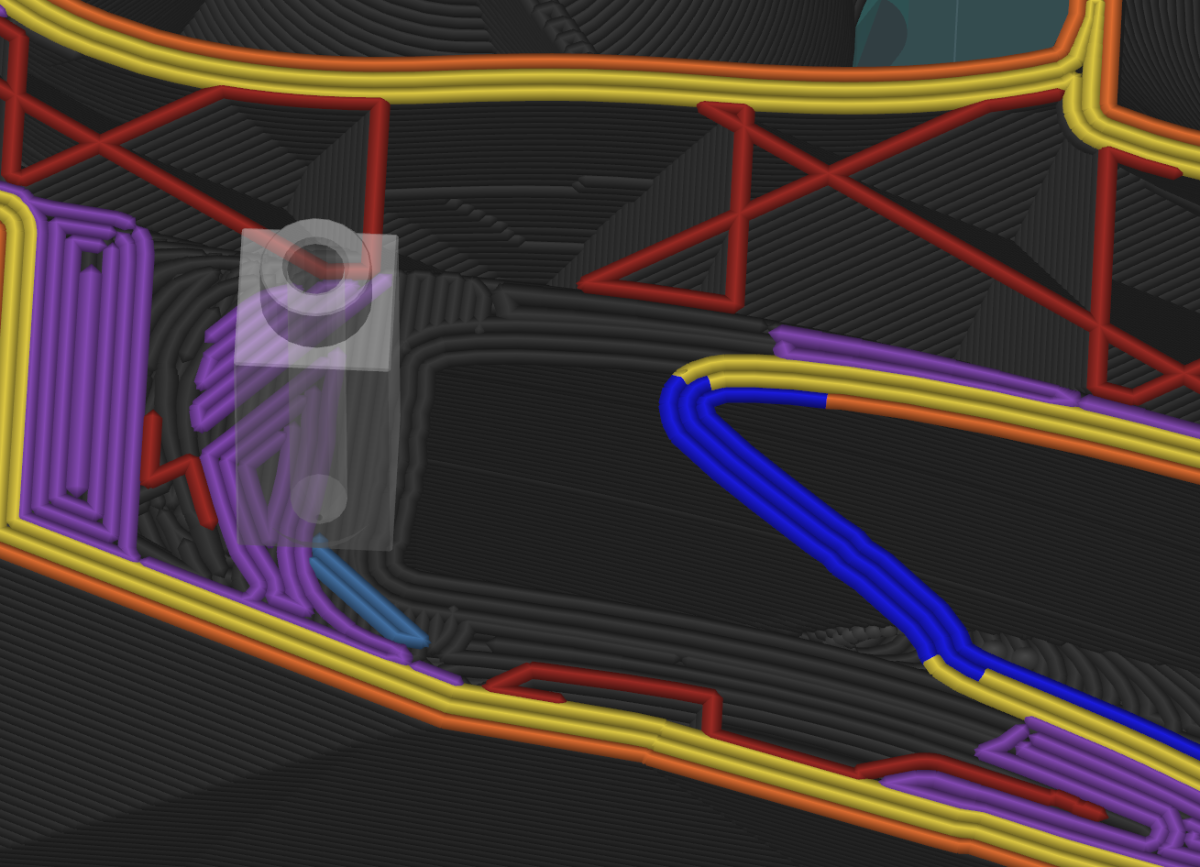
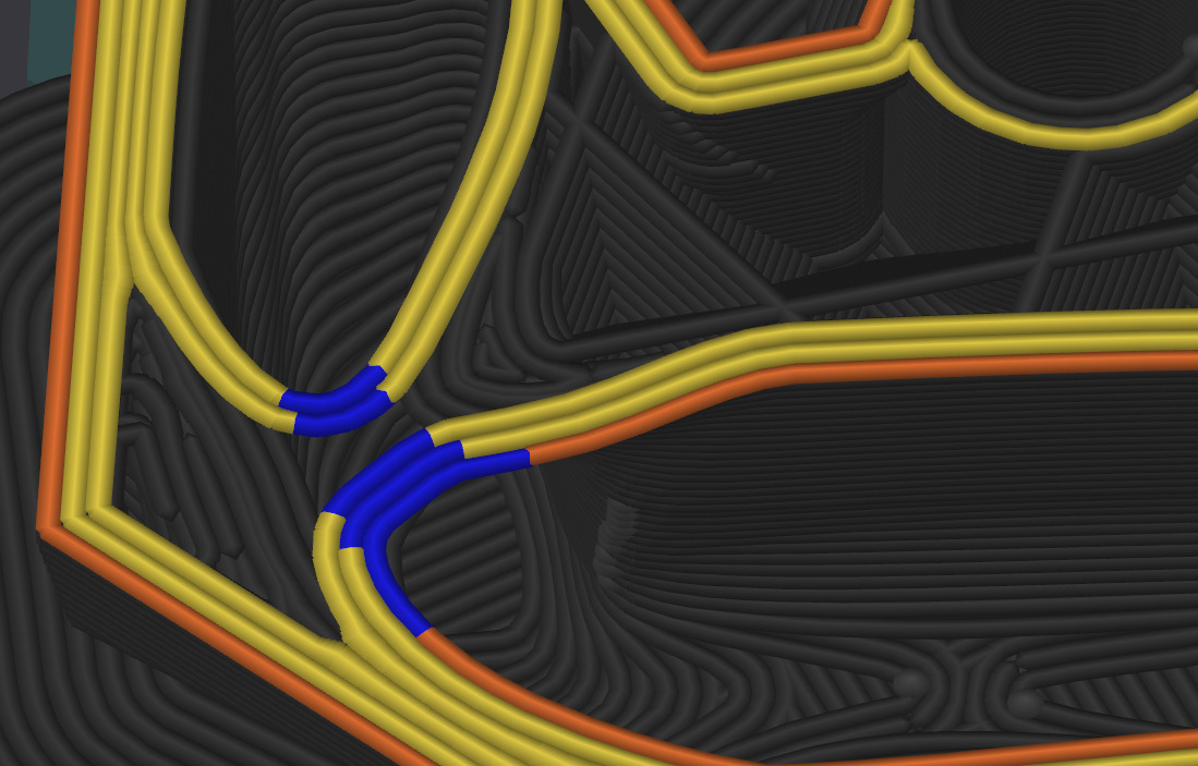
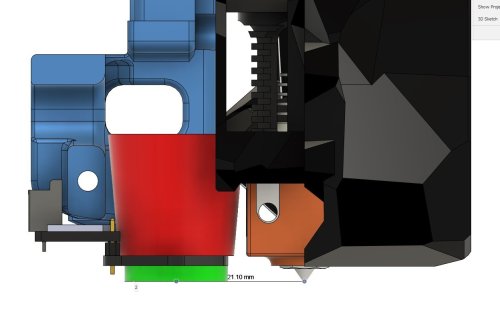
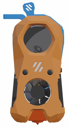
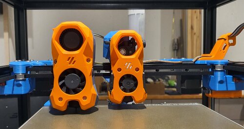
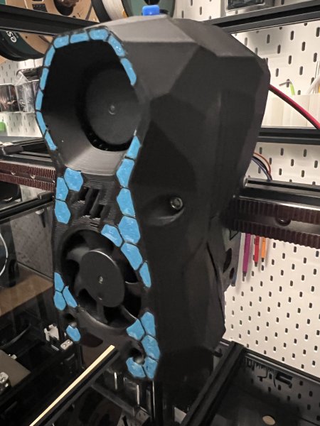
Hello, I need to print the air duct of the StealthBurner for a hotend change, but from the print preview, I was observing that there are several internal criticalities where there are unsupported protrusions that will most likely drip inside, creating several filaments that will increase the resistance to airflow. Could you advise me on the best printing settings or share a tested 3mf project? I've noticed that printing the infill first would help a lot since it would print the bridges first and then the walls, in addition to the order of the I/O walls. Here are some images:
-
Version 1.2.5
23,612 downloads
The Mini Stealth v2 toolhead is up on GitHub now. I will keep these files here as the new parts are not compatible with the v1.2.5 parts. I will support both versions in the comments here. I still need to create new assembly instructions but a lot of the steps are similar to what is described here. --------------------------------------------------------------------------- This toolhead scales down the body of the Stealthburner to a size which fits into a V0.1/2. Fully assembled it weighs less than 260 grams. It is designed around the Mini Sherpa extruder and has versions for the Phaetus Dragonfly, Dragon and Rapido HF hotends as well as versions for the Mosquito, the Revo Voron and the Creality Spider Pro hotends. It incorporates a status LED as well as two for print visibility. I have also added stretched versions that should fit the Rapido UHF, Dragon UHF and the VolcoMosq hotends. The Dragon UHF and Rapido UHF hotends can fit in the same shroud. The UHF hotends will reduce Z travel by 8.5mm and the VolcoMosq by 3mm. I cannot verify the fitment so if there are any issues please leave a comment. There are now two hex pattern inlays based on the design by 3DP-MAMSIH and a tutorial on how to apply them to the shroud. The negative body feature of Prusa/Super Slicer can also be used to create a crop-top version of the shroud as described at the end of the tutorial. The shroud uses a pair of 4010 blowers which produce more airflow than a 5015 blower while also being notably less noisy and drawing less current. The depth of these fans do limit Y travel by 3mm on a V0.1 while the door is closed and tophat is on. The width of the main body at its base is also a very tight fit at the extremes of X travel. The shroud fits a 3010 hotend fan or a 3007 fan by using a clip-in adapter. This Mini Stealth - Mini Sherpa also fits well in a V2.4 or Trident and modified x-frame left and right pieces are included. There are cable chain mounts as well as strain_relief and umbilical_PCB mount for use in the V0.1. There are additional x-frame pieces that allow this Mini Stealth to be installed on a Switchwire. The nozzle is moved up by 3mm compared to the official Switchwire. The x-frame has geometry that allows a BL-Touch to fit locked between the two pieces. I have included a magnet mount and additional shroud .stl files to make this compatible with the ZeroClick mod. This toolhead also has versions that allow mounting a differential IR sensor. I have removed the mechanical Z endstop on my V0.1 and use the IR probe as an endstop and it has greatly simplified my homing sequence. There are additional x-frame pieces that allow mounting the Beacon3D probe, Euclid or Biqu MicroProbe for a V2.4, Trident or Switchwire. The included Blender file shows the entire assembly complete with screws and should answer most basic questions. Note on MGN-9 installation: The default 2mm x 10 plastic threading screw is too long for mounting the x-axis endstop. An M2 x 8 does the job fine. For mounting to the linear carriage use four M3 x 6 flat-head screws. Note: The MGN carriage shown is an MGN-9H, not the shorter MGN-9C used in the V0.1 mod. Preparation I recommend using a file to lightly remove any printing artifacts on the mating face of the shroud. Use a small file to smooth out the break-off edges of the LED PCB and make sure the LED pockets are clear of 'droopy bits' All three fans will need the wire retention piece clipped so the wires fit into the shroud channels easier. Differential IR Probe Installation The IR Probe needs to be screwed into place with two M2.5x8 FHCS before installing any of the fans, except with the VolcoMosq or UHF hotends where the probe needs to be glued on with CA glue. The Y-offset for this probe is 4mm in front of the nozzle and the X-offset is 32mm. I strongly recommend removing the 3-pin header and soldering wires directly to the probe PCB. When installed the wires will route out from the back of the IR probe cover to then join with the hotend and fan wires. I have included a cover to allow a connector at the probe but the wire management will be less than ideal.. Assembly Instructions After pressing the status LED diffuser into place, install the right part-cooling fan first by feeding the wires through the small hole at the bottom. Then feed the wires for the status LED and hotend fan through before starting to push the LED carrier into position. Carefully push the status LED carrier as far as it will go and press the fan into position while making sure not to pinch the part-cooling fan wires. Then press the remaining LEDs into their slots. (I measure out 35mm of wire to connect these LEDs together) Here is another view also showing how the hotend fan wires fit through the hole on the side of the status LED carrier. Insert the second part-cooling fan and splice the wires together with the first fan. Install the hotend with at least two M2.5x6 screws (M3x6 for the Revo Voron). The heater cartridge should be installed away from the LEDs to avoid overheating them. ( ** don't forget the PTFE tube ) Pre-assemble the extruder with your chosen cable management using M3x20 BHCS before installing into the shroud. Install the extruder with two M3x8 BHCS. Make sure that the LED and fan wires route around and exit behind the extruder. They can even fit in the gap below the extruder as shown in the picture. Gather the wires together with zip ties and secure them up to the cable management piece. Do your best to keep them tucked in close at the base of the extruder. I used a temporary zip tie at the top to keep the wires manageable until I installed the toolhead in the printer. The top of the cable door hooks under the back of the shroud and then you can use 2 - M3x6 BHCS to secure the cable door in place. Use two M3x40 BHCS to secure the toolhead to the x-carriage in a V0.1/V0.2. For installation in a Trident or V2.4 use two M3x50 BHCS. Happy Printing!- 75 comments
- 1 review
-
- 23
-
-
-
-
- mini sherpa
- stealthburner
- (and 16 more)
-
Version 0.8
203 downloads
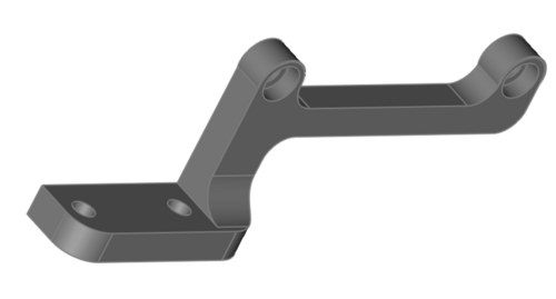
This is a flexure based nozzle probing option for mounting the Mini Stealth toolhead in a Voron Trident or V2.4. It uses a simple linear compliant mechanism to provide ~0.5mm of Z travel while being quite rigid in the other axes. It weighs around 20g fully assembled with Z and X endstops. It should require the same Print_Start preparations as the Voron TAP to ensure a clean nozzle and accurate probing. While probing with a scale on top of the bed, it applys about 600g of force. There are a few supports (shown in green) built in to make printing more reliable. After printing, the two inner sections will need to be gently, but firmly, pried apart from the two bridge sections while being careful not to plastically deform the flexures. There are four pockets for M3 square nuts to secure the Mini Stealth core piece using two M3x45 BHCS at the top and two M3x12 BHCS on the bottom. There are several different rear boss pieces depending on where you have your X endstop mounted. This piece is secured with a pair of M2x10 self tapping screws. Assembly: After ensuring that the flexure moves freely, install one of the grub screws in the top and screw it in just enough to remove the looseness in the flexure. This provides a known lower limit of travel. Install the Z_Stop_Boss with two M2 x 10 screws from the front. Install the Z micro-switch with the red trigger on the left (viewed from the back). The wires can be fed to the front through the lower gap in the flexure. Install the other M3 grub screw on the bottom of the DAB_Z_Boss. Screw it in until you hear the micro-switch trigger and then turn it back out until the trigger releases. This makes the trigger travel distance less than 0.5mm. Mount the x-carriage to the MGN12C carriage with four M3x12 BHCS. There is room to pull the four belt ends through and trim them at the front face of the DAB. Stealthburner Version: This version of DAB is a drop-in replacement for the Stealthburner x-frame pieces. It uses slightly different hardware than the official Stealthburner assembly, as shown in the picture below. Stealthburner on a Switchwire: This version of DAB fits a Stealthburner onto a Switchwire. It is printed in two parts and assembled with three M2x10 self tapping screws. Please leave comments, questions and feedback.- 18 comments
-
- 8
-
-
- voron
- stealthburner
- (and 4 more)
-
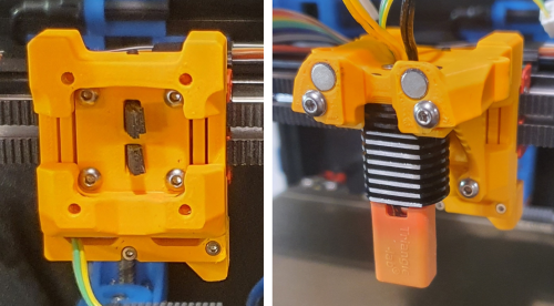
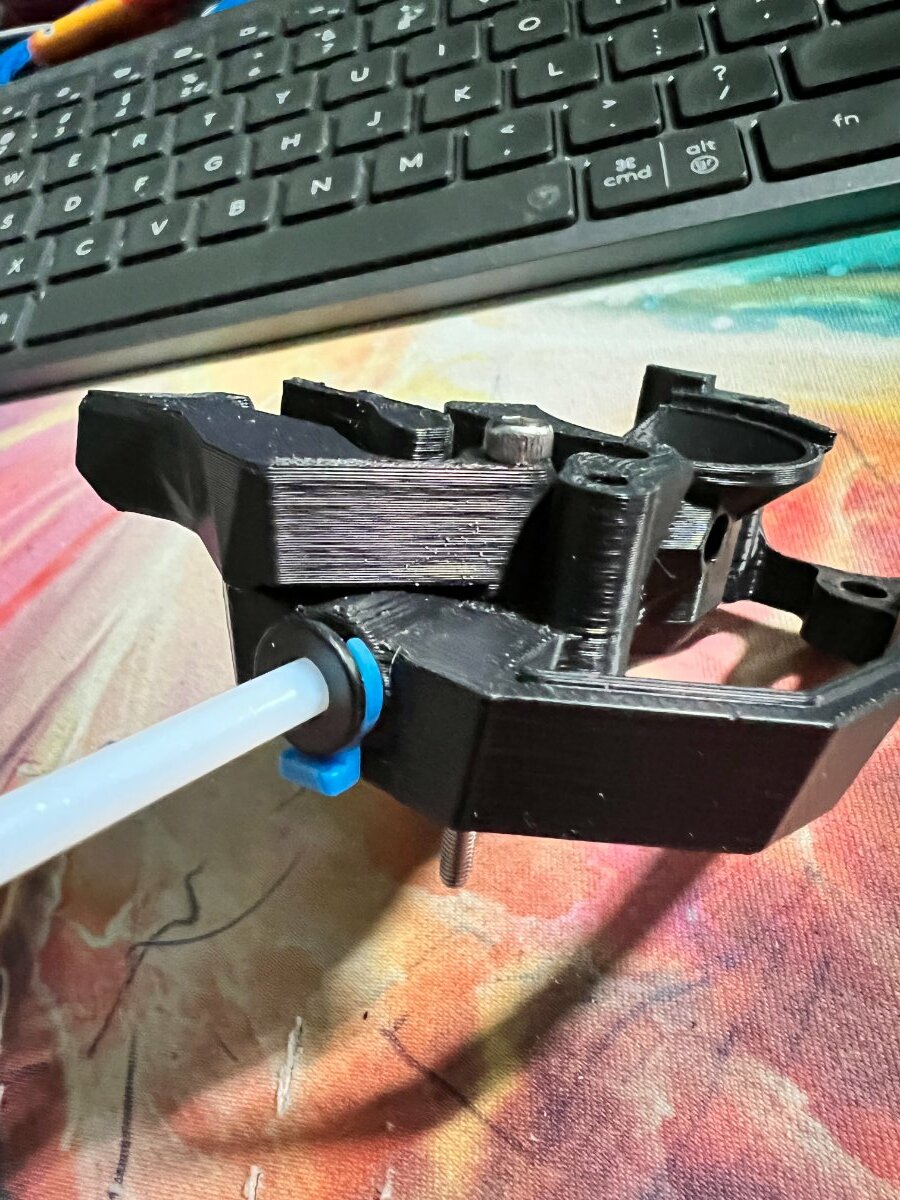
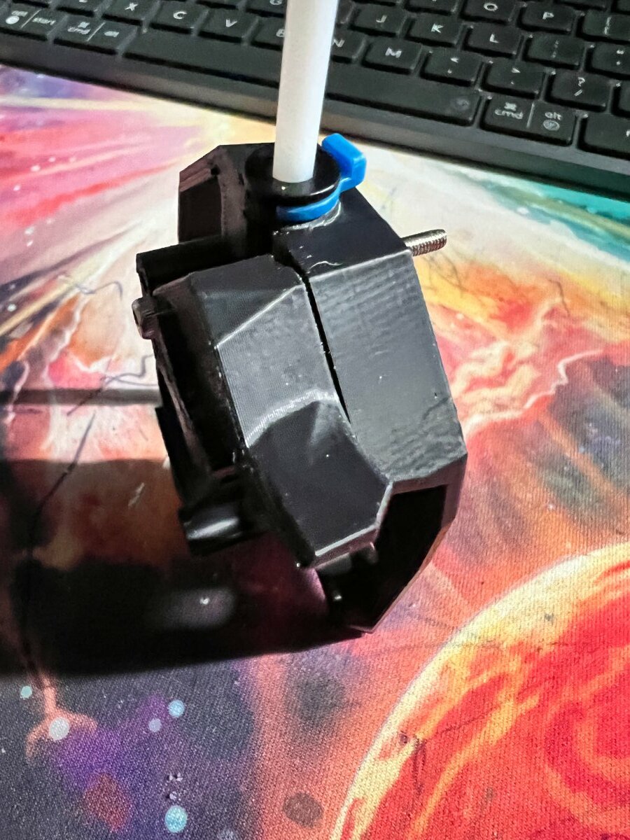
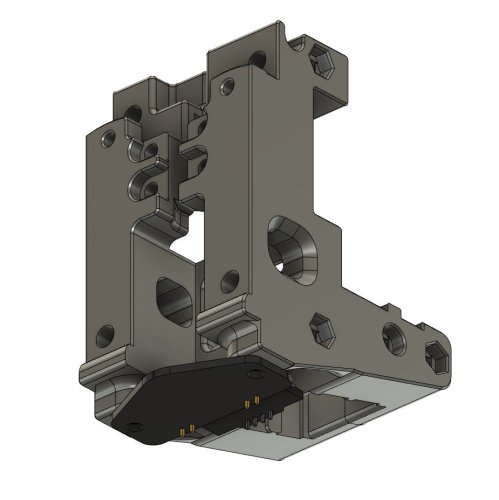
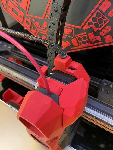
 Inspired by the LGX lite Mount for the Stealthburner, I really liked the possibility to use a UM2 clip to lock your bowden tube. https://github.com/Eytecz/LGX_Lite_Stealthburner_CW2_style_mount (images and STEP files there) I like the Stealthburner, but I really dont like inserting filament, pushing a bit too hard and pushing out the bowden tube... So, I thought, can I make this work on the original CW2 for Stealthburner? You need to know that I dont do 3d designing, my skills are from a 3 year old, but it doesn't mean its a bad idea... (I hope) So I started cutting, adding, printing, testing... fitting.. and came to this... first Alpha, then Apha2 or maybe Beta.. whatever.. Because the tube entry is now wider, it sticks out a bit, so had to shave of a bit from the Guidler, yet, doesnt have any negative effect and you almost cant see it. On the side its still full width, so you cant see any change looking at the Stealthburner form the front. Yet... big benefit of using the UM2 clip, I hope someone with Fusion skills or whatever picks this up and makes a good design, yet all tested and works from this STL's. [a]_guidler_b.UM2-Beta.stl main_body.UM2-Beta.stl
- 2 replies
-
- 1
-
-
- stealthburner
- cw2
- (and 2 more)
-
Version 1.0.0
937 downloads
I've made a mount for the Beacon3D probe for a CW2 Switchwire I used the normal version beacon probe Mount has been tested and works great, here is a youtube short of it in action *** I've added a second mount as that moved the probe 2mm further away I wasn't happy with the original mount because as soon as the carriage got a bit melted the probe would start touching the heat block. I also believe because the probe is so close to the heater it causes the mount the deform.- 15 comments
-
- 6
-
-
- switchwire
- clockwork2
- (and 3 more)
-

Version 1.0.0
2,953 downloads
I've made some alternative beacon mounts for myself that i'll share I wasn't happy with the original mount because as soon as the carriage got a bit melted the probe would start touching the heat block (see attached photo). I also believe because the probe is so close to the heater it causes the mount the deform. I've made a mount that sits the probe back 2mm from the original but I have not tested this one, this brings me the other other mount I made. The second mount is specific to a Dragon hotend that is rotated 180°. I did this to be able to see the nozzle better and it's now possible as there is no more probe in the way of achieving this. So far it's working well for me I've printed my parts out of PCCF so if anyone can report their findings with an ABS mount that would be great but moving the probe should have done the trick. The original beacon mount from annex can be found here if you were looking for that: https://github.com/Annex-Engineering/Annex-Engineering_User_Mods/tree/main/Printers/Non_Annex_Printers/VORON_Printers/VORON_V2dot4/annex_dev-stealthburner_beacon_x_carriage- 5 comments
- 1 review
-
- 8
-
-
-
- voron
- clockwork2
- (and 3 more)
-
Version 1.2.5
22,551 downloads
The Mini Stealth v2 toolhead is up on GitHub now. I will keep these files here as the new parts are not compatible with the v1.2.5 parts. I will support both versions in the comments here. I still need to create new assembly instructions but a lot of the steps are similar to what is described here. --------------------------------------------------------------------------- This toolhead scales down the body of the Stealthburner to a size which fits into a V0.1/V0.2. Fully assembled it weighs about 120 grams less than the original. It is designed around the Bondtech LGX Lite extruder and has versions for the Phaetus Dragonfly, Dragon and Rapido HF hotends as well as versions for the Mosquito, the Revo Voron and the Creality Spider Pro hotends. It incorporates a status LED as well as two for print visibility. I have added new stretched versions that should fit the Rapido UHF, Dragon UHF and the VolcoMosq hotends. The Dragon UHF and Rapido UHF hotends can fit in the same shroud. The UHF hotends will reduce Z travel by 8.5mm and the VolcoMosq by 3mm. I cannot verify the fitment so if there are any issues please leave a comment. There are now two hex pattern inlays based on the design by 3DP-MAMSIH and a tutorial on how to apply them to the shroud. The negative body feature of Prusa/Super Slicer can also be used to create a crop-top version of the shroud as described at the end of the tutorial. The shroud uses a pair of 4010 blowers which produce more airflow than a 5015 blower while also being notably less noisy and drawing less current. The depth of these fans do limit Y travel by 3mm on a V0.1 while the door is closed and tophat is on. The width of the main body at its base is also a very tight fit at the extremes of X travel. The shroud fits a 3010 hotend fan or a 3007 fan by using a clip-in adapter. The Mini Stealth LGX Lite fits well in a V2.4 or Trident and modified x-frame left and right pieces are included. There is a separate 'strain_relief' stl for use in the V0.1. There are also x-frame pieces that allow this Mini Stealth to be installed on a Switchwire. The nozzle is moved up by 3mm compared to the official Switchwire. The x-frame has geometry that allows a BL-Touch to fit locked between the two pieces. I have included a magnet mount and additional shroud .stl files to make this compatible with the ZeroClick mod. This toolhead also has versions that allow mounting a differential IR sensor. I have removed the mechanical Z endstop on my V0.1 and use the IR probe as an endstop and it has greatly simplified my homing sequence. There are additional x-frame pieces that allow mounting the Beacon3D probe, Euclid or Biqu MicroProbe for a V2.4, Trident or Switchwire. The included Blender file shows the entire assembly complete with screws and should answer most basic questions. Note on MGN-9 installation: The default 2mm x 10 plastic threading screw is too long for mounting the x-axis endstop. An M2 x 8 does the job fine. For mounting to the linear carriage use four M3 x 6 flat-head screws. Note: The MGN carriage shown is an MGN-9H, not the shorter MGN-9C used in the V0.1 mod. Preparation I recommend test fitting the extruder, LGX_lite_adapter_plate, PTFE tube and hotend into the shroud before running any wires to ensure that the PTFE tube length is correct and everything fits. It helps to chamfer the edge of the tube with a sharp blade so that it doesn't snag in the hotend. I is a good idea to use a file to lightly remove any printing artifacts on the mating face of the shroud. All three fans will need the wire retention piece clipped so the wires fit into the shroud channels easier. Use a small file to smooth out the break-off edges of the LED PCB and make sure the LED pockets are clear of 'droopy bits' Differential IR Probe Installation The IR Probe needs to be screwed into place with two M2.5x8 FHCS before installing any of the fans, except with the VolcoMosq or UHF hotends where the probe needs to be glued on with CA glue. The Y-offset for this probe is 4mm in front of the nozzle and the X-offset is 32mm. I strongly recommend removing the 3-pin header and soldering wires directly to the probe PCB. When installed the wires will route out from the back of the IR probe cover to then join with the hotend and fan wires. I have included a cover to allow a connector at the probe but the wire management will be less than ideal.. Assembly Instructions After pressing the status LED diffuser into place, install the right part-cooling fan first by feeding the wires through the small hole at the bottom. Then feed the wires for the status LED and hotend fan through before starting to push the LED carrier into position. Carefully push the status LED carrier as far as it will go and press the fan into position while making sure not to pinch the part-cooling fan wires. Then press the remaining LEDs into their slots. (I measure out 35mm of wire to connect these LEDs together) Here is another view also showing how the hotend fan wires fit through the hole on the side of the status LED carrier. Insert the second part-cooling fan and splice the wires together with the first fan. Install the hotend with at least two M2.5x6 screws (M3x6 for the Revo Voron). The heater cartridge should be installed away from the LEDs to avoid overheating them. ( ** don't forget the PTFE tube ) Pre-assemble the extruder pieces before installing into the shroud. Use M3x30 screws to attach motor_bridge. Install the extruder with an M3x6 BHCS on the back and then an M3x12 from below. Ensure the cables are routed as flat to the shroud as possible and secure them with zip ties. Install the strain_relief or cable_chain_mount with two M3x8 screws and the cable_door with another M3x8 screw. Close the cable door with an M3x6 screw. Use two M3x40 BHCS to secure the toolhead to the x-carriage in a V0.1/V0.2. For installation in a Trident or V2.4 use two M3x50 BHCS. Happy Printing!- 180 comments
-
- 23
-
-
-
- lgx lite
- stealthburner
- (and 19 more)
-
Version 1.2.5
13,850 downloads
The Mini Stealth v2 toolhead is up on GitHub now. I will keep these files here as the new parts are not compatible with the v1.2.5 parts. I will support both versions in the comments here. I still need to create new assembly instructions but a lot of the steps are similar to what is described here. --------------------------------------------------------------------------- This toolhead scales down the body of the Stealthburner to a size which fits into a V0.1/V0.2. Fully assembled it weighs about 80 grams less than the original. It is designed around the Orbiter 1.5 extruder and has versions for the Phaetus Dragonfly, Dragon and Rapido HF hotends as well as versions for the Mosquito and the Revo Voron hotends. It incorporates a status LED as well as two for print visibility. There are now two hex pattern inlays based on the design by 3DP-MAMSIH and a tutorial on how to apply them to the shroud. The negative body feature of Prusa/Super Slicer can also be used to create a crop-top version of the shroud as described at the end of the tutorial. I have added new stretched versions that should fit the Rapido UHF, Dragon UHF and the VolcoMosq hotends. The Dragon UHF and Rapido UHF hotends can fit in the same shroud. The UHF hotends will reduce Z travel by 8.5mm and the VolcoMosq by 3mm. I cannot verify the fitment so if there are any issues please leave a comment. It uses a pair of 4010 blowers which I found to produce more airflow than a 5015 blower while being notably less noisy and drawing less current. The depth of these fans do limit Y travel by 3mm on a V0.1 while the door is closed and tophat is on. The width of the main body at its base is also a very tight fit at the extremes of X travel. I have raised my tophat by 20mm which gives the cabling and filament tube plenty of room to breathe. The shroud fits a 3010 hotend fan or a 3007 fan by using a clip-in adapter. I have also installed this on my Trident. The included files do not address cable management on a Trident or V2.4 but do provide mounting to the MGN12 carriage. The cable chain on a Trident or V2.4 would have to be moved back at least 5mm to clear the extruder stepper motor. There is a separate 'strain_relief' stl for use in the V0.1. There are also x-frame pieces that allow this Mini Stealth to be installed on a Switchwire. The nozzle is moved up by 3mm compared to the official Switchwire due to the stepper motor being so low on the Orbiter extruder but this also allows a BL-Touch to fit into the x-frame pieces. I have included a magnet mount and additional shroud .stl files to make this compatible with the ZeroClick mod. This toolhead also has versions that allow mounting a differential IR sensor. I have removed the mechanical Z endstop on my V0.1 and use the IR probe as an endstop and it has greatly simplified my homing sequence. There are additional x-frame pieces that allow mounting the Beacon3D probe, Euclid or Biqu MicroProbe for a V2.4, Trident or Switchwire. The included Blender file shows the entire assembly complete with screws and should answer most basic questions. Note on MGN-9 installation: The default 2mm x 10 plastic threading screw is too long for mounting the x-axis endstop. An M2 x 8 does the job fine. For mounting to the linear carriage use four M3 x 6 flat-head screws. Note: The MGN carriage shown is an MGN-9H, not the shorter MGN-9C used in the V0.1 mod. Preparation I recommend using a file to lightly remove any printing artifacts on the mating face of the shroud. Use a small file to smooth out the break-off edges of the LED PCB and make sure the LED pockets are clear of 'droopy bits' All three fans will need the wire retention piece clipped so the wires fit into the shroud channels easier. Differential IR Probe Installation The IR Probe needs to be screwed into place with two M2.5x8 FHCS before installing any of the fans, except with the VolcoMosq or UHF hotends where the probe needs to be glued on with CA glue. The Y-offset for this probe is 4mm in front of the nozzle and the X-offset is 32mm. I strongly recommend removing the 3-pin header and soldering wires directly to the probe PCB. When installed the wires will route out from the back of the IR probe cover to then join with the hotend and fan wires. I have included a cover to allow a connector at the probe but the wire management will be less than ideal.. Assembly Instructions After pressing the status LED diffuser into place, install the right part-cooling fan first by feeding the wires through the small hole at the bottom. Then feed the wires for the status LED and hotend fan through before starting to push the LED carrier into position. Carefully push the status LED carrier as far as it will go and press the fan into position while making sure not to pinch the part-cooling fan wires. Then press the remaining LEDs into their slots. (I measure out 35mm of wire to connect these LEDs together) Here is another view also showing where the hotend fan wires fit. Insert the second part-cooling fan and splice the wires together with the first fan. Install the hotend with at least two M2.5x6 screws (M3x6 for the Revo Voron). The heater cartridge should be installed away from the LEDs to avoid overheating them. ( ** don't forget the PTFE tube ) Gather the wires together and secure them with the first zip-tie. (it helps to insert a snipped zip-tie through the the hole and yank it through with pliers to remove printing artifacts from inside of the channels) Loop the wire bundle back around and add in the LED and hotend fan wires. Use two more zip-ties to secure everything in place. ENSURE to leave room for the extruder by lifting the loop of wires up and out of the way as shown. More space is much better than not enough. (Don't forget the PTFE tube) Pre-assemble the extruder pieces before installing into the shroud. Use two M3x8 BHCS to install the Orbiter 1.5 extruder. It helps to have both screws in the Orbiter before putting it in place. Start the screw by the latch and then the blind screw should be easier to align. Gather all of the wires together and then use a zip-tie to secure them to the motor-bridge. Leave a little slack in the extruder wires. Install the strain_relief with two M3x6/8 screws and the cable_door with a M3x10/12 screw. Close the cable door with a M3x6 screw and screw in the extruder tensioning thumb screw. Use two M3x40 BHCS to secure the toolhead to the x-carriage in a V0.1/V0.2. For installation in a Trident or V2.4 use two M3x50 BHCS. Happy Printing!- 43 comments
-
- 13
-
-
-
-
 I know I'm a pretty new builder but I've never been quite satisfied with clockwork2, and I am looking for a better solution. I see the LGX lite come up a lot for this and it seems like a pretty solid system. Is there any mounting bracket for stealthburner that will let it use the 2 part hartk PCB? Is there a better extruder option than the LGX lite (and preferably also takes the 2 part hartk PCB)?
 -
Version 1.1.0
570 downloads
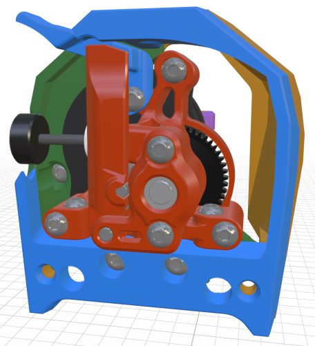
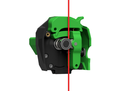
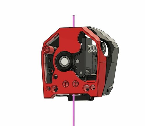
This remix of the Sherpa Micro extruder uses the RIDGA gears from a Vz Hextrudort. Other than using 'twirl' gears, they are also 5mm shorter than the standard Bondtech gears which solves the collision that a stock Sherpa has with the 5015 blower in a Stealthburner. I mirrored the extruder about the Y axis to put the tensioning screw on the left side and added a filament release lever since the idler_arm is not accessible when installed in a Steathburner. This requires a modified idler_arm for ridgidity. I have also added a shield over the 50t gear to protect the toolhead wiring. This design fits the official Stealthburner_main_body as well as the official cable_door. The cable chain mounts were adjusted to clear the stepper motor but otherwise remain stock. Below is a list of the hardware that differs from a standard Stealthburner CW2 install. 1 - Mellow CNC Vz HextrudORT drive gears Set 7 2 - M3x25 screws below extruder (from the front) 1 - M2x10 self tapping screw at the top (from behind) 2 - M3x12 screws to secure extruder 1 - M3x10 screw to attach filament release lever The Sherpa Micro Vz RIDGA will need some basic components from a BMG Dual Drive kit. 2 - MR85 bearings 1 - Thumbscrew with tensioning spring and washer 2 - 3mm steel pins for idler_arm pivot and idler gear The included .blend file shows the complete CW2 assembly with hardware. You can select any part and press [H] to hide it. Pressing [Alt] + [H] shows everything again. Pressing [F2] while a part is selected brings up the Rename dialog so you can see the name of each component i.e. "M3x25_BHCS". I have included .stl files for building a standard Sherpa Micro, with standard BMG gears, but adding the filament_release_lever. The files added here are mirrored to put the tension screw on the left but can each be mirrored back in the slicer to match the official orientation. Below is a list of the parts required: 1 - Sherpa_Micro_VzRIDGA_Back_v1.1.stl 1 - Sherpa_Micro_Core_mirrored.stl (official geometry mirrored) 1 - Sherpa_Micro_VzRIDGA_Front.stl (official geometry mirrored) 1 - Sherpa_Micro_Idler_Arm_FR-Lever_mirrored.stl 1 - Sherpa_Micro_VzRIDGA_Filament_Release_Lever.stl The extruder parts are licensed under the Annex Engineering License and the Clockwork 2 parts are licensed under the GPL v3 License.- 3 comments
-
- 3
-
-
-
- stealthburner
- clockwork2
- (and 1 more)
-
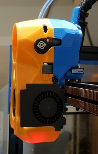
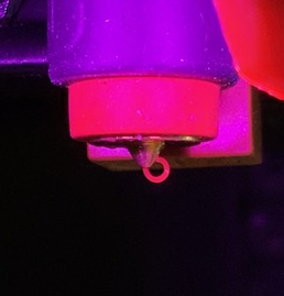
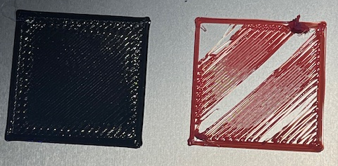
Team, I recently finished my V 2.4 with Stealthburner and immediately began printing getting pretty good results. As I was going through the process of tuning (Voron/Ellis), the first layers went to crap bad enough that I can no longer print. I have taken the toolhead completely apart twice and found no obvious issues. It still looks new. Following extensive inspection and testing I have concluded that there is a problem with the nozzle. As it begins to extrude, the PLA curls back on the nozzle eventually creating a ball of plastic. It looks like that ball of plastic contacts and rips up the first layer (see second photo). You can also see on the second red patch that it appears that the flow of plastic is insufficient in that it is necking down? I know very little about printing plastic and would appreciate some help. As part of the tuning process I have played with the Z offset. It hardly makes a difference as I adjust the value. The extruded plastic should exit straight down? Is the nozzle partially clogged causing the curling? If yes, how do you suggest I clear it? 0.4 mm drill? Thanks all for your input. In the meantime I am going back to square one and repeating the initial startup procedures. Edit: Bob
-
I have a v2.4 with a stealthburner, and I think the biggest problem the printer has is the cooling, which seriously limits my print speed. I've been interested in improving the cooling, and wondered if anyone had any suggestions. My stealthburner uses a regular LGX, mosquito magnum hotend, and the Voron TAP, in case those affect anything.
-

Version 1.0.0
205 downloads
CatPaw is the ideal toolhead for Voron Zero series with Orbiter 2.0 Extruder. I developed this toolhead as I was unhappy with the existing options. The standard Voron Zero 0.2 toolhead does not provide as much cooling as I prefer, and certainly less than the StealthBurner toolhead. My design goals were also minimum loss of print volume and maximum compatibility with toolheads and options for probe and filament sensor. CATPAW: Uses Voron Zero 0.2 toolhead cartridges, so should work with all toolheads for voron Zero 0.2 (fan saver recommended) 2x 4010 Blowers, with StealthBurner duct layout for near arctic level part cooling (2x 4010 provides more air than StealthBurner toolhead) Almost no loss in print volume. X axis should be full width, loss off a millimeter or so on X if you print with your door closed. (Magnets on my door are strong enough, so the door closes again if the toolhead bumps into it, giving me the full 120x120 mm even when printing ABS Option to add the slideswipe Probe. I shortened the probe, but all other parts can be used from https://github.com/SaltyPaws/Voron_0.1and0.2mods/SlideSwipe or original repo (https://github.com/chestwood96/SlideSwipe) Option to add under extruder filament Sensor Carriages are provided for MGN7 and MGN9 X-axis rails. It is recommended to print the provided X carriage for the appropriate rail. In order to minimize toolhead height, I lowered the screw hole for the rear mounting screw. The CATPAW toolhead will work with the stock Voron Zero 0.2 Carriage, but the screw securing the X-carriage from the rear will not fit. https://github.com/SaltyPaws/CATPAW_toolhead/raw/main/images/PXL_20240101_224037977.jpg?raw=true BOM 2x SHCS (preferred) or BHSC M3x25 bolt 3x M3 nut 2x NeoPixel 1x 3010 hotend fan 2x 4010 Blower 6x3mm magnets for probe (optional) 6mm steel ball for filament sensor (optional) Omron D2F-L micro-switch with lever for filament sensor (optional) 2x M2x12 or self-tapping screw to secure micro-switch (optional) Installation Instructions Assembly should be done in the following order: Probe Solder wires to 6x3mm magnets. In order to prevent loss of magnetism, let the magnets cool against another 6x3 magnet. Press the magnets into the slots by pushing the toolhead down on a hard object. Use a large flat soldering tip at around 230C to push the magnets deeper into the slots, you want the magnets to stick out ~0.5 to 1 mm. Again, let the magnets cool down attached to other magnets to prevent loss of magnetism. Ensure wire to magnet path has very low resistance (less than 4 ohm). route wires out trough little side window. Seal hole with red gasket maker. NeoPixels Create a chain of 2 neopixels. You do not have a lot of space to hide excess cable, so make the wires between the neopixels as short as possible, while still allowing them to slide into the slots. Test the neopixels! It will be more rework to remove the hotend fan and part cooling fans later. Fans First install 3010 part cooling fan. Be very careful to only press the edges of the fan, the fan will break when pushing the center of the fan (ask me how I know...) Then proceed with installing the blower fans. Use a knife to cut the upper right hand side of the blower fan (looking back to front). This is required for routing the majority of the wires. I used superglue to keep the fan together as you will remove a fan closing latch. I accidentally cut int the fanbox, and sealed up the hole with red gasket maker. For details - see pictures below: https://github.com/SaltyPaws/CATPAW_toolhead/raw/main/images/PXL_20231225_175242278.jpg?raw=true https://github.com/SaltyPaws/CATPAW_toolhead/raw/main/images/PXL_20231225_175256608.jpg?raw=true https://github.com/SaltyPaws/CATPAW_toolhead/raw/main/images/PXL_20231225_175325632.jpg?raw=true Toolhead Cardridge Ensure the heater wires are installed pointing towards the right hand fan that has space for wire routing. Thermistor, probe and fan wires will fit on the other side (left hand side fan). Hold off on installing the zip-ties, these are best installed after the toolhead is installed on the carriage. Filament Sensor Solder wires to filament sensor (2 outer most legs). You may want to shorten the legs somewhat for an easier fit. Trim lever, so that lever does not extend past micro-switch body Install micro-switch and ball Test sensor Install Toolhead Carefully mount toolhead, ensuring that wires are not pinched, and belt is not rubbing on gantry. The bulk of the wires will go in the gap carved out on the right hand side fan, the other side will have sufficient space for probe and fan wires. Min Probe See installation instructions in orignal repo: https://github.com/chestwood96/SlideSwipe-
- 2
-
-
- orbiter 2.0
- orbiter
- (and 33 more)
-
Version 1.0.0
36 downloads
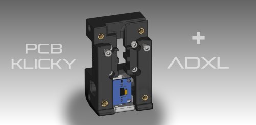
Probe Mount with ADXL for PCB Klicky Use the free space above the PCB Klicky Probe for an ADXL! This mount is a new variant of: https://github.com/tanaes/whopping_Voron_mods/tree/main/pcb_klicky ADXL345: https://amzn.eu/d/dJvU8Zh ADXL345 is attached with 2 M2.5 screws. I didn't solder the JST-XH 3 pin header to the PCB Klicky board, but soldered the cables directly to the board. There is not enough space for the header. happy printing! -
Version 1.0.1
2,502 downloads
https://github.com/JaredC01/Galileo BOM Galileo componants 4x M3X25 3x M3X16mm 8x heat brass insert (BOM insert) Appreciate my work ? buy me a coffee https://www.paypal.com/donate/?hosted_button_id=9EL8CEDVY28DA thank you and happy printing- 21 comments
-
- 12
-
-
-
-
Version 1.0.0
4,623 downloads
Orbiter 1.5 on SB 20/04/2022 .step available my config rotation_distance: 35.1 gear_ratio: 75:10 microsteps: 32 full_steps_per_rotation: 200 #200 for 1.8 degree, 400 for 0.9 degree nozzle_diameter: 0.400 filament_diameter: 1.75 max_extrude_only_velocity: 60 thanks to Eytecz (https://github.com/Eytecz/LGX_Lite_Stealthburner_CW2_style_mount/ ) for his mount of lgx lite on SB to inspire me to complet this orbiter 1.5 . i hope you like it- 43 comments
-
- 19
-
-
-
- orbiter
- stealthburner
- (and 1 more)
-
Version 1.0.0
147 downloads
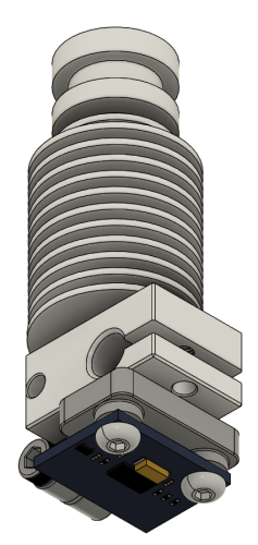
I was shocked to see a significant difference between the results measured with the built-in accelerometer on the EBB36 board and those obtained using this nozzle mount. Here are the results: the sensor built into the EBB36 board X-axis shaper type: mzv, frequency: 62.4 Y-axis shaper type: mzv, frequency: 43.6 with this nozzle mount X-axis shaper type: 2hump_ei, frequency: 99.4 Y-axis shaper type: 2hump_ei, frequency: 87.8 What are your thoughts on this? Are these measured values really necessary for my printer? Required Qty 1 - M3 insert nuts Qty 1 - M3 x 10 socket head screw Qty 2 - M3 x 6 socket/button head screw- 1 comment
-
- 3
-
-
- voron
- stealthburner
- (and 2 more)
-
Version 1.0.2
290 downloads
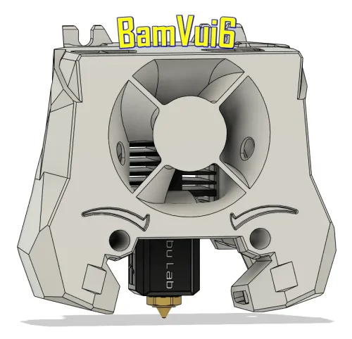
This mod allows you to mount the Bambulab clone hotend with a V6 nozzle onto the Stealth Burner. -
Version 1.0.0
462 downloads
ebb42 mount for cw1 nema17 pancake with umbilical strain relief Decided to go to canbus umbilical for my stealthburner on cw1 and remove both x and y cable chains. As the ebb42 is a new product there had been no mounts that have been released at that time so i came up with this design. The mount sits comfortably on the rear of my extruder nema17 pancake motor and spaces the ebb42 nicely away from the rear of the motor, the m3 motor screws i have are slightly to long so i used spacers on top of the ebb42 to counteract this, also i used a cable strain relief to protect the 4 wires to the ebb42 which the dimentions are 5mm hole, 28mm length, diameter 11.8mm, slot diameter 7.55mm x2.1mm which goes into a little slide in wedge to hold into place and also used expandable braided sleeving size 3-9mm which protects the wires and sits nice and snug in the strain relief. i also modified the original stealthburner cw1 pcb cover by Demosth to fit with this mount (https://www.teamfdm.com/files/file/535-stealthburner-cw1-pcb-cover).- 10 comments
-
- 6
-
-
- stealthburner
- ebb42
- (and 3 more)
-
does anyone know stealthburner gear ratio. i know stock is 50:17 using bmg gears but this has a 10 tooth gear for the drive.
-
From the album: Voron 2.4 R2 Build by Buurman
-
Version 1.0.0
121 downloads
This version of bltouch mount for stealthburner was designed to avoid covering the fan area. Also has spacer tubes for the screws that mount it. v. 1.0.0 Nothing fancy. I use raft on tube spacers but nothing on other files. -
hey guys i am trying to install a lgx lite on a stealthburner and i cant seem to find a good source of video to help me out. can someone point me in the right direction?
-
Version 1.1.0
52 downloads
I wanted to use Tap instead of Klicky/euclid probe on my V2.4 but i only had CW1 with Stealthburner so i set about seeing if it was possible to modify CW1 to fit TAP as CW1 motor mount fixes from the rear which TAP can't do. I managed to find a solution so now this CW1 mod fixes from the front instead of the rear. The left side mounting screw now fixes the CW1 Extruder Motor Plate from the front with an M3x8 SHCS screw going through to the heatset in the Tap Upper as in Pic1, the same as designed for CW2. The right side screw now goes through the font of the CW1 Extruder Body with an M3x30 SHCH screw going through to the heatset in the Tap Upper as in Pic2, again the same as designed for CW2 Once the two parts of CW1 are mounted to the TAP then the Printhead Rear/Front can be mounted on the Tap as per Tap instructions for CW2 printhead mounting, the CW1 Extruder Body has access cut outs in the front for alen keys to be able to tighten those little screws that hold the printhead in place, the rest of the build is as per TAP SB fitting instructions. I have had this mod on my V2.4 with SB and CW1 for a couple of months now and it works great....-
- 6
-
-
-
- tap
- stealthburner
- (and 3 more)