Search the Community
Showing results for tags 'umbilical'.
Found 4 results
-

Version 1.2.5
48,438 downloads
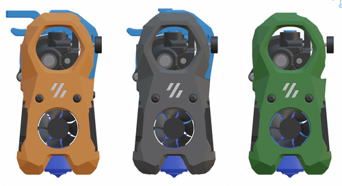
The Mini Stealth v2 toolhead is up on GitHub now. I will keep these files here as the new parts are not compatible with the v1.2.5 parts. I will support both versions in the comments here. I still need to create new assembly instructions but a lot of the steps are similar to what is described here. --------------------------------------------------------------------------- This toolhead scales down the body of the Stealthburner to a size which fits into a V0.1/V0.2. Fully assembled it weighs about 110 grams less than the original. It is designed around the Orbiter 2.0 extruder and has versions for the Phaetus Dragonfly, Dragon and Rapido HF hotends as well as versions for the Mosquito, the Revo Voron and the Creality Spider Pro hotends. It incorporates a status LED as well as two for print visibility. I have added new stretched versions that should fit the Rapido UHF, Dragon UHF and the VolcoMosq hotends. The Dragon UHF and Rapido UHF hotends can fit in the same shroud. The UHF hotends will reduce Z travel by 8.5mm and the VolcoMosq by 3mm. I cannot verify the fitment so if there are any issues please leave a comment. There are now two hex pattern inlays based on the design by 3DP-MAMSIH and a tutorial on how to apply them to the shroud. The negative body feature of Prusa/Super Slicer can also be used to create a crop-top version of the shroud as described at the end of the tutorial. The Mini Stealth uses a pair of 4010 blowers which produce more airflow than a 5015 blower while being notably less noisy and drawing less current. The depth of these fans do limit Y travel by 3mm on a V0.1 while the door is closed and tophat is on. The width of the main body at its base is also a very tight fit at the extremes of X travel. I have raised my tophat by 20mm which gives the cabling and filament tube plenty of room to breathe. The shroud fits a 3010 hotend fan or a 3007 fan by using a clip-in adapter. This Orbiter 2.0 Mini Stealth is a better fit than the Orbiter 1.5 Mini Stealth in a V2.4 or Trident as the motor no longer interferes with the path of the cable chain. There is a separate 'strain_relief' stl for use in the V0.1. There are also x-frame pieces that allow this Mini Stealth to be installed on a Switchwire. The nozzle is moved up by 3mm compared to the official Switchwire due to the stepper motor being so low on the Orbiter extruder but this also allows a BL-Touch to fit into the x-frame pieces. I have included a magnet mount and additional shroud .stl files to make this compatible with the ZeroClick mod. This toolhead also has versions that allow mounting a differential IR sensor. I have removed the mechanical Z endstop on my V0.1 and use the IR probe as an endstop and it has greatly simplified my homing sequence. There are additional x-frame pieces that allow mounting the Beacon3D probe, Euclid or Biqu MicroProbe for a V2.4, Trident or Switchwire. The included Blender file shows the entire assembly complete with screws and should answer most basic questions. Note on MGN-9 installation: The default 2mm x 10 plastic threading screw is too long for mounting the x-axis endstop. An M2 x 8 does the job fine. For mounting to the linear carriage use four M3 x 6 flat-head screws. Note: The MGN carriage shown is an MGN-9H, not the shorter MGN-9C used in the V0.1 mod. Preparation I recommend using a file to lightly remove any printing artifacts on the mating face of the shroud. Use a small file to smooth out the break-off edges of the LED PCB and make sure the LED pockets are clear of 'droopy bits' All three fans will need the wire retention piece clipped so the wires fit into the shroud channels easier. Differential IR Probe Installation The IR Probe needs to be screwed into place with two M2.5x8 FHCS before installing any of the fans, except with the VolcoMosq or UHF hotends where the probe needs to be glued on with CA glue. The Y-offset for this probe is 4mm in front of the nozzle and the X-offset is 32mm. I strongly recommend removing the 3-pin header and soldering wires directly to the probe PCB. When installed the wires will route out from the back of the IR probe cover to then join with the hotend and fan wires. I have included a cover to allow a connector at the probe but the wire management will be less than ideal.. Assembly Instructions After pressing the status LED diffuser into place, install the right part-cooling fan first by feeding the wires through the small hole at the bottom. Then feed the wires for the status LED and hotend fan through before starting to push the LED carrier into position. Carefully push the status LED carrier as far as it will go and press the fan into position while making sure not to pinch the part-cooling fan wires. Then press the remaining LEDs into their slots. (I measure out 35mm of wire to connect these LEDs together) Here is another view also showing where the hotend fan wires fit. Insert the second part-cooling fan and splice the wires together with the first fan. Install the hotend with at least two M2.5x6 screws (M3x6 for the Revo Voron). The heater cartridge should be installed away from the LEDs to avoid overheating them. (** don't forget the PTFE tube) Pre-assemble the extruder pieces before installing into the shroud. Use two M3x8 BHCS to install the Orbiter 2.0 extruder. It helps to have both screws in the Orbiter before putting it in place. Start the screw by the latch and then the blind screw should be easier to align. Gather all of the wires together with a zip-tie next to the base of the Orbiter latch and then use another zip-tie to secure the wires to the motor-bridge. Leave a little slack in the extruder wires. Install the strain_relief or cable_chain_mount with two M3x6/8 screws and the cable_door with a M3x10/12 screw. Close the cable door with a M3x6 BHCS and screw in the extruder tensioning thumb screw. Use two M3x40 BHCS to secure the toolhead to the x-carriage in a V0.1/V0.2. For installation in a Trident or V2.4 use two M3x50 BHCS. Happy Printing!- 683 comments
- 3 reviews
-
- 39
-

-

-

-
- orbiter 2.0
- v0.1
- (and 16 more)
-

Version 1.0.0
205 downloads
CatPaw is the ideal toolhead for Voron Zero series with Orbiter 2.0 Extruder. I developed this toolhead as I was unhappy with the existing options. The standard Voron Zero 0.2 toolhead does not provide as much cooling as I prefer, and certainly less than the StealthBurner toolhead. My design goals were also minimum loss of print volume and maximum compatibility with toolheads and options for probe and filament sensor. CATPAW: Uses Voron Zero 0.2 toolhead cartridges, so should work with all toolheads for voron Zero 0.2 (fan saver recommended) 2x 4010 Blowers, with StealthBurner duct layout for near arctic level part cooling (2x 4010 provides more air than StealthBurner toolhead) Almost no loss in print volume. X axis should be full width, loss off a millimeter or so on X if you print with your door closed. (Magnets on my door are strong enough, so the door closes again if the toolhead bumps into it, giving me the full 120x120 mm even when printing ABS Option to add the slideswipe Probe. I shortened the probe, but all other parts can be used from https://github.com/SaltyPaws/Voron_0.1and0.2mods/SlideSwipe or original repo (https://github.com/chestwood96/SlideSwipe) Option to add under extruder filament Sensor Carriages are provided for MGN7 and MGN9 X-axis rails. It is recommended to print the provided X carriage for the appropriate rail. In order to minimize toolhead height, I lowered the screw hole for the rear mounting screw. The CATPAW toolhead will work with the stock Voron Zero 0.2 Carriage, but the screw securing the X-carriage from the rear will not fit. https://github.com/SaltyPaws/CATPAW_toolhead/raw/main/images/PXL_20240101_224037977.jpg?raw=true BOM 2x SHCS (preferred) or BHSC M3x25 bolt 3x M3 nut 2x NeoPixel 1x 3010 hotend fan 2x 4010 Blower 6x3mm magnets for probe (optional) 6mm steel ball for filament sensor (optional) Omron D2F-L micro-switch with lever for filament sensor (optional) 2x M2x12 or self-tapping screw to secure micro-switch (optional) Installation Instructions Assembly should be done in the following order: Probe Solder wires to 6x3mm magnets. In order to prevent loss of magnetism, let the magnets cool against another 6x3 magnet. Press the magnets into the slots by pushing the toolhead down on a hard object. Use a large flat soldering tip at around 230C to push the magnets deeper into the slots, you want the magnets to stick out ~0.5 to 1 mm. Again, let the magnets cool down attached to other magnets to prevent loss of magnetism. Ensure wire to magnet path has very low resistance (less than 4 ohm). route wires out trough little side window. Seal hole with red gasket maker. NeoPixels Create a chain of 2 neopixels. You do not have a lot of space to hide excess cable, so make the wires between the neopixels as short as possible, while still allowing them to slide into the slots. Test the neopixels! It will be more rework to remove the hotend fan and part cooling fans later. Fans First install 3010 part cooling fan. Be very careful to only press the edges of the fan, the fan will break when pushing the center of the fan (ask me how I know...) Then proceed with installing the blower fans. Use a knife to cut the upper right hand side of the blower fan (looking back to front). This is required for routing the majority of the wires. I used superglue to keep the fan together as you will remove a fan closing latch. I accidentally cut int the fanbox, and sealed up the hole with red gasket maker. For details - see pictures below: https://github.com/SaltyPaws/CATPAW_toolhead/raw/main/images/PXL_20231225_175242278.jpg?raw=true https://github.com/SaltyPaws/CATPAW_toolhead/raw/main/images/PXL_20231225_175256608.jpg?raw=true https://github.com/SaltyPaws/CATPAW_toolhead/raw/main/images/PXL_20231225_175325632.jpg?raw=true Toolhead Cardridge Ensure the heater wires are installed pointing towards the right hand fan that has space for wire routing. Thermistor, probe and fan wires will fit on the other side (left hand side fan). Hold off on installing the zip-ties, these are best installed after the toolhead is installed on the carriage. Filament Sensor Solder wires to filament sensor (2 outer most legs). You may want to shorten the legs somewhat for an easier fit. Trim lever, so that lever does not extend past micro-switch body Install micro-switch and ball Test sensor Install Toolhead Carefully mount toolhead, ensuring that wires are not pinched, and belt is not rubbing on gantry. The bulk of the wires will go in the gap carved out on the right hand side fan, the other side will have sufficient space for probe and fan wires. Min Probe See installation instructions in orignal repo: https://github.com/chestwood96/SlideSwipe-
- 2
-
-
- orbiter 2.0
- orbiter
- (and 33 more)
-
Version 1.0.0
462 downloads
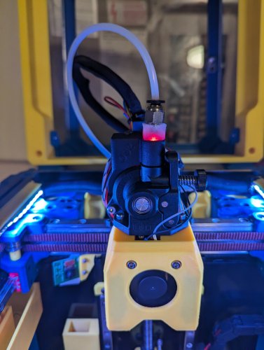
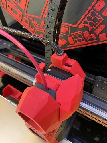
ebb42 mount for cw1 nema17 pancake with umbilical strain relief Decided to go to canbus umbilical for my stealthburner on cw1 and remove both x and y cable chains. As the ebb42 is a new product there had been no mounts that have been released at that time so i came up with this design. The mount sits comfortably on the rear of my extruder nema17 pancake motor and spaces the ebb42 nicely away from the rear of the motor, the m3 motor screws i have are slightly to long so i used spacers on top of the ebb42 to counteract this, also i used a cable strain relief to protect the 4 wires to the ebb42 which the dimentions are 5mm hole, 28mm length, diameter 11.8mm, slot diameter 7.55mm x2.1mm which goes into a little slide in wedge to hold into place and also used expandable braided sleeving size 3-9mm which protects the wires and sits nice and snug in the strain relief. i also modified the original stealthburner cw1 pcb cover by Demosth to fit with this mount (https://www.teamfdm.com/files/file/535-stealthburner-cw1-pcb-cover).- 10 comments
-
- 6
-
-
- stealthburner
- ebb42
- (and 3 more)
-

Version 1.0.0
191 downloads
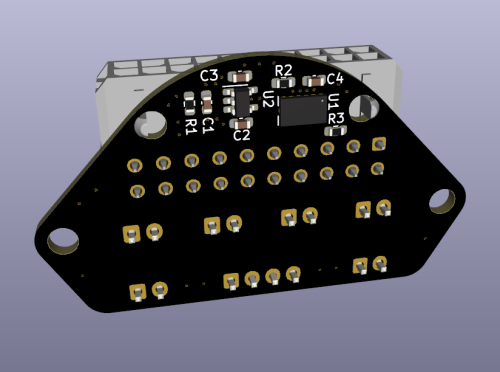
The Voron-0 Umbilical is a well known and very useful addition to your 3D Printer, originally created by GitHub user timmit99 and can be found in the official Voron-Hardware repository here. In this new 'Plus' version, I have added a permanent ADXL345 Accelerometer to the Toolhead board, to make input shaper tuning (and possibly other interesting use-cases) more accessible to users. The Molex MicroFit connector was changed from a 14-pin to 20-pin version to acommodate the additional wires for the ADXL345. The Toolhead PCB can be ordered pre-assembled from JLCPCB (using the included CPL and BOM file) so you do not have to solder the delicate electronics yourself, just the connectors (as you need to do with the original V0-Umbilical). You can find a full README and Photos/CAD/Design data at my github repository: https://github.com/skuep/V0-Umbilical-Plus Frame PCB BOM Part Quantity Notes LCSC Part Number Link 20 Pin Socket 1 MOLEX 430452012 C485575 https://www.lcsc.com/product-detail/Wire-To-Board-Wire-To-Wire-Connector_MOLEX-430452012_C485575.html SMD Thermistor 1 100K 0805 Thermistor C143680 https://lcsc.com/product-detail/NTC-Thermistors_Vishay-Intertech-NTCS0805E3104FXT_C143680.html 2 pin JST XH 5 2.5mm pitch C158012 https://lcsc.com/product-detail/Wire-To-Board-Wire-To-Wire-Connector_JST-Sales-America-B2B-XH-A-LF-SN_C158012.html 3 pin JST XH 2 2.5mm pitch C144394 https://lcsc.com/product-detail/Wire-To-Board-Wire-To-Wire-Connector_JST-Sales-America-B3B-XH-A-LF-SN_C144394.html 4 pin JST XH 3 2.5mm pitch C144395 https://lcsc.com/product-detail/Wire-To-Board-Wire-To-Wire-Connector_JST-Sales-America-B4B-XH-A-LF-SN_C144395.html 6 pin JST XH 1 2.5mm pitch C144397 https://www.lcsc.com/product-detail/Wire-To-Board-Wire-To-Wire-Connector_JST-Sales-America_B6B-XH-A-LF-SN_JST-Sales-America-B6B-XH-A-LF-SN_C144397.html Screw Terminal 1 5.08mm pitch C8465 https://lcsc.com/product-detail/Screw-terminal_Ningbo-Kangnex-Elec-WJ500V-5-08-2P_C8465.html Optional Parts Part Quantity Notes LCSC Part Number Link 0805 10uF Capacitor 3 Use if using BARE neopixel IC's. Strips have these already. C17024 https://lcsc.com/product-detail/Multilayer-Ceramic-Capacitors-MLCC-SMD-SMT_Samsung-Electro-Mechanics-CL21A106KPFNNNE_C17024.html Toolhead PCB BOM Part Quantity Notes LCSC Part Number Link 20 Pin Socket (Right Angle) 1 Molex 430452000 C485576 https://www.lcsc.com/product-detail/Wire-To-Board-Wire-To-Wire-Connector_MOLEX-430452000_C485576.html 2 pin JST XH 6 B2B-XH C158012 https://lcsc.com/product-detail/Wire-To-Board-Wire-To-Wire-Connector_JST-Sales-America-B2B-XH-A-LF-SN_C158012.html 4 pin JST XH 1 B4B-XH C144395 https://lcsc.com/product-detail/Wire-To-Board-Wire-To-Wire-Connector_JST-Sales-America-B4B-XH-A-LF-SN_C144395.html LP2985-33DBVR 1 3.3V LDO C95414 https://www.lcsc.com/product-detail/Linear-Voltage-Regulators-LDO_Texas-Instruments-LP2985-33DBVR_C95414.html ADXL345BCCZ 1 Accelerometer C9667 https://www.lcsc.com/product-detail/Motion-Sensors-Accelerometers_Analog-Devices-ADXL345BCCZ-RL7_C9667.html 10 Ohm Resistor 2 0603 size C22859 https://www.lcsc.com/product-detail/Chip-Resistor-Surface-Mount_UNI-ROYAL-Uniroyal-Elec-0603WAF100JT5E_C22859.html 10 kOhm Resistor 1 0603 size C25804 https://www.lcsc.com/product-detail/Chip-Resistor-Surface-Mount_UNI-ROYAL-Uniroyal-Elec-0603WAF1002T5E_C25804.html 4.7uF Capacitor 2 0603 size C19666 https://www.lcsc.com/product-detail/Multilayer-Ceramic-Capacitors-MLCC-SMD-SMT_Samsung-Electro-Mechanics-CL10A475KO8NNNC_C19666.html 10nF Capacitor 2 0603 size C57112 https://lcsc.com/product-detail/Multilayer-Ceramic-Capacitors-MLCC-SMD-SMT_10nF-103-10-50V_C57112.html/?href=jlc-SMT Corresponding CPL and BOM files are included in the repository. Using these files you can easily get yourself a ready-made assembled PCB from JLCPCB so you don't have to have the skills to solder the fine-pitch and 0603 packages. Umbilical cable The Umbilical cable is a 220-240mm dual ended 20P (2x10) microfit cable. The connectors are wired 1:1 so pin 1 connects to pin 1 and so forth for all 20 pins. Cable BOM Part Quantity Notes LCSC Part Number Link 20 Pin Plug 2 Molex 430252000 C485324 https://lcsc.com/product-detail/Connectors-Housings_MOLEX-430252000_C485324.html Crimps 20 AWG 12 Molex 430300001/430300007 C259786 https://lcsc.com/product-detail/Line-Pressing-Terminals_MOLEX-430300001_C259786.html Crimps 26 AWG 28 Molex 430300004/430300010 C259765 https://lcsc.com/product-detail/Line-Pressing-Terminals_MOLEX-430300004_C259765.html 20AWG Wire 12 220mm Sections PTFE/Silicone/Hefulon for motion rated, PVC could work since it isn't constraind to a cable chain 26AWG Wire 28 MicroFit connectors support two different ranges of conductor thickness using different wire crimp ferrules. I recommend that you realize the stepper motor and heater wires with 20AWG wire (0.5mm²) and the remaining wires in 26AWG wire (0.14mm²) to save on weight and accelerated mass. Hints and Remarks Extruder Stepper Direction The umbilical cable reverses the stepper rotation direction. I.e. you need to invert the DIR pin of the extruder motor in your printer.cfg file. [extruder] .... dir_pin: PB4 # Add ! (or remove ! if already there) before 'PB4' .... Mounting the Toolhead PCB The umbilical toolhead PCB uses heat stake inserts in order to mount it to the motor screws. In some cases (i.e. LDO motors), the extruder motor already has an additional thread, which has to be either removed by drilling the motor holes with a 3mm spiral drill. If you do not want to drill into the motor, you can use M3x10 captive screws, which are unfortunately hard to find. These screws have a narrowed section and a short thread at the tip so they only 'grab' the thread of the heat stake inserts. Additional chamber thermistor on SKR mini V2.0 If you are using the SKR mini V2.0 board and you want to connect the chamber thermistor, you can use Timmit99's expansion board (https://github.com/VoronDesign/Voron-Hardware/tree/master/SKR-Mini_TFT_Thermistor_Board). If you want an easier and faster solution, you can move the Z-STOP endswitch pin and connect it the E0-STOP pin using a simple self-made JST 2-pin to 3-pin adapter (See Photos folder) or by removing the crimp pins from the 2-pin JST and insert them into the housing of a 3-pin JST header. Once the Z-STOP pin is freed up, you can use it for your thermistor. This method needs the following printer.cfg changes: [stepper_z] ... endstop_pin: ^PC15 # Conversion for additional thermistor (use E0-STOP for Z-STOP) ... [temperature_sensor chamber] sensor_type: Generic 3950 sensor_pin: PC2 gcode_id: C pullup_resistor: 10000 Connecting the ADXL345 to a Raspberry Pi The ADXL345 circuit on the toolhead PCB includes a R-C filter and a 3.3V low-dropout regulator to deliver a clean power supply. Thus you can use the official drawings shown in the corresponding docs (https://www.klipper3d.org/Measuring_Resonances.html), with one small change. You need to connect VCC to +5V (Pin 2 or Pin 4) instead of 3.3V (Pin 1) on the Raspberry Pi extension header (See Photos folder). Then follow the official docs for setting the resonance measurement up.