Search the Community
Showing results for tags 'v2.4'.
-


Version 2
2,274 downloads
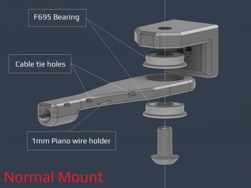
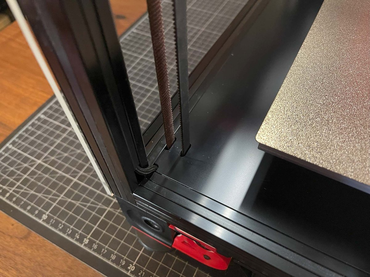
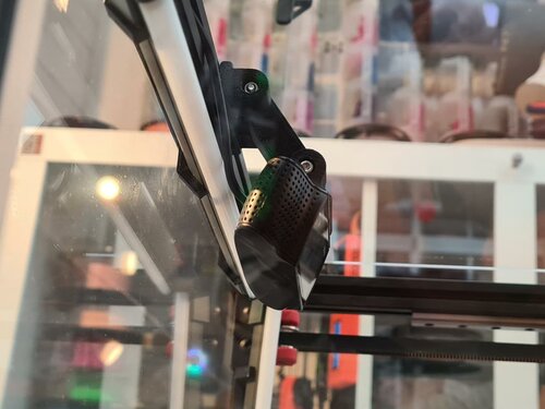
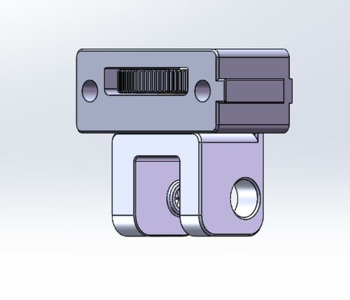
V2- PTFE bowden tube guide and CANBUS wire support I've made some adjustment after some feedback from the community. Changes made over V1: Added a option to have F695 bearings incorporated Enlarged the tube opening Added cable/zip tie openings Added spot for 1mm piano wire if needed. Recommended print settings: Voron print settings (4 walls, 40% infill and 5 top and bottom layers) Turn off thin walls Bridge setting: keep only bridges (watch out for bridging for cable tie holes) 0.2mm layers and 0.2mm first layer No need to adjust for ABS shrinkage Required Hardware: M3x8 Bolt and M3 T-nut M5 bolt to suit option. Optional M5 nut if you can fit it with the bearing option. V1 - PTFE bowden tube guide and CANBUS wire support This is can found inside the zip files and of the initial release Required Hardware: M3x8 Bolt and M3 T-nut M5x10 Bolt or a M5x8/12 Optional 4mm drill bit for cleaning out bowden tube path About In my 350 build the PTFE tube kept getting caught so I made this arm to keep it up. The shorter arm works better so I recommend using it instead The setup has also been used by a few user to support their CANBUS wires (zip tied to the reverse bowden) Install Drill out bowden guide with 4mm drill bit for a perfect fit (optional) Bolt mount to rear frame with M3x8 and tnut putting the lip at the top Screw arm on with M5x10 (I used a M5x8mm and it works fine) into the plastic allowing the arm to still be able to swivel- 3 comments
- 1 review
-
- 13
-

-
- canbus
- galvanicglaze
- (and 3 more)
-
Version 1.2.5
47,488 downloads
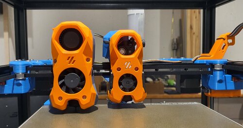
The Mini Stealth v2 toolhead is up on GitHub now. I will keep these files here as the new parts are not compatible with the v1.2.5 parts. I will support both versions in the comments here. I still need to create new assembly instructions but a lot of the steps are similar to what is described here. --------------------------------------------------------------------------- This toolhead scales down the body of the Stealthburner to a size which fits into a V0.1/V0.2. Fully assembled it weighs about 110 grams less than the original. It is designed around the Orbiter 2.0 extruder and has versions for the Phaetus Dragonfly, Dragon and Rapido HF hotends as well as versions for the Mosquito, the Revo Voron and the Creality Spider Pro hotends. It incorporates a status LED as well as two for print visibility. I have added new stretched versions that should fit the Rapido UHF, Dragon UHF and the VolcoMosq hotends. The Dragon UHF and Rapido UHF hotends can fit in the same shroud. The UHF hotends will reduce Z travel by 8.5mm and the VolcoMosq by 3mm. I cannot verify the fitment so if there are any issues please leave a comment. There are now two hex pattern inlays based on the design by 3DP-MAMSIH and a tutorial on how to apply them to the shroud. The negative body feature of Prusa/Super Slicer can also be used to create a crop-top version of the shroud as described at the end of the tutorial. The Mini Stealth uses a pair of 4010 blowers which produce more airflow than a 5015 blower while being notably less noisy and drawing less current. The depth of these fans do limit Y travel by 3mm on a V0.1 while the door is closed and tophat is on. The width of the main body at its base is also a very tight fit at the extremes of X travel. I have raised my tophat by 20mm which gives the cabling and filament tube plenty of room to breathe. The shroud fits a 3010 hotend fan or a 3007 fan by using a clip-in adapter. This Orbiter 2.0 Mini Stealth is a better fit than the Orbiter 1.5 Mini Stealth in a V2.4 or Trident as the motor no longer interferes with the path of the cable chain. There is a separate 'strain_relief' stl for use in the V0.1. There are also x-frame pieces that allow this Mini Stealth to be installed on a Switchwire. The nozzle is moved up by 3mm compared to the official Switchwire due to the stepper motor being so low on the Orbiter extruder but this also allows a BL-Touch to fit into the x-frame pieces. I have included a magnet mount and additional shroud .stl files to make this compatible with the ZeroClick mod. This toolhead also has versions that allow mounting a differential IR sensor. I have removed the mechanical Z endstop on my V0.1 and use the IR probe as an endstop and it has greatly simplified my homing sequence. There are additional x-frame pieces that allow mounting the Beacon3D probe, Euclid or Biqu MicroProbe for a V2.4, Trident or Switchwire. The included Blender file shows the entire assembly complete with screws and should answer most basic questions. Note on MGN-9 installation: The default 2mm x 10 plastic threading screw is too long for mounting the x-axis endstop. An M2 x 8 does the job fine. For mounting to the linear carriage use four M3 x 6 flat-head screws. Note: The MGN carriage shown is an MGN-9H, not the shorter MGN-9C used in the V0.1 mod. Preparation I recommend using a file to lightly remove any printing artifacts on the mating face of the shroud. Use a small file to smooth out the break-off edges of the LED PCB and make sure the LED pockets are clear of 'droopy bits' All three fans will need the wire retention piece clipped so the wires fit into the shroud channels easier. Differential IR Probe Installation The IR Probe needs to be screwed into place with two M2.5x8 FHCS before installing any of the fans, except with the VolcoMosq or UHF hotends where the probe needs to be glued on with CA glue. The Y-offset for this probe is 4mm in front of the nozzle and the X-offset is 32mm. I strongly recommend removing the 3-pin header and soldering wires directly to the probe PCB. When installed the wires will route out from the back of the IR probe cover to then join with the hotend and fan wires. I have included a cover to allow a connector at the probe but the wire management will be less than ideal.. Assembly Instructions After pressing the status LED diffuser into place, install the right part-cooling fan first by feeding the wires through the small hole at the bottom. Then feed the wires for the status LED and hotend fan through before starting to push the LED carrier into position. Carefully push the status LED carrier as far as it will go and press the fan into position while making sure not to pinch the part-cooling fan wires. Then press the remaining LEDs into their slots. (I measure out 35mm of wire to connect these LEDs together) Here is another view also showing where the hotend fan wires fit. Insert the second part-cooling fan and splice the wires together with the first fan. Install the hotend with at least two M2.5x6 screws (M3x6 for the Revo Voron). The heater cartridge should be installed away from the LEDs to avoid overheating them. (** don't forget the PTFE tube) Pre-assemble the extruder pieces before installing into the shroud. Use two M3x8 BHCS to install the Orbiter 2.0 extruder. It helps to have both screws in the Orbiter before putting it in place. Start the screw by the latch and then the blind screw should be easier to align. Gather all of the wires together with a zip-tie next to the base of the Orbiter latch and then use another zip-tie to secure the wires to the motor-bridge. Leave a little slack in the extruder wires. Install the strain_relief or cable_chain_mount with two M3x6/8 screws and the cable_door with a M3x10/12 screw. Close the cable door with a M3x6 BHCS and screw in the extruder tensioning thumb screw. Use two M3x40 BHCS to secure the toolhead to the x-carriage in a V0.1/V0.2. For installation in a Trident or V2.4 use two M3x50 BHCS. Happy Printing!- 651 comments
- 3 reviews
-
- 37
-

-
-

-
- orbiter 2.0
- v0.1
- (and 16 more)
-
Version 1.2.5
23,267 downloads
The Mini Stealth v2 toolhead is up on GitHub now. I will keep these files here as the new parts are not compatible with the v1.2.5 parts. I will support both versions in the comments here. I still need to create new assembly instructions but a lot of the steps are similar to what is described here. --------------------------------------------------------------------------- This toolhead scales down the body of the Stealthburner to a size which fits into a V0.1/2. Fully assembled it weighs less than 260 grams. It is designed around the Mini Sherpa extruder and has versions for the Phaetus Dragonfly, Dragon and Rapido HF hotends as well as versions for the Mosquito, the Revo Voron and the Creality Spider Pro hotends. It incorporates a status LED as well as two for print visibility. I have also added stretched versions that should fit the Rapido UHF, Dragon UHF and the VolcoMosq hotends. The Dragon UHF and Rapido UHF hotends can fit in the same shroud. The UHF hotends will reduce Z travel by 8.5mm and the VolcoMosq by 3mm. I cannot verify the fitment so if there are any issues please leave a comment. There are now two hex pattern inlays based on the design by 3DP-MAMSIH and a tutorial on how to apply them to the shroud. The negative body feature of Prusa/Super Slicer can also be used to create a crop-top version of the shroud as described at the end of the tutorial. The shroud uses a pair of 4010 blowers which produce more airflow than a 5015 blower while also being notably less noisy and drawing less current. The depth of these fans do limit Y travel by 3mm on a V0.1 while the door is closed and tophat is on. The width of the main body at its base is also a very tight fit at the extremes of X travel. The shroud fits a 3010 hotend fan or a 3007 fan by using a clip-in adapter. This Mini Stealth - Mini Sherpa also fits well in a V2.4 or Trident and modified x-frame left and right pieces are included. There are cable chain mounts as well as strain_relief and umbilical_PCB mount for use in the V0.1. There are additional x-frame pieces that allow this Mini Stealth to be installed on a Switchwire. The nozzle is moved up by 3mm compared to the official Switchwire. The x-frame has geometry that allows a BL-Touch to fit locked between the two pieces. I have included a magnet mount and additional shroud .stl files to make this compatible with the ZeroClick mod. This toolhead also has versions that allow mounting a differential IR sensor. I have removed the mechanical Z endstop on my V0.1 and use the IR probe as an endstop and it has greatly simplified my homing sequence. There are additional x-frame pieces that allow mounting the Beacon3D probe, Euclid or Biqu MicroProbe for a V2.4, Trident or Switchwire. The included Blender file shows the entire assembly complete with screws and should answer most basic questions. Note on MGN-9 installation: The default 2mm x 10 plastic threading screw is too long for mounting the x-axis endstop. An M2 x 8 does the job fine. For mounting to the linear carriage use four M3 x 6 flat-head screws. Note: The MGN carriage shown is an MGN-9H, not the shorter MGN-9C used in the V0.1 mod. Preparation I recommend using a file to lightly remove any printing artifacts on the mating face of the shroud. Use a small file to smooth out the break-off edges of the LED PCB and make sure the LED pockets are clear of 'droopy bits' All three fans will need the wire retention piece clipped so the wires fit into the shroud channels easier. Differential IR Probe Installation The IR Probe needs to be screwed into place with two M2.5x8 FHCS before installing any of the fans, except with the VolcoMosq or UHF hotends where the probe needs to be glued on with CA glue. The Y-offset for this probe is 4mm in front of the nozzle and the X-offset is 32mm. I strongly recommend removing the 3-pin header and soldering wires directly to the probe PCB. When installed the wires will route out from the back of the IR probe cover to then join with the hotend and fan wires. I have included a cover to allow a connector at the probe but the wire management will be less than ideal.. Assembly Instructions After pressing the status LED diffuser into place, install the right part-cooling fan first by feeding the wires through the small hole at the bottom. Then feed the wires for the status LED and hotend fan through before starting to push the LED carrier into position. Carefully push the status LED carrier as far as it will go and press the fan into position while making sure not to pinch the part-cooling fan wires. Then press the remaining LEDs into their slots. (I measure out 35mm of wire to connect these LEDs together) Here is another view also showing how the hotend fan wires fit through the hole on the side of the status LED carrier. Insert the second part-cooling fan and splice the wires together with the first fan. Install the hotend with at least two M2.5x6 screws (M3x6 for the Revo Voron). The heater cartridge should be installed away from the LEDs to avoid overheating them. ( ** don't forget the PTFE tube ) Pre-assemble the extruder with your chosen cable management using M3x20 BHCS before installing into the shroud. Install the extruder with two M3x8 BHCS. Make sure that the LED and fan wires route around and exit behind the extruder. They can even fit in the gap below the extruder as shown in the picture. Gather the wires together with zip ties and secure them up to the cable management piece. Do your best to keep them tucked in close at the base of the extruder. I used a temporary zip tie at the top to keep the wires manageable until I installed the toolhead in the printer. The top of the cable door hooks under the back of the shroud and then you can use 2 - M3x6 BHCS to secure the cable door in place. Use two M3x40 BHCS to secure the toolhead to the x-carriage in a V0.1/V0.2. For installation in a Trident or V2.4 use two M3x50 BHCS. Happy Printing!- 75 comments
- 1 review
-
- 23
-
-
-
-
- mini sherpa
- stealthburner
- (and 16 more)
-
Version 1.0.0
646 downloads
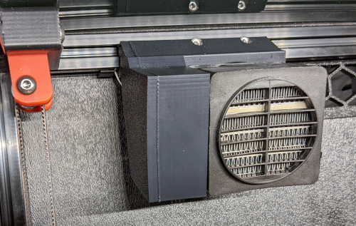
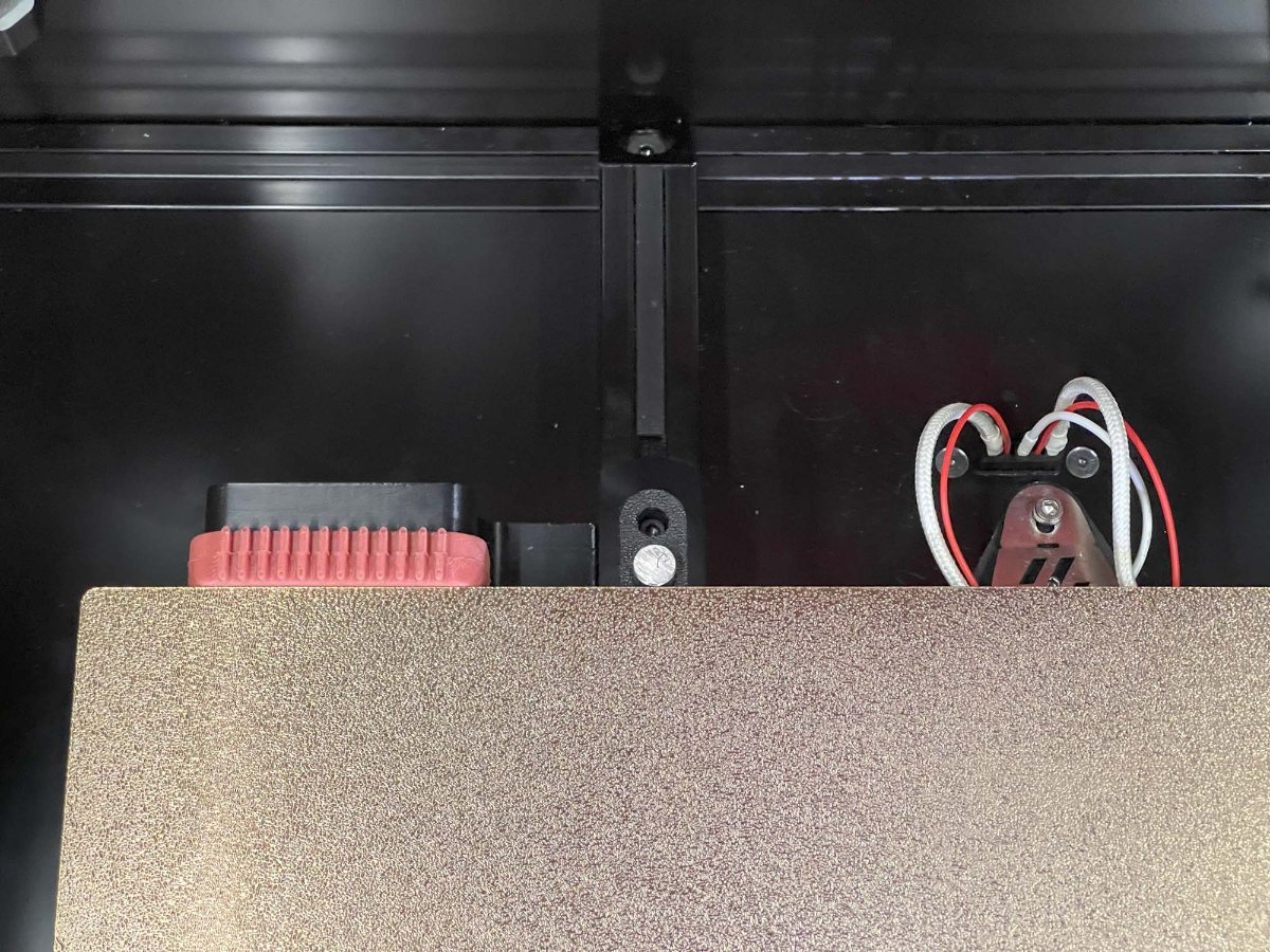
I was having trouble getting my enclosure temperatures above 45C to achieve my optimum print settings. This is the solution I came up with to solve my enclosure temperature issues. I'm running a Fystec Spider v1.1, so your printer config would likely differ. I'm also using a Hartk v4.0 PCB that has an integrated chamber thermistor. I've included my settings for this as well, but you may need to change this up if you use a different thermistor for enclosure temperature readings. I hope this is helpful for someone. I couldn't find a lot of solutions out on the net that could get me up and going with a setup like this, so it was a lot of trial and error to get to this point. Let me know if you have any comments or suggestions that can help me make this thing better! How I set things up: I removed the fan from the PTC heater and inserted a 100K NTC thermistor into one of the bordering fins on the heater core. I then filled the remaining gap in the fin with thermal grease and reattached the fan. I added a thermal fuse to make sure the power would get cut if the temperatures get out of hand from a bad config or faulty piece of hardware. First I drilled a 1/8" hole next to the center ground pin, rivetted the fuse to the heater's core, and applied thermal grease between the fuse body and the heater core. I then moved the ground wire to run from the fuse rather than the tab. Once I wired this up, I ran the temperatures up past the fuse limits to verify things fail safely as expected. I then replaced the fuse after test failed as expected. I extended all of the wiring with solder connections to make sure it would be long enough reach each wire's intended destination, and capped each connection with heat shrink. I mounted the PTC heater to the printed PTC heater mount and ran the wires to the wiring compartment. I installed the Omron relay, and ran a 24v output from my controller to the relay's 5-24v input. I then routed 110v AC to the other end of the relay on the hot lead. I finished up the wiring by hooking up the 12v line for the heater fan and the heater thermistor to the controller board. (Note: my chamber thermistor was already installed on my toolhead's PCB) I updated my printer.cfg and ran a bunch of tests on the heater to make sure it was functioning properly. BOM: Electronics: - PTC Heater w/ Fan x1 - Item on Amazon - NTC 100k thermistor - Item on Amazon - 120C Thermal Fuse - Item on Amazon - Omron 5-24v Relay - Item on West3D Printed Parts: - Printed PTC Heater Mount x1 Miscellaneous: - M3x8mm SHCS x2 - M3 T-nut x2 - 18awg stranded wire ~2 meters - 22awg stranded wire ~2 meters - 1/8" Rivet x1 - Appropriate connectors for you controller board Changes to printer.cfg: ###################### ### Chamber Heater ### ###################### [heater_generic chamber_heater] heater_pin: PC8 sensor_type: Generic 3950 sensor_pin: PC2 control: watermark max_power: .5 min_temp: 0 max_temp: 110 [verify_heater chamber_heater] max_error: 120 check_gain_time: 120 hysteresis: 5 heating_gain: 2 ########################## ### Chamber Heater Fan ### ########################## [heater_fan chamber_heater_fan] pin: PB6 max_power: 1.0 heater: chamber_heater heater_temp: 40.0 # fan will turn off below this level ############################# ### Enclosure Temperature ### ############################# [thermistor chamber_thermistor] temperature1: 25 resistance1: 10000 beta: 3950 [temperature_sensor enclosure_temp] sensor_type: chamber_thermistor sensor_pin: PC1 min_temp: 0 max_temp: 80 Macro: You can run this and immediately start your print. The print wont actually start until the specified chamber temperatures are reached. [gcode_macro CHAMBER_TEMP_WAIT] gcode: {% if params.MIN_TEMPERATURE and params.MAX_TEMPERATURE and params.MIN_TEMPERATURE|float > params.MAX_TEMPERATURE|float %} {action_raise_error("Chamber Temp Wait: MIN_TEMPERATURE must be less than or equal to MAX_TEMPERATURE Use: - CHAMBER_TEMP_WAIT MIN_TEMPERATURE=[0..80] - CHAMBER_TEMP_WAIT MAX_TEMPERATURE=[0..80] - CHAMBER_TEMP_WAIT MIN_TEMPERATURE=[0..80] MAX_TEMPERATURE=[0..80]")} {% elif params.MIN_TEMPERATURE and params.MIN_TEMPERATURE|float > -1 and params.MIN_TEMPERATURE|float < 81 %} {% if params.MAX_TEMPERATURE and params.MAX_TEMPERATURE|float > -1 and params.MAX_TEMPERATURE|float < 81 %} TEMPERATURE_WAIT SENSOR="temperature_sensor enclosure_temp" MINIMUM={params.MIN_TEMPERATURE|float} MAXIMUM={params.MAX_TEMPERATURE|float} {% else %} TEMPERATURE_WAIT SENSOR="temperature_sensor enclosure_temp" MINIMUM={params.MIN_TEMPERATURE|float} {% endif %} {% elif params.MAX_TEMPERATURE and params.MAX_TEMPERATURE|float > -1 and params.MAX_TEMPERATURE|float < 81 %} TEMPERATURE_WAIT SENSOR="temperature_sensor enclosure_temp" MAXIMUM={params.MAX_TEMPERATURE|float} {% else %} {action_raise_error("Chamber Temp Wait: invalid usage Use: - CHAMBER_TEMP_WAIT MIN_TEMPERATURE=[0..80] - CHAMBER_TEMP_WAIT MAX_TEMPERATURE=[0..80] - CHAMBER_TEMP_WAIT MIN_TEMPERATURE=[0..80] MAX_TEMPERATURE=[0..80]")} {% endif %} Updates: - I added a photo of how this is wired up in the wiring compartment. The boxes with the text in the photo represent the components of the heater that are in the chamber of the printer. - I have included the macro to wait for chamber to reach temps before starting a print. - I have attached the heater mount's fusion 360 file for others to be able to easily make edits to the chamber heater mount Chamber Heater Mount v2.f3d- 93 comments
- 2 reviews
-
- 42
-
-
-
-
- chamber heater
- heater
- (and 1 more)
-
Version 1.0.0
2,505 downloads
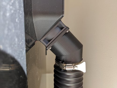
I wanted to be able to print ABS and ASA in my house without having to move my printer to a well ventilated area, so I started looking into ventilation options. I wasn't able to find anything that seemed to mount cleanly to my machine and look decent running to my window, so I designed this system for my printer. BOM: Parts to order 2.5" Hose Clamps x2 2.5" Flexible Dust Collector Hose (3ft in picture) x1 Weather Stripping (10ft in picture) M2 self-tapping screw Plastic Sheet (1.5mm-2mm) Parts to Print 60mm Fan to 2.5" Hose Adaptor x1 Hose Adaptor x1 Hose Adaptor Mount x1 One-way Valve x1 Left Link x1 Right Link x1 Center Link x? (You will need to measure your window for the proper number of links) Printing: 40% infill Supports needed 4 line walls Filament: Polymaker's Polylite ASA If you are using the stock Voron 2.4 exhaust system, you can attach the hose adaptor directly to the rear fan using the screws already holding the fan in place. All of the links snap very tightly together and may require pliers to fully seat the lock. You can also insert the one way valve into the hose adapter on the window side of the hose: Then just attach all of the other pieces according to the images below: Once you have everything hooked together your can wrap the window vent that is now sized for your window with the weather stripping to get a good seal on your window. One note, I was printing several test versions of this before I got to a full system. There are couple links you will see in the center of my image that have a smaller lip on them. I just reused these from previous test pieces so I didn't waste more plastic. Your center links should be consistent all the way across the middle section of the window vent. UPDATE: 3/9/2022 - Added a one-way valve to prevent outside air from causing a backdraft into your printer when your exhaust fan is disabled. This has made a significant impact on reducing plastic fumes in my house. After adding this, I can't smell any plastic unless the doors on the printer are open. VORON2 v2.4 - 2.5 Vaccume exhaust adapter v4.f3d- 21 comments
-
- 16
-
-
-
-

-
Version 2022.03.31
16,048 downloads
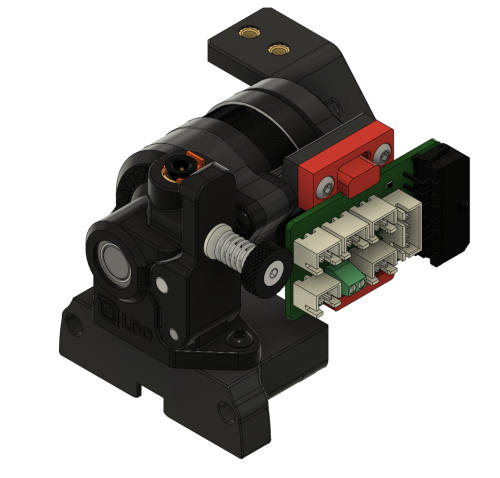
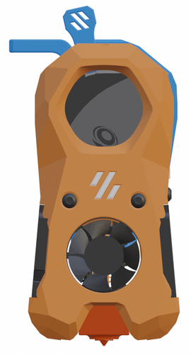
Orbiter 2 Clockwork Module (beta) This Clockwork module allows the use of the Orbiter v2 Extruder in the Voron Afterburner. THIS IS A PRE-RELEASE - DO NOT DOWNLOAD UNLESS YOU ARE WILLING TO DEAL WITH POSSIBLE ISSUE OR TO GIVE FEEDBACK! The rear screws that hold the chain anchor on are m3x8, two of them. They use the Voron heat set inserts, m3 I was working with DoubleT on the PCB holder. Trying to build a universal tool version so we could use different holders.- 84 comments
-
- 22
-
-
-
-
- orbiter2
- spacelab2021
- (and 4 more)
-
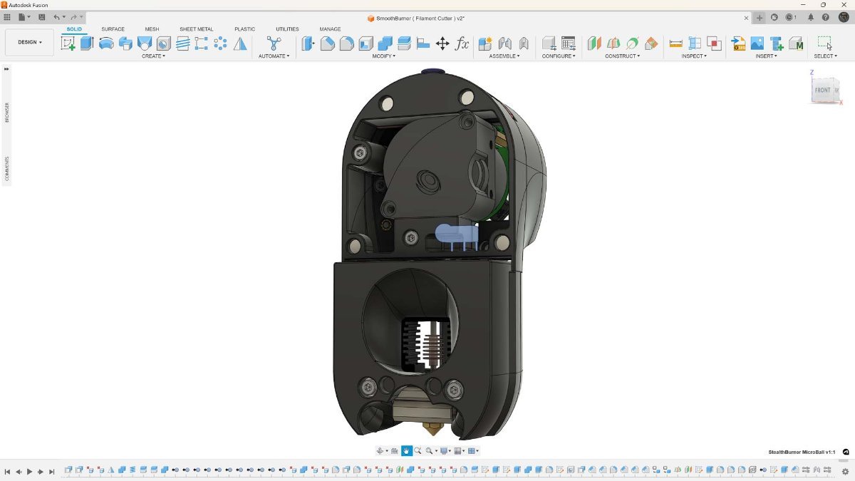
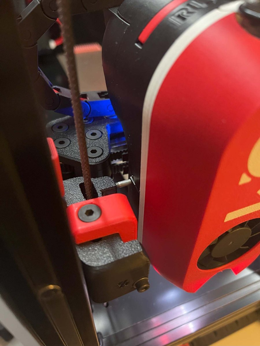
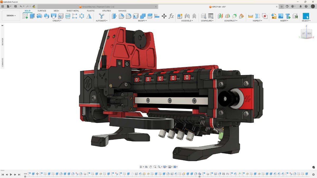
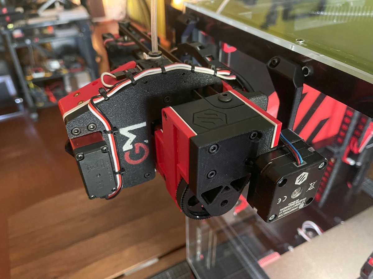
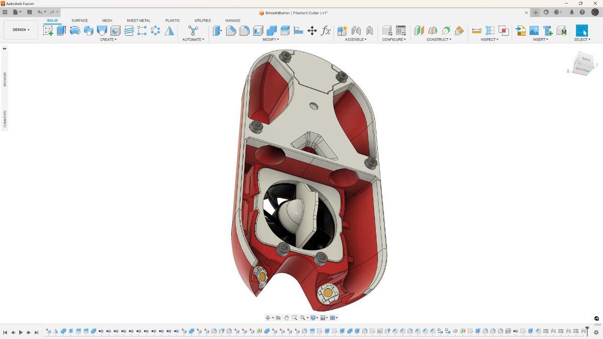
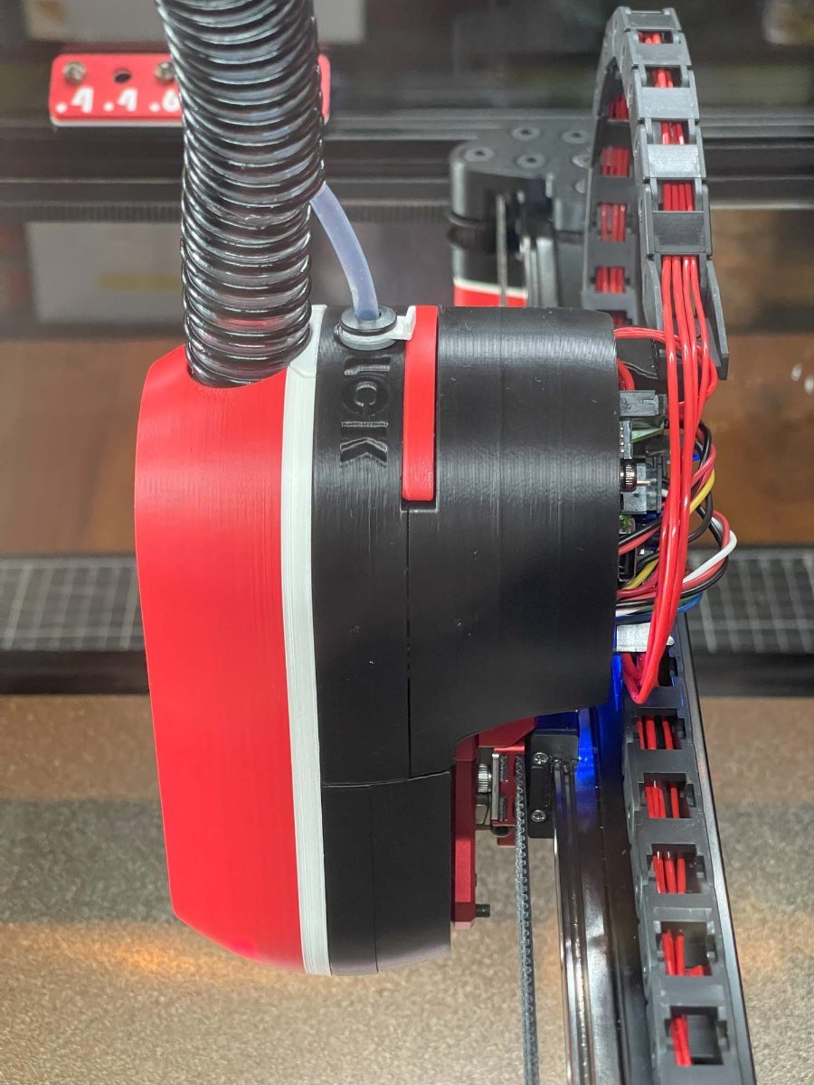
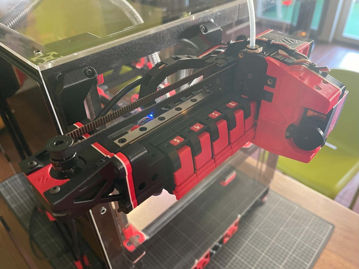
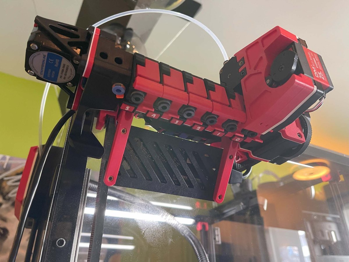
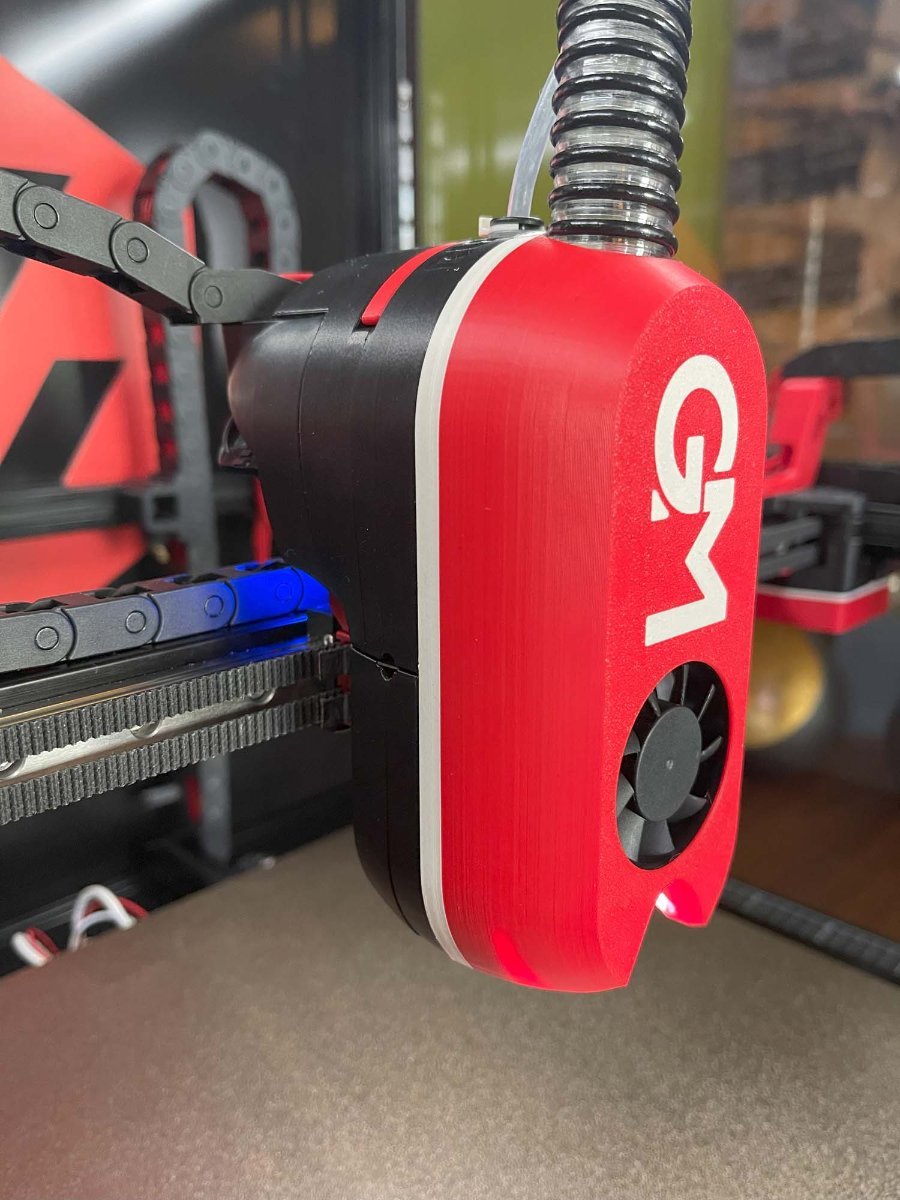
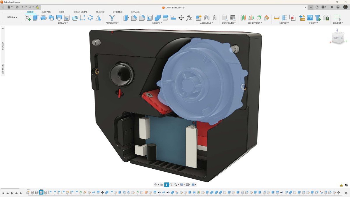
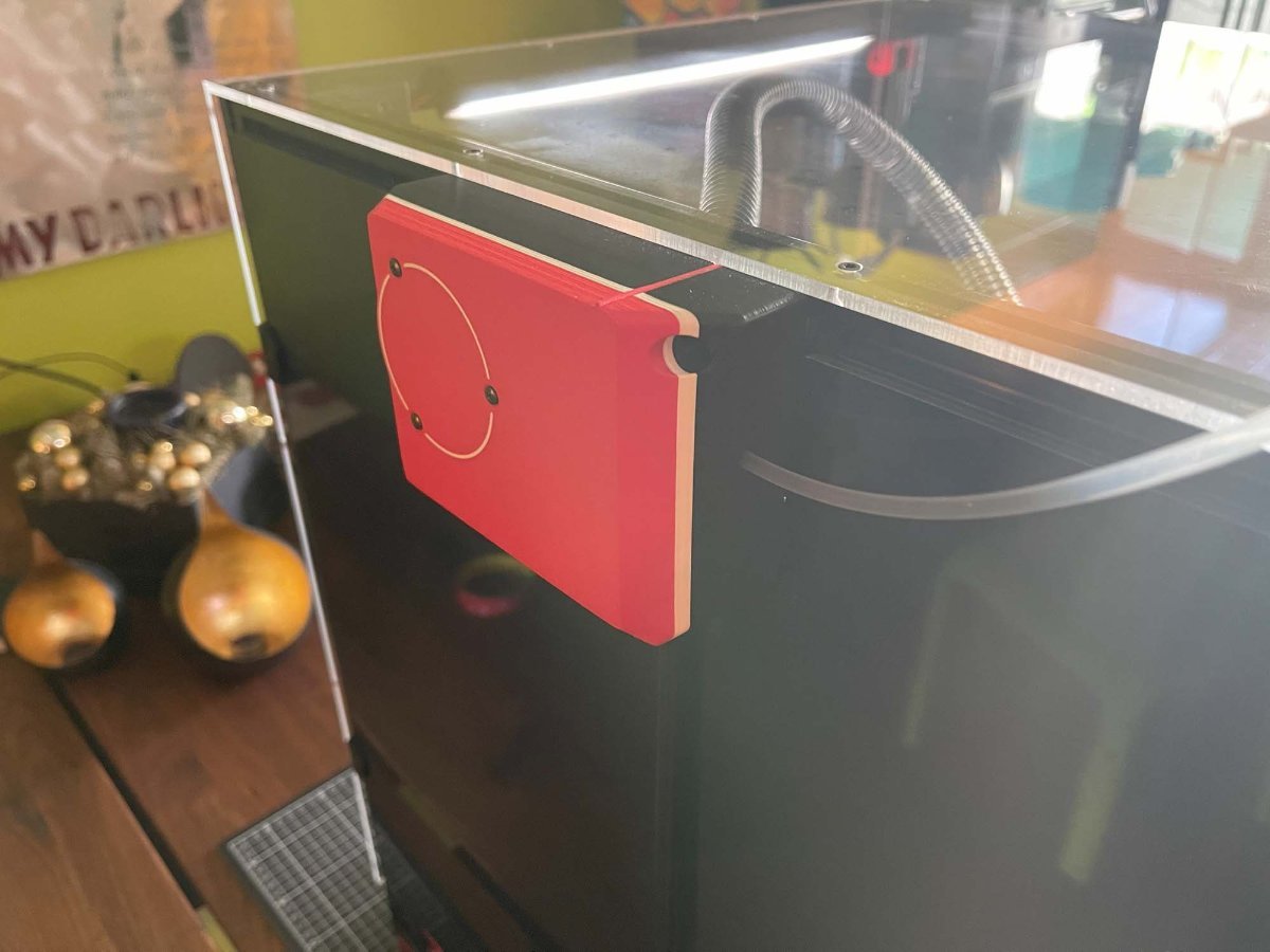
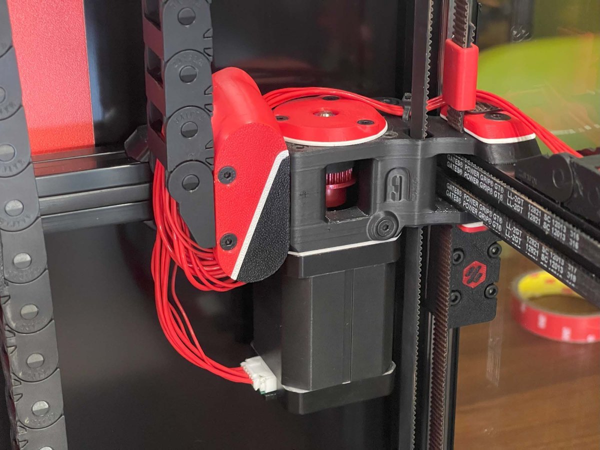
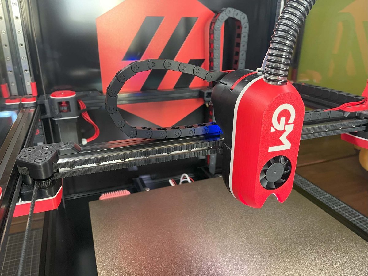
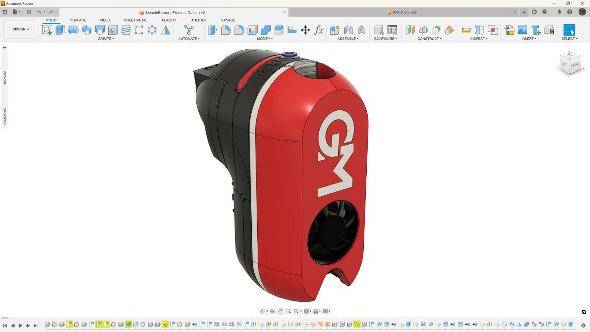
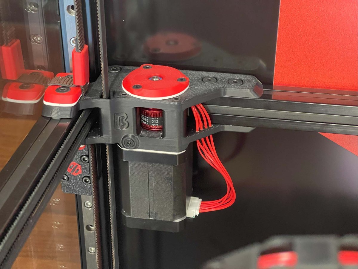
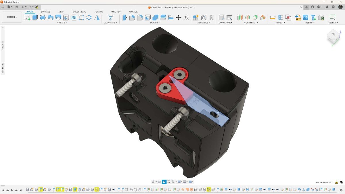
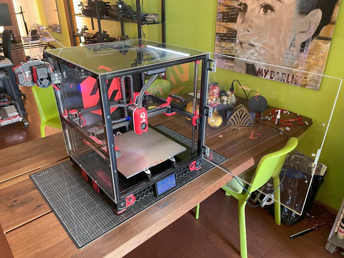
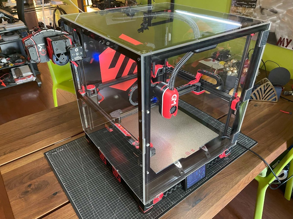
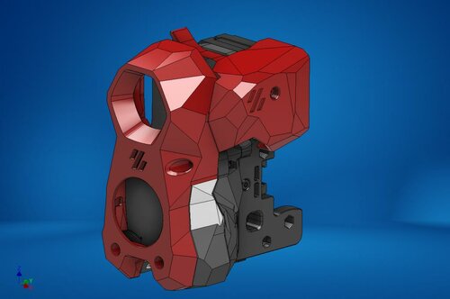
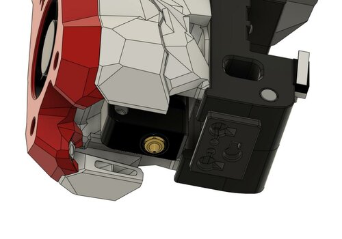
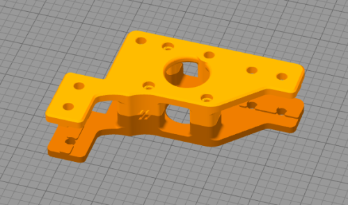
A Gallery of my 350 sized V2.4 Crystal Prison The Build started out as your run of the mill end of 2021 Formbot Kit but has gradually been upgraded with higher quality Components and mostly self-designed / redesigned MODs. A big part of the current concept was getting rid of the unsightly Panel Clips which I've done away with by attaching the 4mm Acrylic Panels directly onto the Frame ( with 3D Printed Spacers where necessary ) using Flathead Screws with the Sides overlapping the Top and the Door overlapping the Top and Sides for practically seamless Glass Cube look - Hence the Name Crystal Prison. The front 8mm Acrylic Door required additional CNCed Pockets for the flush mounted look of the three 90° Print in Place Hinges and recessed "Handle". All of the original Gantry Parts have been redesigned for a more streamlined look utilizing Ultra Low-Profile Socket Head Cap Screws. Meanwhile the SmoothBurner named Tool Head has been reconfigured to a CPAP Design without the StealthBurner faceted look I couldn't care for. The overall Dimensions and weight are slightly bigger than that of a StealthBurner but cause no issues with the geometry of the Gantry - As such there's no loss in Print Volume. The Front Cover attaches magnetically to the rest of the Tool Head via Screws being attracted to recessed Magnets with the former also acting as registration Pins preventing the Front from shifting ( the front can only be re/moved by pulling it towards the front ). The Wiring during assembly is a Pain in the Ass as neither the LEDs nor the Connectors fit through the Channels requiring Soldering within a partially assembled Front. Barely visible is the Tool Head Cutter Port situated behind the Front Cover and in-between the Extruder and Part Cooling Section. The Cutting is done by a Type 11 Blade with the Reset Function accomplished by a 1x40mm Spring Steel Wire sandwiched between the Part Cooling Halves. The in the B-Idlers installed Cutting Pin made out of a decapitated M3 Screw. The Reverse Bowden Tube exiting out of the CPAP Tube - While not yet fully realized yet it is planned to use this feature to keep temperature sensitive Filaments like PLA cool until they've reached the Tool Head while printing them together with high Temperature Materials like ASA. Also nicely visible is the red Filament Tension Lever for the Bondtech LGX Lite in its normal / centered position ( left being open, right being soft materials ). The Tool Head with the Front removed - Much of its design came from Eytecz LGX Lite Design featuring an ERCF necessary Tool Head Sensor utilizing a Washer / MicroSwitch Combo. New A / B-Drives for the LDO-42STH60-3004MAC (S40) "Kraken" Stepper Motors using 30T Pulleys - While not shown in these Pictures I've since had to add active Cooling Fans to them as otherweise they'd reach temperatures beyond their Insulation Class B rating. The new Drives also come with Shaft Support Bearings at the Top. B-Drive Side with integrated Cable Management Passthroughs routing them to the Back Extrusion Channel and to the A-Side ( covered underneath an Extrusion Channel Cover ). CNCed Minimal Clearance Z-Axis Belt and Cable Passthroughs. To the left a self-made High Temperature Silicone Nozzle Brush, in the center one of the two 8mm Bed Surface Alignment Pins, and to the right the Bed Heater Deck Panel Connector. A custom variant of the CarlosRodriguess ERCF-M but using my Large Servo MOD with the latter having enough force to break the Side Latch on the Original ERCF Design. Different View showing the Excentric CAM Wheel attached to the Servo operating a Spring-Loaded Stylus for a Springy like effect and my own Top Hat Design for the Kieraneglin Thumper Blocks. Underslung BigTreeTech MMB CAN Board providing maximum cooling and protection. CAD Model of the ERCF-M - I had initially only decided to redo the Selector portion for adding the Large Servo MOD but in the end went full retard and modelled everything. The CPAP Housing with the PTFE Tube being injected into it. The Housing houses everything and comes with the option to divert part of the Air Stream over the FANs Control Board by removing the small ( red ) Gate below the Exhaust Port. In a surprising happenstance the Housing paired with the thicker than usual Acrylic Panel seems to provide a fair bit of Noise dampening against the CPAP A short Video of it.
-
Version 2021.10.09
150 downloads
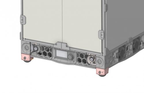
What are Panzerballs? Panzerballs are another type of feet using commonly available squash balls. Why do they exist? i hate sourcing of rubber compressor feet i felt that other squash ball mods do not satisfy me visually (sry) Why do i need Panzerballs? You probably don´t need them unless you got problems with sourcing the normal rubber compressor feet or you want something more squishy with maybe a better noise reduction. How do i install Panzerballs? Panzerballs are a drop in replacement for the base plate You need: 4x squash balls (super slow, double yellow dot, diameter 39.5-40.5 mm) o german source:https://www.decathlon.de/p/squashballe-sb-990-2er-pack-zwei-gelbe-punkte/_/R-p-312192 4x printed Panzerballs: o Use '01-Normal/[a]_PanzerBall_x4.stl' if you have not modded your z-Drive o If you use edwardyeeks V2.4_z_drive_tensioner_mod is also supported: install the Panzerballs from folder '02-Optional_z-Drive-Mod/*.stl' Screws as Voron Spec build Credits go to edwardyeeks. -
Version 1.0.0
125 downloads
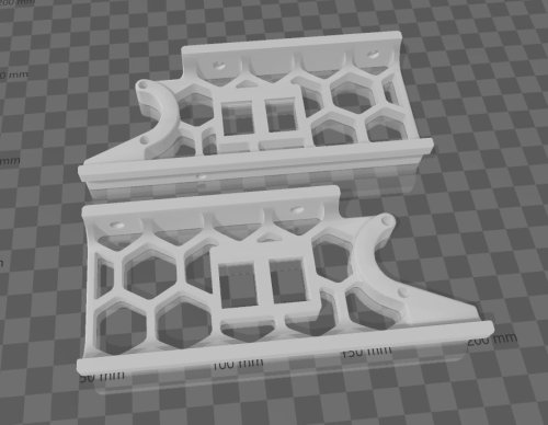
Front Skirts with Keystone Opening for Voron V2.4 350 -
Version 2021.12.07
732 downloads
Angry CAM USB Please find my USB Camera Mod based on Waveshare OV5648 5MP USB Camera Module (A), which allows mounting to rear gantry or other position on a frame profile. Printing Printing succesful with standard VORON settings. Distance between mounts and camera housing set to 0.3 mm in *.stl file, which allows printing of mounts and housing in one print. Use the following two *.stl files for realization in one print: Camera_Housing Mounts.stl Rear_Cover.stl Additional Material Bill of Material: 1x Waveshare OV5648 5 MP Camera Module (A), incl. USB-A to JST SH PCB connector cable 2x M3x16 SHCS screws 2x M3 T-Nut for 2020 frame profile 1x Camera Housing Mounts and Rear Cover from the printing source of your trust. Optional/Required for frame sizes -
Version 1.2.5
22,368 downloads
The Mini Stealth v2 toolhead is up on GitHub now. I will keep these files here as the new parts are not compatible with the v1.2.5 parts. I will support both versions in the comments here. I still need to create new assembly instructions but a lot of the steps are similar to what is described here. --------------------------------------------------------------------------- This toolhead scales down the body of the Stealthburner to a size which fits into a V0.1/V0.2. Fully assembled it weighs about 120 grams less than the original. It is designed around the Bondtech LGX Lite extruder and has versions for the Phaetus Dragonfly, Dragon and Rapido HF hotends as well as versions for the Mosquito, the Revo Voron and the Creality Spider Pro hotends. It incorporates a status LED as well as two for print visibility. I have added new stretched versions that should fit the Rapido UHF, Dragon UHF and the VolcoMosq hotends. The Dragon UHF and Rapido UHF hotends can fit in the same shroud. The UHF hotends will reduce Z travel by 8.5mm and the VolcoMosq by 3mm. I cannot verify the fitment so if there are any issues please leave a comment. There are now two hex pattern inlays based on the design by 3DP-MAMSIH and a tutorial on how to apply them to the shroud. The negative body feature of Prusa/Super Slicer can also be used to create a crop-top version of the shroud as described at the end of the tutorial. The shroud uses a pair of 4010 blowers which produce more airflow than a 5015 blower while also being notably less noisy and drawing less current. The depth of these fans do limit Y travel by 3mm on a V0.1 while the door is closed and tophat is on. The width of the main body at its base is also a very tight fit at the extremes of X travel. The shroud fits a 3010 hotend fan or a 3007 fan by using a clip-in adapter. The Mini Stealth LGX Lite fits well in a V2.4 or Trident and modified x-frame left and right pieces are included. There is a separate 'strain_relief' stl for use in the V0.1. There are also x-frame pieces that allow this Mini Stealth to be installed on a Switchwire. The nozzle is moved up by 3mm compared to the official Switchwire. The x-frame has geometry that allows a BL-Touch to fit locked between the two pieces. I have included a magnet mount and additional shroud .stl files to make this compatible with the ZeroClick mod. This toolhead also has versions that allow mounting a differential IR sensor. I have removed the mechanical Z endstop on my V0.1 and use the IR probe as an endstop and it has greatly simplified my homing sequence. There are additional x-frame pieces that allow mounting the Beacon3D probe, Euclid or Biqu MicroProbe for a V2.4, Trident or Switchwire. The included Blender file shows the entire assembly complete with screws and should answer most basic questions. Note on MGN-9 installation: The default 2mm x 10 plastic threading screw is too long for mounting the x-axis endstop. An M2 x 8 does the job fine. For mounting to the linear carriage use four M3 x 6 flat-head screws. Note: The MGN carriage shown is an MGN-9H, not the shorter MGN-9C used in the V0.1 mod. Preparation I recommend test fitting the extruder, LGX_lite_adapter_plate, PTFE tube and hotend into the shroud before running any wires to ensure that the PTFE tube length is correct and everything fits. It helps to chamfer the edge of the tube with a sharp blade so that it doesn't snag in the hotend. I is a good idea to use a file to lightly remove any printing artifacts on the mating face of the shroud. All three fans will need the wire retention piece clipped so the wires fit into the shroud channels easier. Use a small file to smooth out the break-off edges of the LED PCB and make sure the LED pockets are clear of 'droopy bits' Differential IR Probe Installation The IR Probe needs to be screwed into place with two M2.5x8 FHCS before installing any of the fans, except with the VolcoMosq or UHF hotends where the probe needs to be glued on with CA glue. The Y-offset for this probe is 4mm in front of the nozzle and the X-offset is 32mm. I strongly recommend removing the 3-pin header and soldering wires directly to the probe PCB. When installed the wires will route out from the back of the IR probe cover to then join with the hotend and fan wires. I have included a cover to allow a connector at the probe but the wire management will be less than ideal.. Assembly Instructions After pressing the status LED diffuser into place, install the right part-cooling fan first by feeding the wires through the small hole at the bottom. Then feed the wires for the status LED and hotend fan through before starting to push the LED carrier into position. Carefully push the status LED carrier as far as it will go and press the fan into position while making sure not to pinch the part-cooling fan wires. Then press the remaining LEDs into their slots. (I measure out 35mm of wire to connect these LEDs together) Here is another view also showing how the hotend fan wires fit through the hole on the side of the status LED carrier. Insert the second part-cooling fan and splice the wires together with the first fan. Install the hotend with at least two M2.5x6 screws (M3x6 for the Revo Voron). The heater cartridge should be installed away from the LEDs to avoid overheating them. ( ** don't forget the PTFE tube ) Pre-assemble the extruder pieces before installing into the shroud. Use M3x30 screws to attach motor_bridge. Install the extruder with an M3x6 BHCS on the back and then an M3x12 from below. Ensure the cables are routed as flat to the shroud as possible and secure them with zip ties. Install the strain_relief or cable_chain_mount with two M3x8 screws and the cable_door with another M3x8 screw. Close the cable door with an M3x6 screw. Use two M3x40 BHCS to secure the toolhead to the x-carriage in a V0.1/V0.2. For installation in a Trident or V2.4 use two M3x50 BHCS. Happy Printing!- 180 comments
-
- 23
-
-
-
- lgx lite
- stealthburner
- (and 19 more)
-
Version 1.2.5
13,614 downloads
The Mini Stealth v2 toolhead is up on GitHub now. I will keep these files here as the new parts are not compatible with the v1.2.5 parts. I will support both versions in the comments here. I still need to create new assembly instructions but a lot of the steps are similar to what is described here. --------------------------------------------------------------------------- This toolhead scales down the body of the Stealthburner to a size which fits into a V0.1/V0.2. Fully assembled it weighs about 80 grams less than the original. It is designed around the Orbiter 1.5 extruder and has versions for the Phaetus Dragonfly, Dragon and Rapido HF hotends as well as versions for the Mosquito and the Revo Voron hotends. It incorporates a status LED as well as two for print visibility. There are now two hex pattern inlays based on the design by 3DP-MAMSIH and a tutorial on how to apply them to the shroud. The negative body feature of Prusa/Super Slicer can also be used to create a crop-top version of the shroud as described at the end of the tutorial. I have added new stretched versions that should fit the Rapido UHF, Dragon UHF and the VolcoMosq hotends. The Dragon UHF and Rapido UHF hotends can fit in the same shroud. The UHF hotends will reduce Z travel by 8.5mm and the VolcoMosq by 3mm. I cannot verify the fitment so if there are any issues please leave a comment. It uses a pair of 4010 blowers which I found to produce more airflow than a 5015 blower while being notably less noisy and drawing less current. The depth of these fans do limit Y travel by 3mm on a V0.1 while the door is closed and tophat is on. The width of the main body at its base is also a very tight fit at the extremes of X travel. I have raised my tophat by 20mm which gives the cabling and filament tube plenty of room to breathe. The shroud fits a 3010 hotend fan or a 3007 fan by using a clip-in adapter. I have also installed this on my Trident. The included files do not address cable management on a Trident or V2.4 but do provide mounting to the MGN12 carriage. The cable chain on a Trident or V2.4 would have to be moved back at least 5mm to clear the extruder stepper motor. There is a separate 'strain_relief' stl for use in the V0.1. There are also x-frame pieces that allow this Mini Stealth to be installed on a Switchwire. The nozzle is moved up by 3mm compared to the official Switchwire due to the stepper motor being so low on the Orbiter extruder but this also allows a BL-Touch to fit into the x-frame pieces. I have included a magnet mount and additional shroud .stl files to make this compatible with the ZeroClick mod. This toolhead also has versions that allow mounting a differential IR sensor. I have removed the mechanical Z endstop on my V0.1 and use the IR probe as an endstop and it has greatly simplified my homing sequence. There are additional x-frame pieces that allow mounting the Beacon3D probe, Euclid or Biqu MicroProbe for a V2.4, Trident or Switchwire. The included Blender file shows the entire assembly complete with screws and should answer most basic questions. Note on MGN-9 installation: The default 2mm x 10 plastic threading screw is too long for mounting the x-axis endstop. An M2 x 8 does the job fine. For mounting to the linear carriage use four M3 x 6 flat-head screws. Note: The MGN carriage shown is an MGN-9H, not the shorter MGN-9C used in the V0.1 mod. Preparation I recommend using a file to lightly remove any printing artifacts on the mating face of the shroud. Use a small file to smooth out the break-off edges of the LED PCB and make sure the LED pockets are clear of 'droopy bits' All three fans will need the wire retention piece clipped so the wires fit into the shroud channels easier. Differential IR Probe Installation The IR Probe needs to be screwed into place with two M2.5x8 FHCS before installing any of the fans, except with the VolcoMosq or UHF hotends where the probe needs to be glued on with CA glue. The Y-offset for this probe is 4mm in front of the nozzle and the X-offset is 32mm. I strongly recommend removing the 3-pin header and soldering wires directly to the probe PCB. When installed the wires will route out from the back of the IR probe cover to then join with the hotend and fan wires. I have included a cover to allow a connector at the probe but the wire management will be less than ideal.. Assembly Instructions After pressing the status LED diffuser into place, install the right part-cooling fan first by feeding the wires through the small hole at the bottom. Then feed the wires for the status LED and hotend fan through before starting to push the LED carrier into position. Carefully push the status LED carrier as far as it will go and press the fan into position while making sure not to pinch the part-cooling fan wires. Then press the remaining LEDs into their slots. (I measure out 35mm of wire to connect these LEDs together) Here is another view also showing where the hotend fan wires fit. Insert the second part-cooling fan and splice the wires together with the first fan. Install the hotend with at least two M2.5x6 screws (M3x6 for the Revo Voron). The heater cartridge should be installed away from the LEDs to avoid overheating them. ( ** don't forget the PTFE tube ) Gather the wires together and secure them with the first zip-tie. (it helps to insert a snipped zip-tie through the the hole and yank it through with pliers to remove printing artifacts from inside of the channels) Loop the wire bundle back around and add in the LED and hotend fan wires. Use two more zip-ties to secure everything in place. ENSURE to leave room for the extruder by lifting the loop of wires up and out of the way as shown. More space is much better than not enough. (Don't forget the PTFE tube) Pre-assemble the extruder pieces before installing into the shroud. Use two M3x8 BHCS to install the Orbiter 1.5 extruder. It helps to have both screws in the Orbiter before putting it in place. Start the screw by the latch and then the blind screw should be easier to align. Gather all of the wires together and then use a zip-tie to secure them to the motor-bridge. Leave a little slack in the extruder wires. Install the strain_relief with two M3x6/8 screws and the cable_door with a M3x10/12 screw. Close the cable door with a M3x6 screw and screw in the extruder tensioning thumb screw. Use two M3x40 BHCS to secure the toolhead to the x-carriage in a V0.1/V0.2. For installation in a Trident or V2.4 use two M3x50 BHCS. Happy Printing!- 43 comments
-
- 13
-
-
-
-
I have a v2.4 with a stealthburner, and I think the biggest problem the printer has is the cooling, which seriously limits my print speed. I've been interested in improving the cooling, and wondered if anyone had any suggestions. My stealthburner uses a regular LGX, mosquito magnum hotend, and the Voron TAP, in case those affect anything.
-
So Black Friday kind of put the nail in the coffin for me. Printed Solid had some KILLER deals, like the complete 7 motor set from LDO (includes the high temp A/B) motors for $69.97!!. So I splurged and bought most of the parts, with the majority coming from West3D (they are less then 5 miles from my house!). PS was out of the LDO black frame kit, so I opted for space gray (again, couldn't not get it for only $87.50!), plus my V0 is space gray and I've taken a liking to it. Now the wait begins....mostly for the overseas parts (Manta M8P w/ Pi 1.2 and steppers), and misc items. I told my wife this will be the third and final printer. Lol, time will only tell.... Furiously printing most of the parts on my V0, with the obvious larger parts printing on my Switchwire. My "mods" will include - Kinematic bed - Using stainless steel since I've read the titanium is mostly for looks and doesn't add value to the 'taco bed' solution (please correct me if I'm wrong) - Titanium backers (again a steal at West3D during their Black Friday sale) - Sexbolt, but the little bit larger one to accommodate for the kinematic mod: https://github.com/tanaes/whopping_Voron_mods/tree/main/kinematic_bed and https://github.com/tanaes/whopping_Voron_mods/blob/main/kinematic_bed/STLs/sexybolt_owo.stl - GE5C - Pinmod - using stainless steel here, didn't want to pony up more $ for aluminum (read: I'm cheap) - Canbus - BTT EBB SB2209 w/ RPi2040 - I have read about the thermistor having issues on the ST version of this, again correct me if I'm wrong
-

Version 1.0.0
187 downloads
CatPaw is the ideal toolhead for Voron Zero series with Orbiter 2.0 Extruder. I developed this toolhead as I was unhappy with the existing options. The standard Voron Zero 0.2 toolhead does not provide as much cooling as I prefer, and certainly less than the StealthBurner toolhead. My design goals were also minimum loss of print volume and maximum compatibility with toolheads and options for probe and filament sensor. CATPAW: Uses Voron Zero 0.2 toolhead cartridges, so should work with all toolheads for voron Zero 0.2 (fan saver recommended) 2x 4010 Blowers, with StealthBurner duct layout for near arctic level part cooling (2x 4010 provides more air than StealthBurner toolhead) Almost no loss in print volume. X axis should be full width, loss off a millimeter or so on X if you print with your door closed. (Magnets on my door are strong enough, so the door closes again if the toolhead bumps into it, giving me the full 120x120 mm even when printing ABS Option to add the slideswipe Probe. I shortened the probe, but all other parts can be used from https://github.com/SaltyPaws/Voron_0.1and0.2mods/SlideSwipe or original repo (https://github.com/chestwood96/SlideSwipe) Option to add under extruder filament Sensor Carriages are provided for MGN7 and MGN9 X-axis rails. It is recommended to print the provided X carriage for the appropriate rail. In order to minimize toolhead height, I lowered the screw hole for the rear mounting screw. The CATPAW toolhead will work with the stock Voron Zero 0.2 Carriage, but the screw securing the X-carriage from the rear will not fit. https://github.com/SaltyPaws/CATPAW_toolhead/raw/main/images/PXL_20240101_224037977.jpg?raw=true BOM 2x SHCS (preferred) or BHSC M3x25 bolt 3x M3 nut 2x NeoPixel 1x 3010 hotend fan 2x 4010 Blower 6x3mm magnets for probe (optional) 6mm steel ball for filament sensor (optional) Omron D2F-L micro-switch with lever for filament sensor (optional) 2x M2x12 or self-tapping screw to secure micro-switch (optional) Installation Instructions Assembly should be done in the following order: Probe Solder wires to 6x3mm magnets. In order to prevent loss of magnetism, let the magnets cool against another 6x3 magnet. Press the magnets into the slots by pushing the toolhead down on a hard object. Use a large flat soldering tip at around 230C to push the magnets deeper into the slots, you want the magnets to stick out ~0.5 to 1 mm. Again, let the magnets cool down attached to other magnets to prevent loss of magnetism. Ensure wire to magnet path has very low resistance (less than 4 ohm). route wires out trough little side window. Seal hole with red gasket maker. NeoPixels Create a chain of 2 neopixels. You do not have a lot of space to hide excess cable, so make the wires between the neopixels as short as possible, while still allowing them to slide into the slots. Test the neopixels! It will be more rework to remove the hotend fan and part cooling fans later. Fans First install 3010 part cooling fan. Be very careful to only press the edges of the fan, the fan will break when pushing the center of the fan (ask me how I know...) Then proceed with installing the blower fans. Use a knife to cut the upper right hand side of the blower fan (looking back to front). This is required for routing the majority of the wires. I used superglue to keep the fan together as you will remove a fan closing latch. I accidentally cut int the fanbox, and sealed up the hole with red gasket maker. For details - see pictures below: https://github.com/SaltyPaws/CATPAW_toolhead/raw/main/images/PXL_20231225_175242278.jpg?raw=true https://github.com/SaltyPaws/CATPAW_toolhead/raw/main/images/PXL_20231225_175256608.jpg?raw=true https://github.com/SaltyPaws/CATPAW_toolhead/raw/main/images/PXL_20231225_175325632.jpg?raw=true Toolhead Cardridge Ensure the heater wires are installed pointing towards the right hand fan that has space for wire routing. Thermistor, probe and fan wires will fit on the other side (left hand side fan). Hold off on installing the zip-ties, these are best installed after the toolhead is installed on the carriage. Filament Sensor Solder wires to filament sensor (2 outer most legs). You may want to shorten the legs somewhat for an easier fit. Trim lever, so that lever does not extend past micro-switch body Install micro-switch and ball Test sensor Install Toolhead Carefully mount toolhead, ensuring that wires are not pinched, and belt is not rubbing on gantry. The bulk of the wires will go in the gap carved out on the right hand side fan, the other side will have sufficient space for probe and fan wires. Min Probe See installation instructions in orignal repo: https://github.com/chestwood96/SlideSwipe-
- 2
-
-
- orbiter 2.0
- orbiter
- (and 33 more)
-
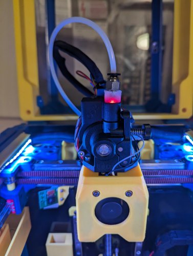
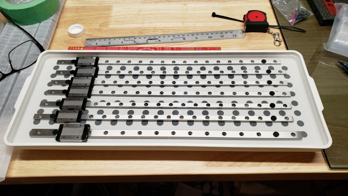
Hi All, I was encouraged to do a build diary but straight off the bat I am not a document type guy lol . Long story short I was off work for the Christmas holiday period and somehow ended up getting drawn into the Voron world. After watching a few too many youtube videos I decided to jump in at the deep end and started placing orders. Did not opt for a full kit as I wanted some control over what went into the system if I was going to spend this much on yet another "hobby" The parts have started trickling in but due to the order they are arriving I think I may have to wait till its all here to see some real progress. This may end up being a slow build depending on some order delays and how much I can stretch a day. I could not help myself though and started the basic frame ensuring it is all square. Since the rails were also in that order I cleaned them up with 91% IA (what I had at this time) and greased them. I used a grease which was readily available and closely matched the spec for Mobilux EP2 but since I do not really know the consistency(fluidity?) of the Mobilux EP2 this one has the carriage sliding down from top in lets say 2-3 secs. I compared this to a rail I have from a system I tried to build a few years ago and had never cleaned. That carriage drops almost instantly if I flip it vertically. So my question would be with the new ones greased up what kind of movement am I aiming for? Instant drop like the old rail or a consistent slide down the rail? Thanks and hopefully I can keep this thread updated with my progress...will post some parts that have arrived.
-
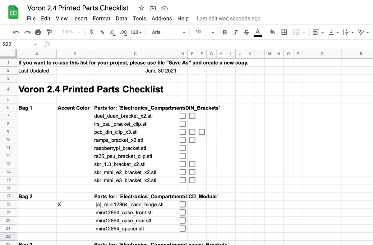
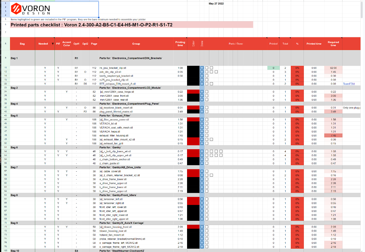
A Special thanks to user @WessPless for taking the time to update and share the latest version of the Printed parts list here. - Added parts for Clockwork2-StealthBurner and Printheads ( Revo_voron and Rapido ) https://docs.google.com/spreadsheets/d/114UsTTmAmNoVLu8TfBIWgCokO2Ns7ZT-J8wy7CQqhdE/edit?usp=sharing |I have found it incredibly useful to have a sheet to track my printed parts with the corresponding STL's In order to make this process easier for others I am sharing my list. I have a "zip-loc" bag for each folder in the official zip STLs folder, as I print them I update my checklist and add the printed part to the correct bag. https://docs.google.com/spreadsheets/d/1cG7ygisB7GtTDuSl7ssNVkVMdoOhT3Kb3uAJ8ahUwsg/edit?usp=sharing If you update the sheet to work better for you please share it with the community!
-
Version 2022.04.03
256 downloads
Important Notes Hello everyone, Here is my C920 camera mod, please follow the disassembly guide below to remove the current mount off the camera. Please keep the 4 bottom screws from the mount as you will need them for my mod. Instructions For Disassembly Found Here! This mod allows you to set 2 point position for your camera, BOM Qty Item 2 M3x40mm 1 M3x10mm 2 Nuts 1 M3 Hammerhead nut https://camo.githubusercontent.com/758a4b22a5c56662c568b7ffb24373659bc0266bcc721e882b16ef4f2bb51f16/68747470733a2f2f7777772e70617970616c6f626a656374732e636f6d2f656e5f55532f692f62746e2f62746e5f646f6e6174655f4c472e676966- 1 comment
-
- 4
-
-
- psychoshaft
- v1.8
- (and 2 more)
-
Version 2022.08.16
629 downloads
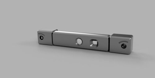
Tool free tensioner Name and specification Quantity SHCS M5x20 4 M4*0.7 Square nut 4 HHCS M4x16 4 D4x7x1(4x8x1)Flat washer 4 M5 Hex Nuts with Lock 4 bracket 2 tensioner 2 bracket image 2 tensioner image 2 wheel 4 PART PRINTING GUIDELINES MATERIAL ABS LAYER HEIGHT Recommended: 0.2mm EXTRUSION WIDTH Recommended: Forced 0.4mm INFILL TYPE Grid Gyroid Honeycomb Triangle Cubic SOLID TOP/BOTTOM LAYERS Recommended: 5 WALL COUNT Recommended: 4 INFILL PERCENTAGE Recommended: ≥60% -
Thought I may do a separate diary for those that wish to follow along.
-

Version 1.0.0
6,222 downloads
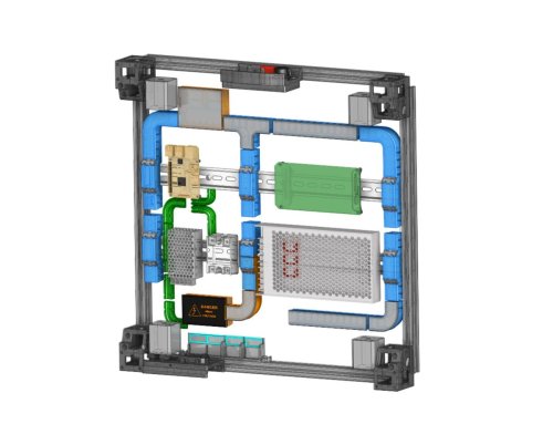
This Remix of RyanDam's Cable Management Duct for Voron Printers includes a number of custom ducts which I am using in my Voron 2.4 build. Thanks to the original author for the excellent design of the ducts, which this remix is based on! Since these models are designed to work with electrical components, if you use these models, it is at your own risk. Included here are several customized ducts which may help with cable management in a Voron build. I am still in the process of building mine, and I chose to use the same electronics layout as the voron spec. These ducts were designed based on my FYSETC R2.4 kit (which I am building as an R2.4 V2), so some dimensions may be different in other kits. This was designed with help from the STEP file from the Voron Github. There are several ducts included, which are designed to go over the DIN rails, and these parts include “BRIDGE” in their names. These parts will need to be printed with supports. There is an integrated support in the “HALF_BRIDGE” part, but that could also be printed with supports if needed. The “HALF_BRIDGE” part also has a thin raft like integrated support which will need to be removed. The 90 degree full bridge ducts are slightly different between the right hand (RH) and left hand (LH) versions. The difference is that the RH version (Cable_Management_Duct_Remix_DUCT-FULL-BRIDGE_90DEG_RH_5B.stl) is cut off a bit short to allow the power supply stabilization bracket to pass. I set my ducts up so that the high voltage AC wires, and the low voltage DC wires, would stay in separate ducts. To do this, I used two half ducts (one for the AC, and one for DC), on the center duct which crosses the lower DIN rail in the pics, which is nearest the power supply. I also printed the AC ducts in orange so they would be distinctive as a reminder they contain the high voltage AC wires. There are also plain and logo versions of the covers. The covers for the “BRIDGE” parts have print in place hinges, so if you find they are welded together when printed, it will be helpful to calibrate flow and horizontal expansion, as well as adjust the temps for the filament used. I made some minor improvements to parts since I printed mine (either for length or printability), but I do not think there will be any issues due to the changes. I printed the ducts for my printer in ABS and PETG, but use your best judgement on the appropriate material to use. I used VHB tape to secure them, but just note that once placed, they won't likely be going anywhere soon. Parts are not oriented for printing. Feedback is welcome, and if there is a problem I will try to fix it as I have time. I'm still building my printer, so if I run into an issue with this design, I will update it further, however I don't foresee any interference issues currently. Most likely I will not be able to accommodate requests to customize these further. The STEP files can be found on Printables (since the file was too large for this site), so remixing will be simpler. If you print these, or use these, it is at your own risk. I posted some remix covers for the boxes, which have inset printed labels, as well as some single and double wire guides which I am using to secure my ground wires. If you find these models useful, please post a like or a comment with some pics of your prints. You can find some other things I am working on at my blog (https://www.mystoopidstuff.com/blog), thanks for looking! You can find some additional low profile wire guides here: https://www.printables.com/model/502345-wire-management-guides There is a remix of the small box (not included here but shown in the pics), which holds two WAGO 221-415 connectors here: https://www.printables.com/model/505826-wago-box-for-the-remix-of-ryandams-cable-managemen The AC caution covers, with inset text and warning symbols for the small box and half bridge duct, can can be found here: https://www.printables.com/model/505838-ac-caution-covers-for-remix-of-ryandams-cable-mana/files- 1 comment
-
- 17
-
-
- cable management
- wire management
- (and 3 more)
-
Version 2022.05.03
384 downloads
Stealthburner Clockwork1 PCB Cover I designed a cover for users who are still rocking the CW1 with Stealthburner, with the same low-poly esthetic of stealthburner. This cover is a snug fit, so please make sure your wiring is all nice and tidy or you could have some issues.- 6 comments
-
- 17
-
-
-
Version 2022.08.30
396 downloads
Stealthburner (RC1) Crazy Dragon Fan Duct With special thanks to @chestwood96, sponsored by @3dmellow for the Crazy heatblock, as well as the awesome base design from the VoronDesign team, I'm able to create the Stealthburner Crazy Dragon fan duct. The fan duct is designed based on the Rapido toolhead mount (RC1), retro-fitted with Dragon styled duct allowing wind to blow towards the throat only. The duct is designed to be able to mount the Phaetus/Triangle Lab dragon heatsink with Mellow Crazy Heatblock (verified by myself and @chestwood96) Phaetus Dragon UHF mini (standard UHF version without the melt zone extender) TriangleLab T Volcano (to be verified) Print Parameters Print in standard Voron settings. Previews -
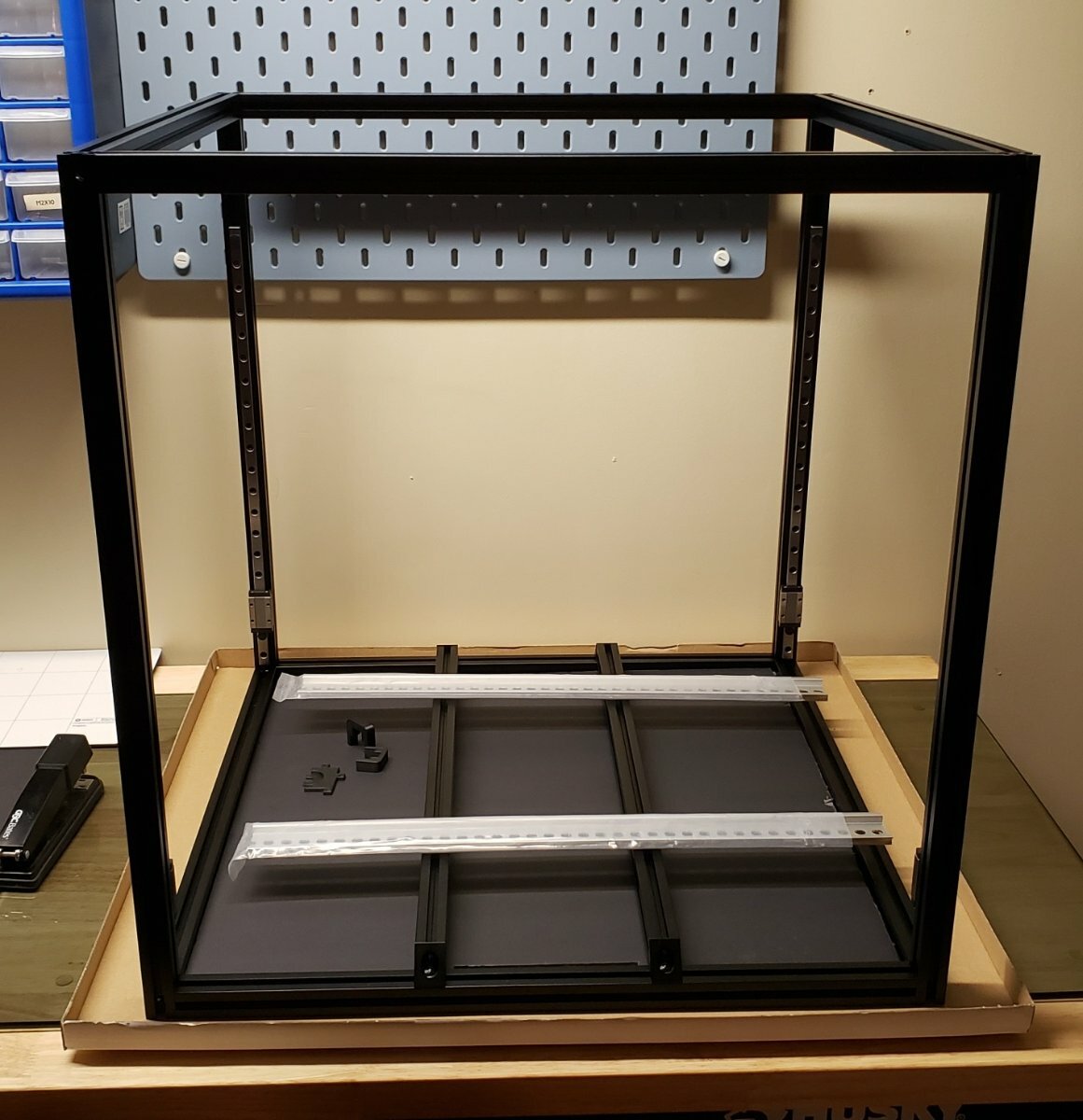
Hello all, As suggested to me in my intro thread I guess I will start this one as a place to document my Voron 2.4 build. I have had a Voxelab Aquila for the last couple years and have modded and worked that poor thing into the ground and have decided that I enjoy this hobby enough to make a big upgrade. Here is what I am planning and where I am as of today: Voron 2.4 350x350 direct drive CW2, E3D Revo all sourced parts with some smaller kits thrown in where it makes sense. I have a LDO frame kit in space grey on the way from KB-3D, along with a Tensor hardware kit. ACM deck, back and top panels coming from print solid. I ordered my 440C sus linear rails from Robotdig and Din 3 rail from Digikey. I attempted to start printing the ABS parts on my printer but its been problematic at best so I went ahead and ordered the functional parts from 3D pros Etsy shop in black and grey. I think that about covers it for now and figure this should get me started. I will update with pics after I get the first round of parts in and get started. Tim
-
Version 1.0.0
283 downloads
Allows you to use 2040 vertical posts instead of 2020 for the Trident. I also have this for the 2.4 but these work for the Trident.