Search the Community
Showing results for tags 'can'.
Found 3 results
-
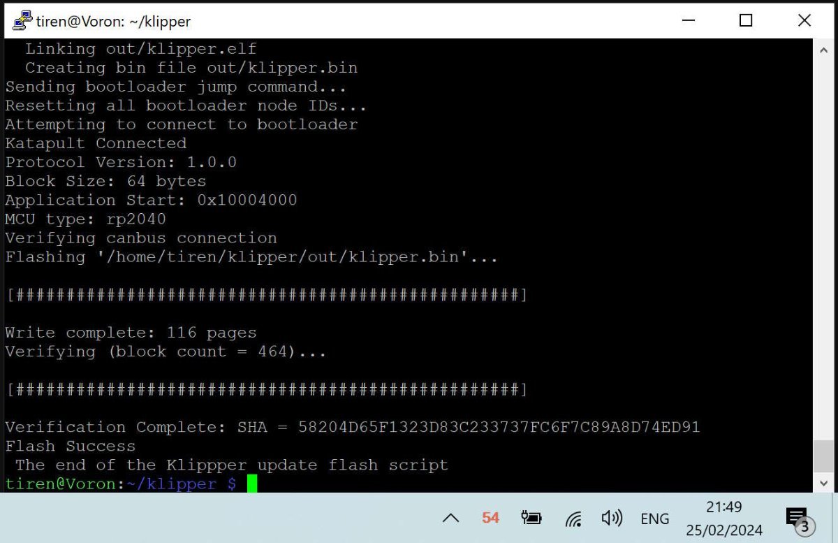
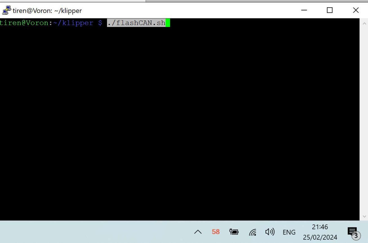
I have been converting my Voron 2.4 from many-cables-to-the-toolhead, into a single can-cable (4 wires) system. Even though I saw here that many people really did not like the CAN bus on their printers, mainly because it was new and unknown. The problem of the web is and always has been, that you never hear the 'satisfied' people. Only the very unhappy, the very happy and the sales-people. I hope this script will make it easier for some to make the step to the 'new'. I have never been afraid of new things. The problem was finding a way to find the set up I needed. From one came the other and what happened was, that I was able to combine information from a few sites / github pages I visited, and was able to write a simple script that did all the work. Actually very much like every software / game in the pre-windows 95 era, came with its own 'set-up' disk, with config.bat / setup.bat files. As long as I do not have a Klipper '95, I think this script will do for me. I tested it, and it takes 3 to 4 minutes to update the mainboard and toolhead PCB. Faster than 5 minutes I heard mentioned before. I will paste the script down here, with all the comments and the instructions. and attach as an attachment also. If there is a better way, let me know. It is information gathered mainly from Esoterical's guide. You will need information from this guide to set up your own script. -------------------------------- SCRIPT flashCAN.sh ------------------------------------------------------------------ #!/bin/bash ### without the extensive documentation and work of Esoterical, this would never have been possible. ### Besides Esoterical, this script builds standing on shoulders of: ### Eddie the engineer. https://www.youtube.com/watch?v=1P4UrJxChL8 Thanks! ### cruiten https://github.com/cruiten/Voron-Related/blob/main/CANbus/Documentation/SB2040_CAN/flash_klipper_script.md Thanks! ### uses # https://docs.kernel.org/kbuild/kconfig.html KCONFIG_CONFIG is used to define an alternative config file... ### to define a separate config file for mainboard (eg Octopus) or for a canbus toolhead PCB. For both cases one for katapult and one for klipper. ### the make menuconfig commands use the Esoterical github provided 'mainboard/common_hardware and toolhead_flashing/common_hardware maps provided image options ### https://canbus.esoterical.online/mainboard_flashing/common_hardware.html ### https://canbus.esoterical.online/toolhead_flashing/common_hardware.html ### HOW TO USE: Follow Esotericals guide, starting at the begin: https://canbus.esoterical.online/Getting_Started.html ### it will lead you through setting up a can network on your Klipper running os. ### I skipped the part about dedicated can_boards, and continued with the klipper USB 2 CAN bridge provided by my mainboard: https://canbus.esoterical.online/mainboard_flashing ### will go through flashing your mainboard for CAN. go through EVERY step. and DO NOT skip the STOP warnings. This will install katapult. USB2CANbus bridge ### afterwards it will assist you through flashing your toolhead: https://canbus.esoterical.online/toolhead_flashing ### like with the mainboard, you will install katapult and then the klipper can interface on it. ### when you are finished, you get advise on how to finish it: https://canbus.esoterical.online/Final_Steps.html ## You are happy and you see an update from Klipper in mainsail. You push the update button and your whole system is unaccessable, ## because your hardware is no more up to date with the latest klipper... ## in that case you can follow the "so you clicked the update button???" : https://canbus.esoterical.online/Updating.html ## because I did not want to go through the same repetitive steps, I made this below script. ## If I did not think this would be faster than the 5 minute update teamfdm.com @mvdveer needs to update his printers, I would have kept it to myself. ## -------------------------------------------------------- HOW TO USE ----------------------------------------------------------- ## save this document and copy to your klipper system into the /klipper directory. ## give it a name (eg. flashCAN.sh) ## ssh into your system. go to your klipper directory and run the command: sudo chmod +x flashCAN.sh ## now you can run the script by typing the following command in ssh ## ~/klipper/flashCAN.sh ## make sure to fill in your OWN values for ## - usb-katapult_your_mainboard_usb_id ## - yourmainboarduuid ## - yourtoolheaduuid # these are values for me! # yourmainboardUUID=403544310df5 # katapult_your_mainboard_usb_id = usb-katapult_stm32f446xx_200035000851313133353932-if00 # yourtoolheaduuid =21c36fa97c26 ## while installing CAN the first time, note your usb-katapult-mainboard-usb-id, mainboard UUID, toolhead UUID. ## or if you have a functioning CAN network, run ~/klippy-env/bin/python ~/klipper/scripts/canbus_query.py can0 to see a list of installed CAN devices. ## the UUID for mainboard and toolhead you need to put in your printer.cfg file, so you can retrieve it from there. ## But the USB serial ID you have to obtain after you put the mainboard into katapult boot flash mode (STEP 2 A below). ## after the command python3 ~/katapult/scripts/flashtool.py -i can0 -u yourmainboarduuid -r ## you will need to type: "ls /dev/serial/by-id" and it will give you your USB serial ID. ## once you have run through this script, comment out (put a # in front of the line) the line which has the "make menuconfig" in it. ## and the next time you have a klipper update that breaks your CAN, all you have to do, is to run this script once. #-------------------------------------FINAL WORDS-------------------------------------------------- # this script is for me and my set up. # HARDWARE # Raspberry Pi 4B, 8mb # Voron 2.4, 350 # Octopus Pro mainboard # SB2209 (RP2040) Big Tree Tech 2 part Toolhead PCB # Cartographer 3D Eddy Probe in CAN mode # with built in accelerometer / resonance tester # The Octopus functions as a CAN bridge. Cartographer 3D is connected to The SB2209 (RP2040). # The CAN bus is terminated at the Cartographer 3D probe. # SOFTWARE: # OS: Raspbian GNU/Linux 11 (bullseye) # Distro: MainsailOS 1.2.1 (bullseye) # klipper: v0.12.0-114-ga77d0790 # if you are not using this script on my system then anything can happen which I am not responsible for. echo "STEP 1 - UPDATE KATAPULT FROM GIT if needed" test -e ~/katapult && (cd ~/katapult && git pull) || (cd ~ && git clone https://github.com/Arksine/katapult) ; cd ~ echo "STEP 2a - FLASH MAINBOARD KATAPULT so we can flash it easily" cd ~/katapult make clean KCONFIG_CONFIG=config.mainboardKatapult # cleans old files make menuconfig KCONFIG_CONFIG=config.mainboardKatapult # this can be commented out for automation AFTER you have filled out correct fields for your card. or leave it in to have some control make KCONFIG_CONFIG=config.mainboardKatapult # this creates a deploy.bin python3 ~/katapult/scripts/flashtool.py -i can0 -u yourmainboarduuid -r # puts mainboard in katapult flash mode python3 ~/katapult/scripts/flashtool.py -f ~/katapult/out/deployer.bin -d /dev/serial/by-id/usb-katapult_your_mainboard_usb_id # flashes katapult to mainboard echo "STEP 2b - FLASH MAINBOARD so it works as a CAN BRIDGE, over KATAPULT" cd ~/klipper make clean KCONFIG_CONFIG=config.mainboardUSB2CANbb # cleans old files make menuconfig KCONFIG_CONFIG=config.mainboardUSB2CANbb # configuration for klipper-U2CBB. comment this line for automation make KCONFIG_CONFIG=config.mainboardUSB2CANbb # this creates klipper.bin sudo service klipper stop # mainboard still in katapult forced flash mode. so feel free to flash klipper can bridge on it! python3 ~/katapult/scripts/flashtool.py -f ~/klipper/out/klipper.bin -d /dev/serial/by-id/usb-katapult_yourmainboardusbid # flashes klipper-U2CBB to MAINBOARD sudo service klipper start echo "STEP 3a UPDATE TOOLHEAD KATAPULT so we can flash it easily" cd ~/katapult make clean KCONFIG_CONFIG=config.toolheadKatapult # clean old files make menuconfig KCONFIG_CONFIG=config.toolheadKatapult # comment out for full automation after once filled out! make KCONFIG_CONFIG=config.toolheadKatapult # build katapult deployer.bin python3 ~/katapult/scripts/flashtool.py -i can0 -u yourtoolheaduuid -r # put toolhead board into katapult flash mode python3 ~/katapult/scripts/flashtool.py -i can0 -u yourtoolheaduuid -f ~/katapult/out/deployer.bin # flash the katapult binary echo "STEP 3b UPDATING TOOLHEAD KLIPPER over KATAPULT" cd ~/klipper make clean KCONFIG_CONFIG=config.toolheadKlipper make menuconfig KCONFIG_CONFIG=config.toolheadKlipper make KCONFIG_CONFIG=config.toolheadKlipper sudo service klipper stop python3 ~/katapult/scripts/flashtool.py -i can0 -u yourtoolheaduuid -f ~/klipper/out/klipper.bin sudo service klipper start echo " The Klippper update flash script has finished. Hopefully all is working again :-)" flashCAN.sh

-
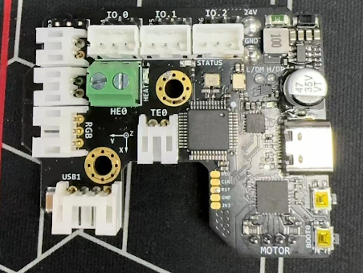
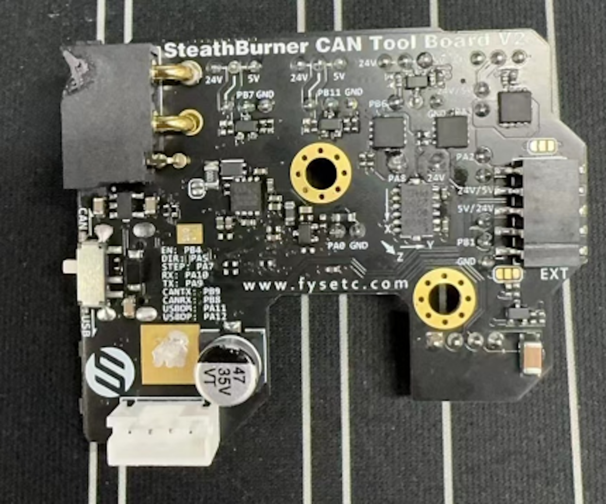
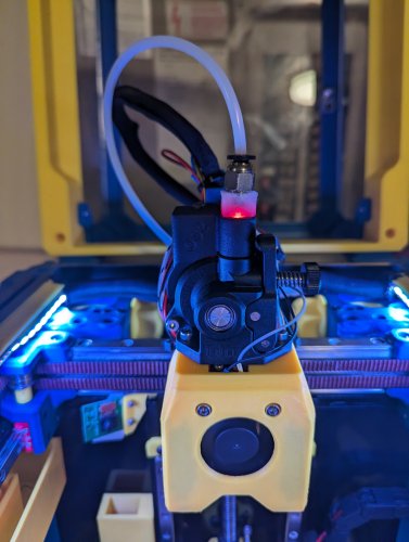
 I was amazed to set eyes on this board from Fysetc. It seems to be an early beta version of a toolhead PCB which can be switched to and from USB to CAN.
-

Version 1.0.0
205 downloads
CatPaw is the ideal toolhead for Voron Zero series with Orbiter 2.0 Extruder. I developed this toolhead as I was unhappy with the existing options. The standard Voron Zero 0.2 toolhead does not provide as much cooling as I prefer, and certainly less than the StealthBurner toolhead. My design goals were also minimum loss of print volume and maximum compatibility with toolheads and options for probe and filament sensor. CATPAW: Uses Voron Zero 0.2 toolhead cartridges, so should work with all toolheads for voron Zero 0.2 (fan saver recommended) 2x 4010 Blowers, with StealthBurner duct layout for near arctic level part cooling (2x 4010 provides more air than StealthBurner toolhead) Almost no loss in print volume. X axis should be full width, loss off a millimeter or so on X if you print with your door closed. (Magnets on my door are strong enough, so the door closes again if the toolhead bumps into it, giving me the full 120x120 mm even when printing ABS Option to add the slideswipe Probe. I shortened the probe, but all other parts can be used from https://github.com/SaltyPaws/Voron_0.1and0.2mods/SlideSwipe or original repo (https://github.com/chestwood96/SlideSwipe) Option to add under extruder filament Sensor Carriages are provided for MGN7 and MGN9 X-axis rails. It is recommended to print the provided X carriage for the appropriate rail. In order to minimize toolhead height, I lowered the screw hole for the rear mounting screw. The CATPAW toolhead will work with the stock Voron Zero 0.2 Carriage, but the screw securing the X-carriage from the rear will not fit. https://github.com/SaltyPaws/CATPAW_toolhead/raw/main/images/PXL_20240101_224037977.jpg?raw=true BOM 2x SHCS (preferred) or BHSC M3x25 bolt 3x M3 nut 2x NeoPixel 1x 3010 hotend fan 2x 4010 Blower 6x3mm magnets for probe (optional) 6mm steel ball for filament sensor (optional) Omron D2F-L micro-switch with lever for filament sensor (optional) 2x M2x12 or self-tapping screw to secure micro-switch (optional) Installation Instructions Assembly should be done in the following order: Probe Solder wires to 6x3mm magnets. In order to prevent loss of magnetism, let the magnets cool against another 6x3 magnet. Press the magnets into the slots by pushing the toolhead down on a hard object. Use a large flat soldering tip at around 230C to push the magnets deeper into the slots, you want the magnets to stick out ~0.5 to 1 mm. Again, let the magnets cool down attached to other magnets to prevent loss of magnetism. Ensure wire to magnet path has very low resistance (less than 4 ohm). route wires out trough little side window. Seal hole with red gasket maker. NeoPixels Create a chain of 2 neopixels. You do not have a lot of space to hide excess cable, so make the wires between the neopixels as short as possible, while still allowing them to slide into the slots. Test the neopixels! It will be more rework to remove the hotend fan and part cooling fans later. Fans First install 3010 part cooling fan. Be very careful to only press the edges of the fan, the fan will break when pushing the center of the fan (ask me how I know...) Then proceed with installing the blower fans. Use a knife to cut the upper right hand side of the blower fan (looking back to front). This is required for routing the majority of the wires. I used superglue to keep the fan together as you will remove a fan closing latch. I accidentally cut int the fanbox, and sealed up the hole with red gasket maker. For details - see pictures below: https://github.com/SaltyPaws/CATPAW_toolhead/raw/main/images/PXL_20231225_175242278.jpg?raw=true https://github.com/SaltyPaws/CATPAW_toolhead/raw/main/images/PXL_20231225_175256608.jpg?raw=true https://github.com/SaltyPaws/CATPAW_toolhead/raw/main/images/PXL_20231225_175325632.jpg?raw=true Toolhead Cardridge Ensure the heater wires are installed pointing towards the right hand fan that has space for wire routing. Thermistor, probe and fan wires will fit on the other side (left hand side fan). Hold off on installing the zip-ties, these are best installed after the toolhead is installed on the carriage. Filament Sensor Solder wires to filament sensor (2 outer most legs). You may want to shorten the legs somewhat for an easier fit. Trim lever, so that lever does not extend past micro-switch body Install micro-switch and ball Test sensor Install Toolhead Carefully mount toolhead, ensuring that wires are not pinched, and belt is not rubbing on gantry. The bulk of the wires will go in the gap carved out on the right hand side fan, the other side will have sufficient space for probe and fan wires. Min Probe See installation instructions in orignal repo: https://github.com/chestwood96/SlideSwipe-
- 2
-

-
- orbiter 2.0
- orbiter
- (and 33 more)