Search the Community
Showing results for tags 'filament sensor'.
Found 4 results
-


Version 1.0.0
205 downloads
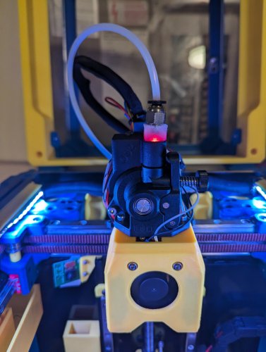
CatPaw is the ideal toolhead for Voron Zero series with Orbiter 2.0 Extruder. I developed this toolhead as I was unhappy with the existing options. The standard Voron Zero 0.2 toolhead does not provide as much cooling as I prefer, and certainly less than the StealthBurner toolhead. My design goals were also minimum loss of print volume and maximum compatibility with toolheads and options for probe and filament sensor. CATPAW: Uses Voron Zero 0.2 toolhead cartridges, so should work with all toolheads for voron Zero 0.2 (fan saver recommended) 2x 4010 Blowers, with StealthBurner duct layout for near arctic level part cooling (2x 4010 provides more air than StealthBurner toolhead) Almost no loss in print volume. X axis should be full width, loss off a millimeter or so on X if you print with your door closed. (Magnets on my door are strong enough, so the door closes again if the toolhead bumps into it, giving me the full 120x120 mm even when printing ABS Option to add the slideswipe Probe. I shortened the probe, but all other parts can be used from https://github.com/SaltyPaws/Voron_0.1and0.2mods/SlideSwipe or original repo (https://github.com/chestwood96/SlideSwipe) Option to add under extruder filament Sensor Carriages are provided for MGN7 and MGN9 X-axis rails. It is recommended to print the provided X carriage for the appropriate rail. In order to minimize toolhead height, I lowered the screw hole for the rear mounting screw. The CATPAW toolhead will work with the stock Voron Zero 0.2 Carriage, but the screw securing the X-carriage from the rear will not fit. https://github.com/SaltyPaws/CATPAW_toolhead/raw/main/images/PXL_20240101_224037977.jpg?raw=true BOM 2x SHCS (preferred) or BHSC M3x25 bolt 3x M3 nut 2x NeoPixel 1x 3010 hotend fan 2x 4010 Blower 6x3mm magnets for probe (optional) 6mm steel ball for filament sensor (optional) Omron D2F-L micro-switch with lever for filament sensor (optional) 2x M2x12 or self-tapping screw to secure micro-switch (optional) Installation Instructions Assembly should be done in the following order: Probe Solder wires to 6x3mm magnets. In order to prevent loss of magnetism, let the magnets cool against another 6x3 magnet. Press the magnets into the slots by pushing the toolhead down on a hard object. Use a large flat soldering tip at around 230C to push the magnets deeper into the slots, you want the magnets to stick out ~0.5 to 1 mm. Again, let the magnets cool down attached to other magnets to prevent loss of magnetism. Ensure wire to magnet path has very low resistance (less than 4 ohm). route wires out trough little side window. Seal hole with red gasket maker. NeoPixels Create a chain of 2 neopixels. You do not have a lot of space to hide excess cable, so make the wires between the neopixels as short as possible, while still allowing them to slide into the slots. Test the neopixels! It will be more rework to remove the hotend fan and part cooling fans later. Fans First install 3010 part cooling fan. Be very careful to only press the edges of the fan, the fan will break when pushing the center of the fan (ask me how I know...) Then proceed with installing the blower fans. Use a knife to cut the upper right hand side of the blower fan (looking back to front). This is required for routing the majority of the wires. I used superglue to keep the fan together as you will remove a fan closing latch. I accidentally cut int the fanbox, and sealed up the hole with red gasket maker. For details - see pictures below: https://github.com/SaltyPaws/CATPAW_toolhead/raw/main/images/PXL_20231225_175242278.jpg?raw=true https://github.com/SaltyPaws/CATPAW_toolhead/raw/main/images/PXL_20231225_175256608.jpg?raw=true https://github.com/SaltyPaws/CATPAW_toolhead/raw/main/images/PXL_20231225_175325632.jpg?raw=true Toolhead Cardridge Ensure the heater wires are installed pointing towards the right hand fan that has space for wire routing. Thermistor, probe and fan wires will fit on the other side (left hand side fan). Hold off on installing the zip-ties, these are best installed after the toolhead is installed on the carriage. Filament Sensor Solder wires to filament sensor (2 outer most legs). You may want to shorten the legs somewhat for an easier fit. Trim lever, so that lever does not extend past micro-switch body Install micro-switch and ball Test sensor Install Toolhead Carefully mount toolhead, ensuring that wires are not pinched, and belt is not rubbing on gantry. The bulk of the wires will go in the gap carved out on the right hand side fan, the other side will have sufficient space for probe and fan wires. Min Probe See installation instructions in orignal repo: https://github.com/chestwood96/SlideSwipe-
- 2
-

-
- orbiter 2.0
- orbiter
- (and 33 more)
-
Version 1.0.0
298 downloads
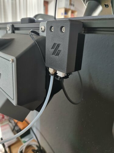
For my Voron I used a simple filament sensor. Since the simple ones that can be bought only have a sheet metal strip for scanning, there was always the problem after a runout that the filament wedged itself in the sensor when it was pushed back. So I made one that uses a roller actuated micro switch. The original is designed to mount to the back of a Voron that has a 3mm backplate and 3mm tape. In order to make it a little more universal, I have uploaded a version with a separate mounting distance, which you can simply use in the slicer in height. In addition to the printed parts you will need: 1 roller-actuated microswitch, e.g. Link 1 JST-XH, 2.54 male, e.g Link 1 Pushfit M10x1, e.g. Link 2 self-tapping screws M2x10 I printed the whole thing in ASA carbon, but in principle you can also use PLA, PETG or whatever - After printing, it is recommended to clean the filament hole with a 2mm drill so that the filament slides through nicely - It is advisable to fix the JST connector with a drop of superglue before soldering - I wired the switch as an "opener", if you need a closer then just use another pin. - After assembly, check whether the switch is actuated by the filament, if not you have to correct the roll bar a bit, I found that the switching points on the linked switches vary slightly -
Version 2021.08.09
17 downloads
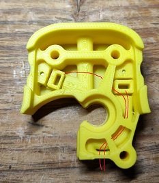
I wanted to create an invisible filament sensor inside the toolhead to check if the filament runs out or if there is a clog in the extruder gears. Tested on Dragon normal flow, not tested on Dragonfly, but it should work. https://github.com/diego589/Mini-AB-Filament-Sensor/raw/main/Images/Comparison.jpeg BOM For both (before and after the extruder's gears) 2x digital hall sensor, it doesn't matter if it's latching or not. I'm using U18 7x 4mm ball bearings 4x 5mm x 3mm Round Neodymium Magnets 2x 10k ohm resistor Thin wires, 32 AWG recommended BOM If you only want a sensor before the gears: 1x Digital hall sensor 1x ball bearing 2x Magnets 1x resistor Thin wires BOM If you only want a sensor after the gears: 1x Digital hall sensor 6x ball bearings 2x Magnets 1x resistor Thin wires Tools Multimeter Printed parts [a]FS_Mid_Body.stl - Needed Recommended to print 2 copies of every hall sensor holder [a]FS_Cowling_Dragon.stl - Not needed at all, but print it if you don't want to sand it down (step 13) Assembly Insert 6 balls in 1 Insert magnet in 1 Make sure that magnet is around 2mm down the tunnel, if not, then push it using filament or something similar Test your clearances by inserting filament, when there is no filament the magnet should be 2mm down the tunnel and when the filament is loaded, the magnet should raise up about 2mm Insert a magnet in 3, it should repel the magnet in 1. If you inserted it in the wrong orientation use an 1.5 or 2mm drill bit to remove it out of the hole Prepare hall sensor, solder resistor at no less than 10 cm from the sensor Test your circuit, move the hall sensor towards each magnets and check with a multimeter between GND and OUT, it should read 5v next to one and 0v next to the other Insert the hall sensor in [a]HallSensorHolder145-145.stl, then insert the holder with the sensor in 2 (small face of sensor pointing towards 3). DO NOT force it yet Load and unload filament and check with a multimeter if there is any variation, if the voltage doesn't change, rotate hall sensor and repeat If everything is working, push the hallsensor holder in place If it's not working, remove it and try with a different sensor holder, then repeat For the sensor that goes before the gears follow the same instructions but use just 1 ball bearing instead Bend the sensor pins until they are below the highlighted part (image below) Route your cable following the path as shown in the image below. If you didn't print [a]FS_Cowling_Dragon.stl you have to sand a path down yourself (black circle in image below) Choose any available pin on your board. In this case I am using RX2 and TX2 because they are right next to GND and +5v. See TestCode.txt-
- 4
-
-
- diego589
- filament sensor
- (and 2 more)
-
Version 1.0.0
152 downloads
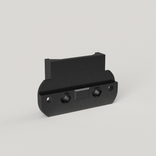
SLICER SETTINGS 4 Perimeters 40% Infill DISCLAIMER You are responsible for your own actions. CREDIT WHERE CREDIT IS DUE I am unsure of the original designer of this part. If you know, let me know. BILL OF MATERIAL 7g of Filament 2 M3x10mm SHCS for attaching the mount to the sensor 2 M3x6mm SHCS for attaching the mount to the frame 2 M3 T-nut