Search the Community
Showing results for tags 'tap'.
Found 13 results
-

Version 0.8
203 downloads
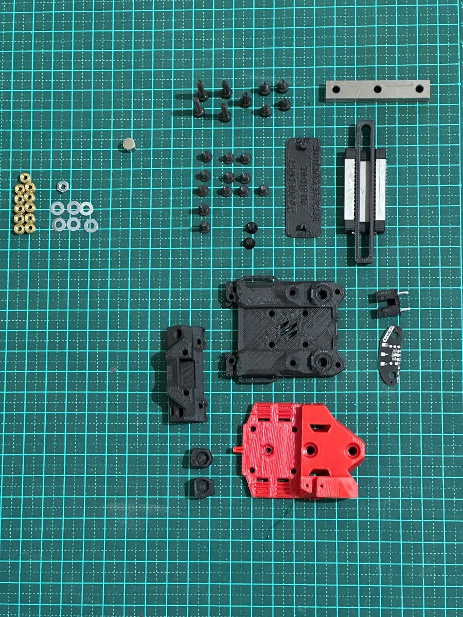
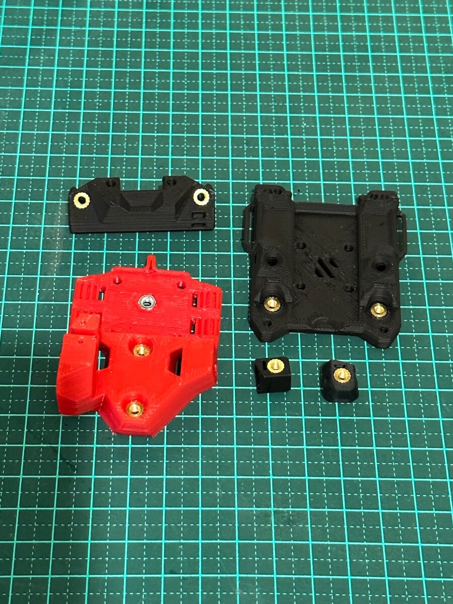
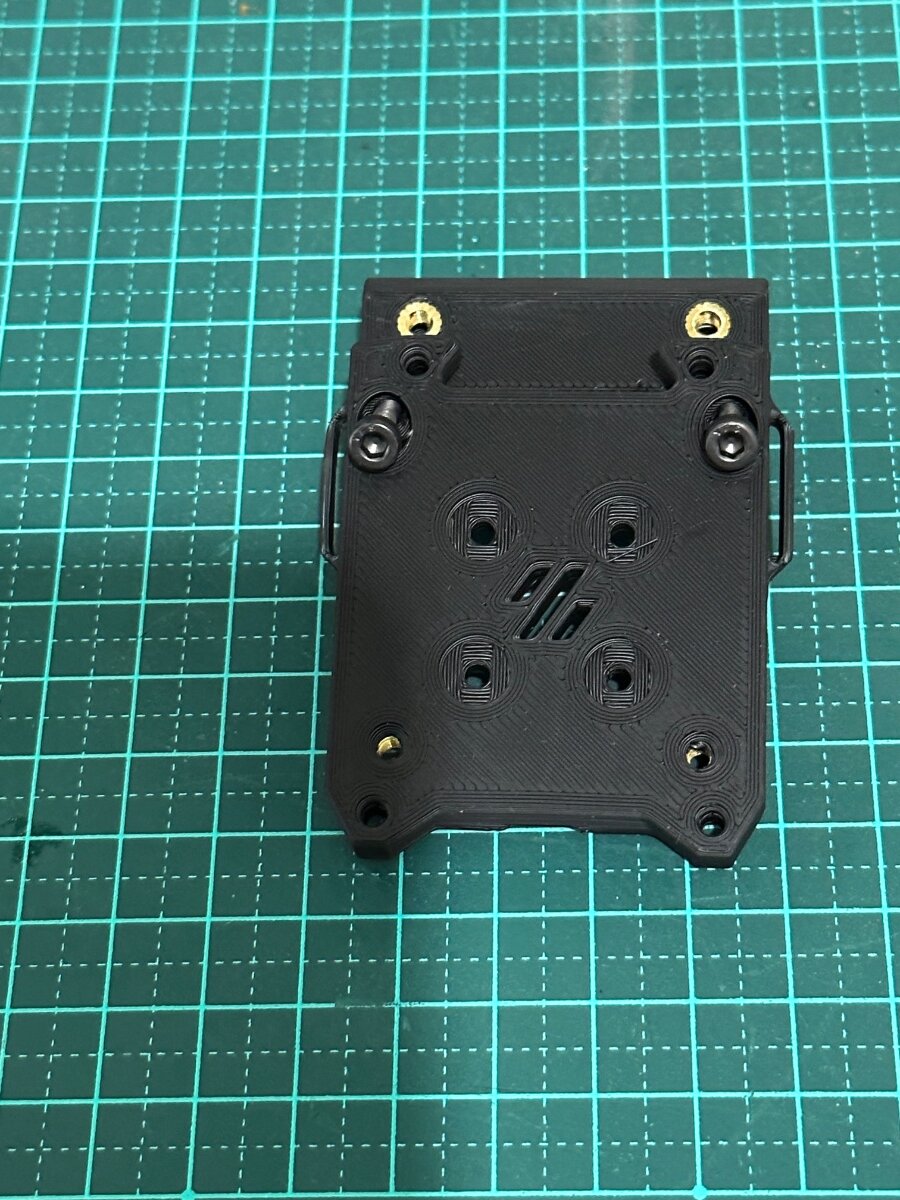
This is a flexure based nozzle probing option for mounting the Mini Stealth toolhead in a Voron Trident or V2.4. It uses a simple linear compliant mechanism to provide ~0.5mm of Z travel while being quite rigid in the other axes. It weighs around 20g fully assembled with Z and X endstops. It should require the same Print_Start preparations as the Voron TAP to ensure a clean nozzle and accurate probing. While probing with a scale on top of the bed, it applys about 600g of force. There are a few supports (shown in green) built in to make printing more reliable. After printing, the two inner sections will need to be gently, but firmly, pried apart from the two bridge sections while being careful not to plastically deform the flexures. There are four pockets for M3 square nuts to secure the Mini Stealth core piece using two M3x45 BHCS at the top and two M3x12 BHCS on the bottom. There are several different rear boss pieces depending on where you have your X endstop mounted. This piece is secured with a pair of M2x10 self tapping screws. Assembly: After ensuring that the flexure moves freely, install one of the grub screws in the top and screw it in just enough to remove the looseness in the flexure. This provides a known lower limit of travel. Install the Z_Stop_Boss with two M2 x 10 screws from the front. Install the Z micro-switch with the red trigger on the left (viewed from the back). The wires can be fed to the front through the lower gap in the flexure. Install the other M3 grub screw on the bottom of the DAB_Z_Boss. Screw it in until you hear the micro-switch trigger and then turn it back out until the trigger releases. This makes the trigger travel distance less than 0.5mm. Mount the x-carriage to the MGN12C carriage with four M3x12 BHCS. There is room to pull the four belt ends through and trim them at the front face of the DAB. Stealthburner Version: This version of DAB is a drop-in replacement for the Stealthburner x-frame pieces. It uses slightly different hardware than the official Stealthburner assembly, as shown in the picture below. Stealthburner on a Switchwire: This version of DAB fits a Stealthburner onto a Switchwire. It is printed in two parts and assembled with three M2x10 self tapping screws. Please leave comments, questions and feedback.- 18 comments
-
- 8
-

-
- voron
- stealthburner
- (and 4 more)
-

Voron TAP - New No probe mod from the Voron Design Team
mvdveer posted a topic in General Discussion
Thanks to @Meishu Started thread on suggestion of @RopusLongus. Thank you
-
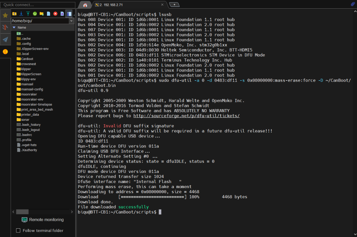
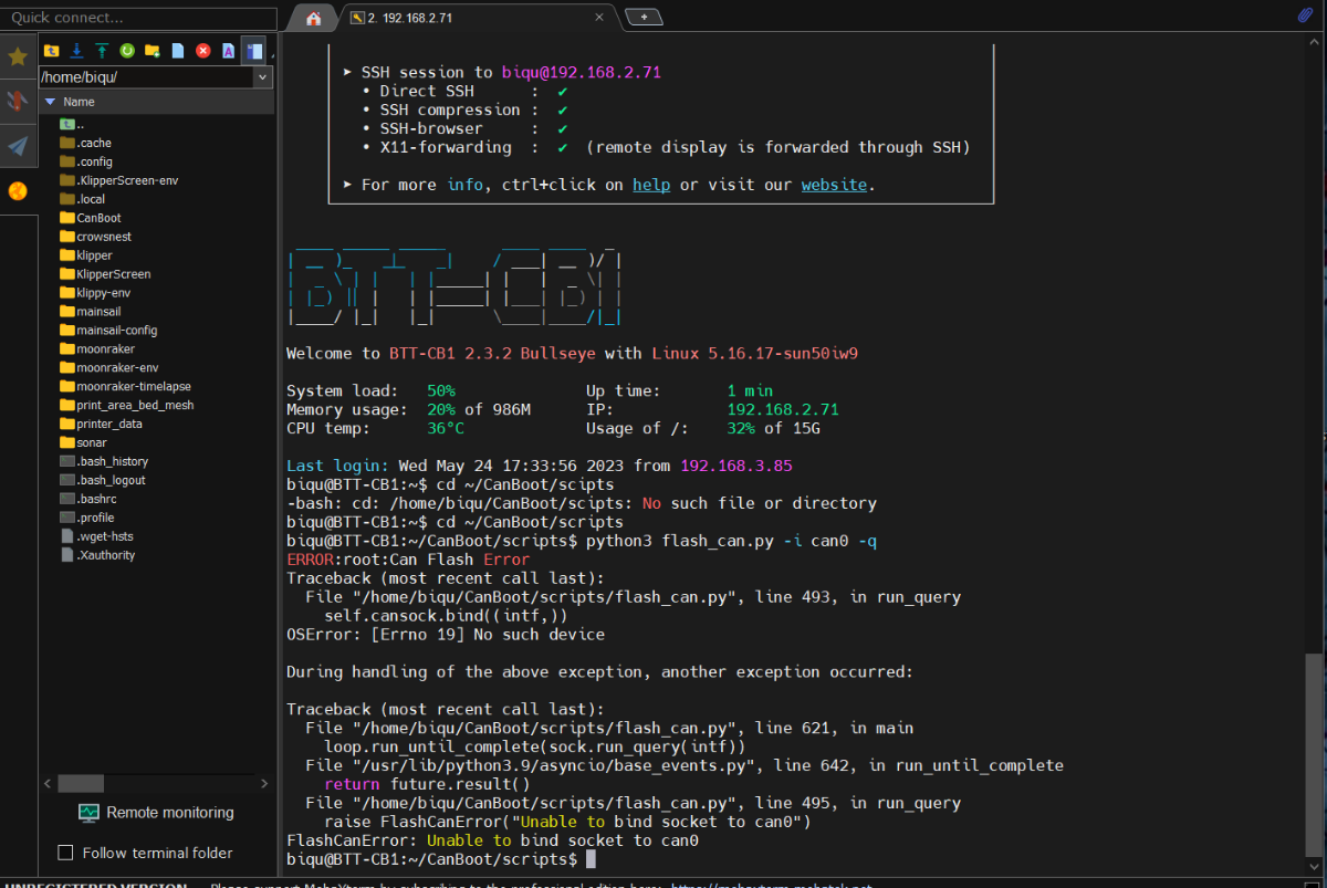
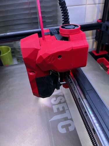
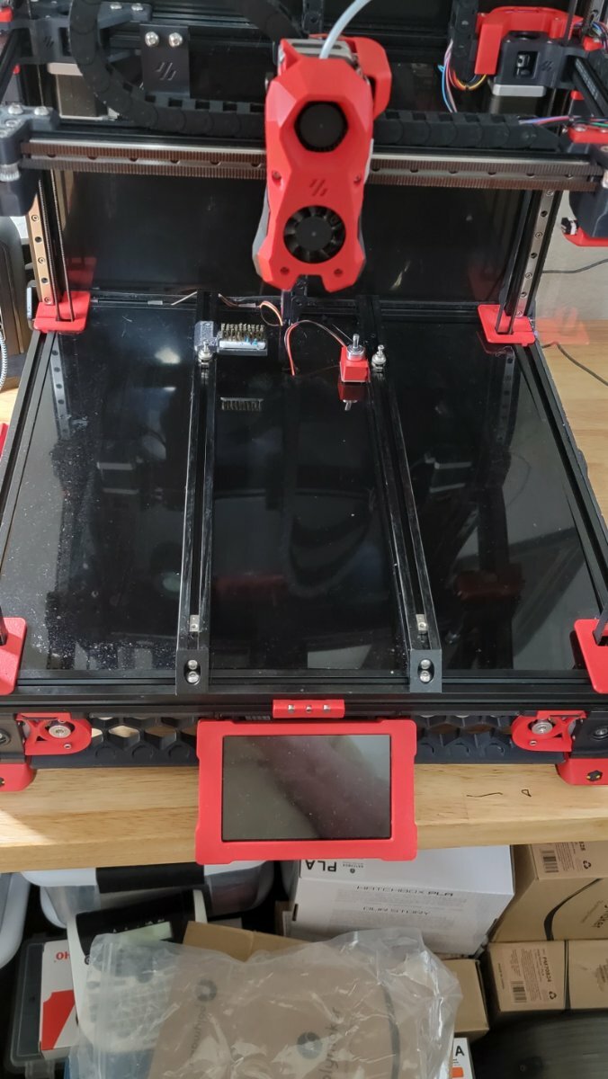
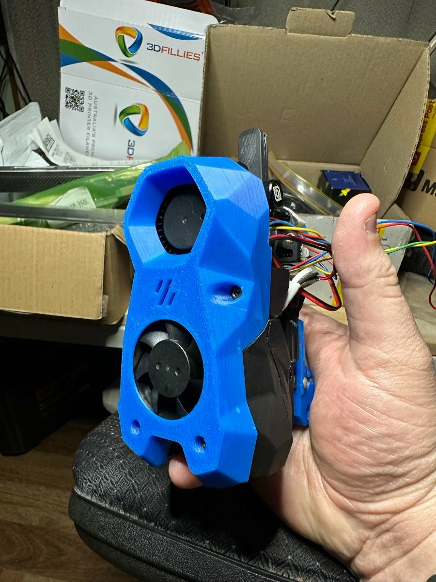
Sadly, this upgrade has been a night mare, everything that could go wrong has gone wrong. First, I realized that the CanBus board won't fit into the Steathbuners front piece, fine get the cutter out and modify the piece to make it fit.. can't print it now since I just ripped out all the cables. Installed the Rapido hot end in, the newly printed bottom pieces yay a win. Solder the pre crimped wire to the temp sensor. next redo all the chains, reroute all the other wire and the CanBus wire, rezip all the wires. The connector for the tap I cut the wrong end off, I'm like ok I will just re crimp it, oh look at of the 10 different JST connectors I have, I don't have this one. so, I have to magically hold in the wrong one and hope it makes a connection... Checking the toolhead for the Tap and its wobbling and the more I move the more it wobbles. I think my Chaotic Tap I got was a lemon, I didn't even get to print it was already wobbling from side to side the screws came loose for the Rail, I took it a part and retightened those screws and added lock tight. I put it all back together move the Tool head around Yay it seem to be better, aOh! I just realized the end stop won't work whit the chaotic tap, and realize I need to add a switch to the tool head body Great! Take it all apart again... sigh this feels like it the 4th time doing this... I get the switch in solder shrink tube wire and crimps, plug it.. screw it in and one of the screws instantly stripes sigh, rebuild the toolhead... Finally it was done on to flashing the board, everything seams good get through the first few parts all's good then I get to put the jumper on plug the cable in. cd ~/CanBoot/scripts python3 flash_can.py -i can0 -q and I can't seem to get past this part.. I can't move on because it won't give me the ID to flash the next part I gone over all the step like four times still can't get past this part... and I not sure what to do I have been working on this for the last few days, and I want to cry... Voron 2.4 Formbot kit, Manta MP8/CB1, BTT EB2209 Canbus, Chaoticlabs Tap, LGX Lite Extruder, Rapido Hotend, t...
-
Version 1.1.0
52 downloads
I wanted to use Tap instead of Klicky/euclid probe on my V2.4 but i only had CW1 with Stealthburner so i set about seeing if it was possible to modify CW1 to fit TAP as CW1 motor mount fixes from the rear which TAP can't do. I managed to find a solution so now this CW1 mod fixes from the front instead of the rear. The left side mounting screw now fixes the CW1 Extruder Motor Plate from the front with an M3x8 SHCS screw going through to the heatset in the Tap Upper as in Pic1, the same as designed for CW2. The right side screw now goes through the font of the CW1 Extruder Body with an M3x30 SHCH screw going through to the heatset in the Tap Upper as in Pic2, again the same as designed for CW2 Once the two parts of CW1 are mounted to the TAP then the Printhead Rear/Front can be mounted on the Tap as per Tap instructions for CW2 printhead mounting, the CW1 Extruder Body has access cut outs in the front for alen keys to be able to tighten those little screws that hold the printhead in place, the rest of the build is as per TAP SB fitting instructions. I have had this mod on my V2.4 with SB and CW1 for a couple of months now and it works great....-
- 6
-

-
-
- tap
- stealthburner
- (and 3 more)
-
Background... I'm a total beginner when it comes to configuration files because this is my first 3D printer build (other than a Prusa 2.5s that I "built"). I am going nuts trying to figure out a z_offset issue when trying to update Klipper. Here is what the ERROR states... (sorry, I was going to do a screenshot but can't figure out how to do that either in a Linux ecosystem). Option 'z_offset' in section 'probe' must be specified Once the underlying issue is corrected, use the "RESTART" command to reload the config and restart the host software. Printer is halted I followed the "Updating your Klipper config for Tap" instructions from Github BUT, I have no idea where or how the "PROBE_CALIBRATE" line is used. There are no values at the end of my config file because this error, and others that I have encountered, will not let the printer run. I have attached my config file, which probably has a bunch of errors in it. Build is Voron 2.4r with Phaetus Rapido and TAP as the only non standard mods from the Formbot kit. Help would be greatly appreciated. printer.cfg
-
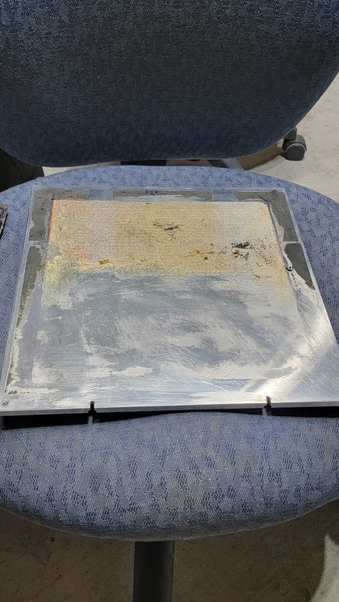
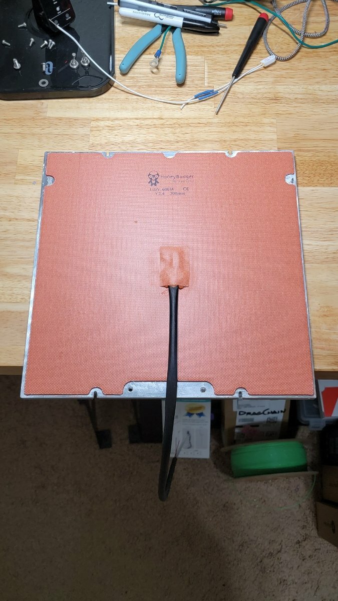
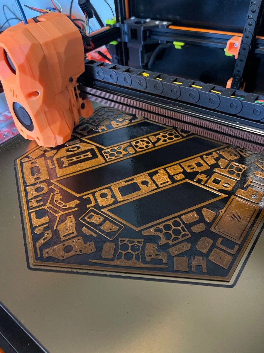
In order to keep the world spinning in the right direction and at a rotational rate of 15 degrees per hour... I have succumbed to the will of the masses and I'm installing a TAP on my Voron 2.4 300^3 so if the world goes to crap... It's not my fault! OK... All kidding aside, It was time I did a run thru and checked everything as well as installing a new bed heater. For those that don't know... The bed heater that came with my Formbot kit developed an issue with the thermistor where any temps over 70c created an erratic heating condition that would eventually end in an error stopping my print prematurely. I confirmed this by unplugging the bed heater thermistor and running a separate thermistor that I shoved under the heating pad. I used my printer that way for a good couple of months. So... First up. Remove the build plate, remove the old heater pad and clean off the old glue. I swear... there's got to be a Murphy's law that states: Adhesive always sticks to the part you want to reuse. Glue removal sucked. But then again... when is it ever easy LOL Needed to drill and tap a couple M5 holes for the ground and thermal fuse.
-

Tap Heat Dissipation - Just melted through hot end carrier
Todd posted a question in Voron 2 - Questions
So, I just finished building and installing Tap on my 2.4 build. Running a Phaetus Dragon HF hotend and no mods except for the Tap. Z-offset calibration was good (~.1mm) and a small test print came out great. Then I started a print with a calculated runtime of 11 hours. All went well for the first 20-minutes, but then I noticed my first layer seemed to be getting thinner and finally disappeared altogether. I immediately halted the print and raised the gantry and found the four screws securing the Dragon to the carrier had melted through the carrier and the hotend was literally dropping downward. I was printing PLA at the time and hotend temperature was stable at 210 degrees C. I believe the root cause may have been my hotend fan beginning to fail so I am replacing that. My question here is simple, has anyone else had issues with inadequate airflow through Tap and if so was it resolved successfully? -
So my V2.4R0 was build with PIF parts from Germany (Australia does not have a PIF supplier) The built was bases on a LDO frame and Magic Phoenix parts. The mistake I made was not to make sure I could purchase the filament used for the accent, so I plan to switch colour. Serial Request Link The current build has a ABBN and a SHT42 CANBus board, but is still using the cable chains. As of right now the CANBus power cable has a break at the XY join on the right, meaning the machine stops all the time. With the broken wire a friend printed the X Carriage parts below for me while I was getting my V0 up to scratch. While building the X Carriage below I put a bolt in which was too long causing the white spot in the image. I'll reprint this once the machine is running again. I plan to upgrade to a MGN12 X, a Stealthburner, GE5C Z Mount, Voron Tap, Rama's Front Idlers, Orbiter V2 (initially but switching to Vz-Hextrudort-Low Extruder) and a SHT36V2. I'm not sure about is the X rail, I have the original aluminium, 20x20 machined aluminium tube, a carbon 20x20 tube and X/Y backers but not sure what combo I should select. So as you can see, I have a number of decisions to make. I need to get these upgrades done ASAP, as I want to start building my Trident.
-
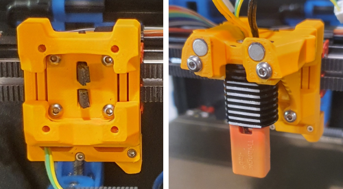
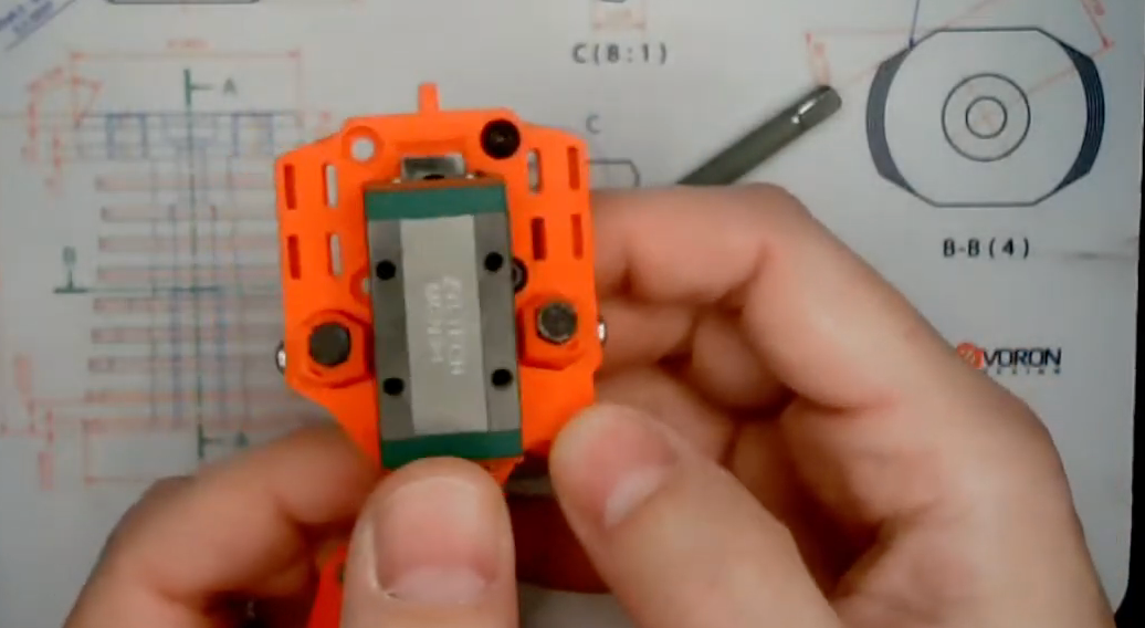
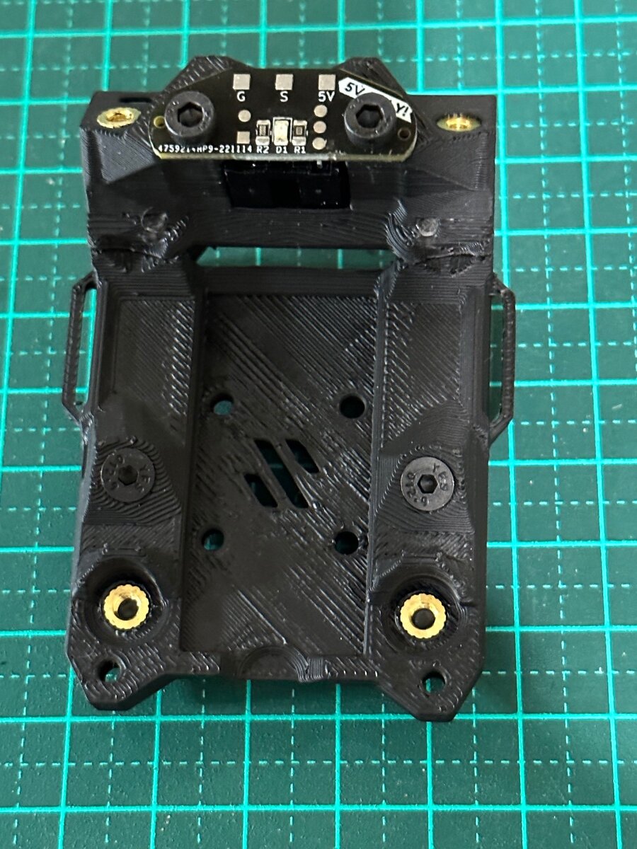
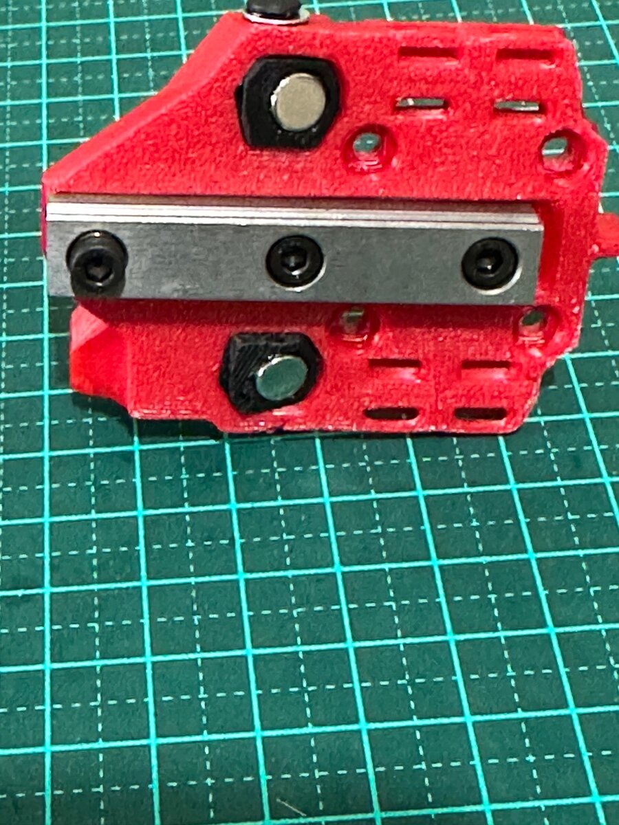
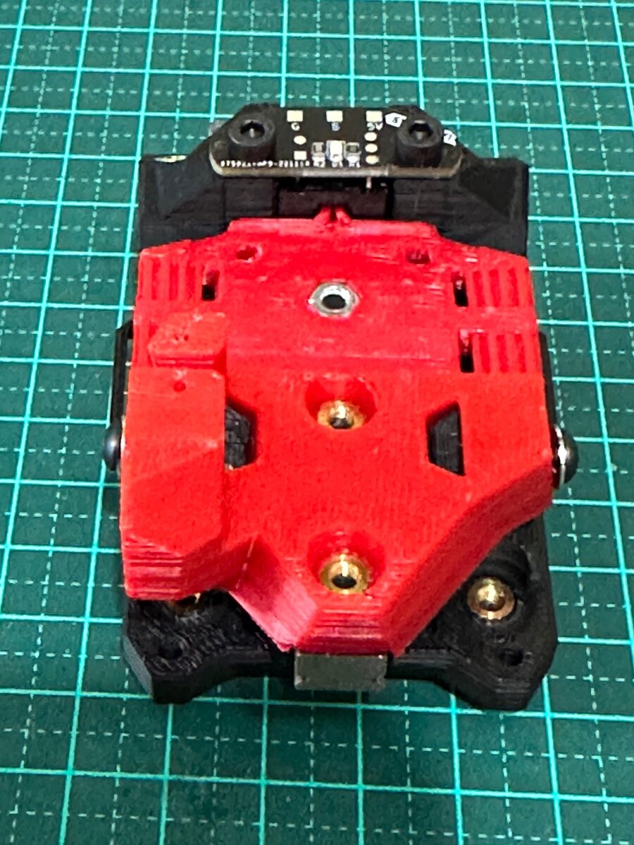
Finally got all the parts for the Voron Tap . Having read the manual twice and rewatched Steve's build - started the assembly: 1. Heatserts - 10 of them - nice and flush 2. Optical sensor with 5V PCB: 3. Magnets and Rail install: 4. Test Fit - Happy so far I'll finish here for now. Now to disassemble the toolhead on the Voron2.4 and fit the TAP
-
Version 2022.11.26
153 downloads
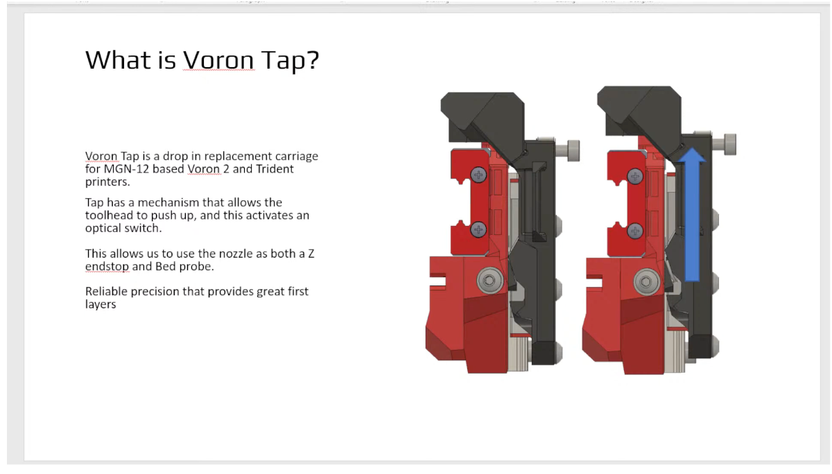
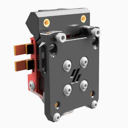
Tap is a nozzle-based z-probe for the V2 and Trident printer designs. The entire toolhead moves to trigger an optical switch. Tap offers many advantages over other z-probes; Tap is a drop in replacement for the X carriage which includes a nozzle probe mechanism. For Voron Trident and V2 printers -
I expected it already to be honest, and felt like it could have been me, but... still dont have all the parts, sooo.... I think the unklicky variant looks pretty ok too, no optic sensor/pcb needed, maybe be a big plus? Oops, sorry for placing this in the Diaries part itself, that was not my idea, can move it if needed...
-
Version 2022.11.26
1,356 downloads
Tap is a drop in replacement for the X carriage which includes a nozzle probe mechanism. For Voron Trident and V2 printers Bill of Materials Category Qty Description Notes Hardware 1 50 mm MGN9 Rail see cutting guide, Ends deburred, overall length +/- 1 mm Hardware 1 MGN-9H Carriage Medium preload (Z1) is preferred, but regular preload will work. Carriage must be removable from rail. Hardware 2 6 mm x 3 mm magnet 6 mm diameter, 3 mm tall cylinders. N52 strength preferred, N35 or higher strength required. Hardware 11 M3 Heatset Insert Standard Voron spec 4.7 mm diameter inserts Hardware 1 H3 Hex Nut ISO 4032 Hardware 6 M3 Washer DIN 125, 7mm outer diameter, 0.5 mm thickness Hardware 2 M3 x 20 SHCS Socket head cap screw Hardware 2 M3 x 16 SHCS Socket head cap screw Hardware 1 M3 x 12 SHCS Socket head cap screw Hardware 3 M3 x 8 SHCS Socket head cap screw Hardware 1 M3 x 6 SHCS Socket head cap screw Hardware 2 M3 x 6 FHCS Flat head cap screw. MUST BE MAGNETIC. No stainless, may be black oxide or zinc coated. Hardware 2 M3 x 10 BHCS Button Head Cap Screw Hardware 10 M3 x 6 BHCS Button Head Cap Screw Sensor Options: Select either “Wired Sensor” or “PCB Sensor" Wired Category Qty Description Notes Links Electronics 1 220 Ohm resistor ¼ Watt, +/- 10% tolerance resistor Electronics 1 OPB Wired Sensor Optek sensor, wired. OPB991 OPB991P51Z OPB991L51Z OPB991T51Z OPB991T11Z https://www.digikey.com/short/rrjtmvwm OPB991L11 https://www.digikey.com/short/cnnhjr5n PCB Sensor Category Qty Description Notes Links Electronics 1 OptoTap v2 PCB Electronics 1 OPB PCB Sensor Optek sensor: OPB666N or OPB971N51 OPB666N https://www.digikey.com/short/f2mzw5rm OPB971N51 https://www.digikey.com/short/m9rz73fp