Search the Community
Showing results for tags 'mini'.
Found 2 results
-

Version 0.8
203 downloads
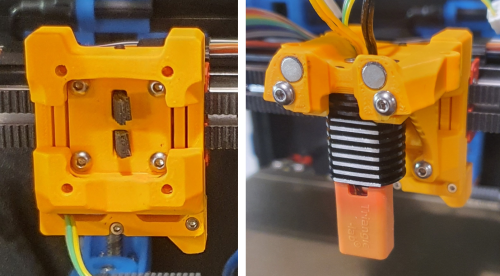
This is a flexure based nozzle probing option for mounting the Mini Stealth toolhead in a Voron Trident or V2.4. It uses a simple linear compliant mechanism to provide ~0.5mm of Z travel while being quite rigid in the other axes. It weighs around 20g fully assembled with Z and X endstops. It should require the same Print_Start preparations as the Voron TAP to ensure a clean nozzle and accurate probing. While probing with a scale on top of the bed, it applys about 600g of force. There are a few supports (shown in green) built in to make printing more reliable. After printing, the two inner sections will need to be gently, but firmly, pried apart from the two bridge sections while being careful not to plastically deform the flexures. There are four pockets for M3 square nuts to secure the Mini Stealth core piece using two M3x45 BHCS at the top and two M3x12 BHCS on the bottom. There are several different rear boss pieces depending on where you have your X endstop mounted. This piece is secured with a pair of M2x10 self tapping screws. Assembly: After ensuring that the flexure moves freely, install one of the grub screws in the top and screw it in just enough to remove the looseness in the flexure. This provides a known lower limit of travel. Install the Z_Stop_Boss with two M2 x 10 screws from the front. Install the Z micro-switch with the red trigger on the left (viewed from the back). The wires can be fed to the front through the lower gap in the flexure. Install the other M3 grub screw on the bottom of the DAB_Z_Boss. Screw it in until you hear the micro-switch trigger and then turn it back out until the trigger releases. This makes the trigger travel distance less than 0.5mm. Mount the x-carriage to the MGN12C carriage with four M3x12 BHCS. There is room to pull the four belt ends through and trim them at the front face of the DAB. Stealthburner Version: This version of DAB is a drop-in replacement for the Stealthburner x-frame pieces. It uses slightly different hardware than the official Stealthburner assembly, as shown in the picture below. Stealthburner on a Switchwire: This version of DAB fits a Stealthburner onto a Switchwire. It is printed in two parts and assembled with three M2x10 self tapping screws. Please leave comments, questions and feedback.- 18 comments
-
- 8
-

-
- voron
- stealthburner
- (and 4 more)
-

Version 1.0.0
205 downloads
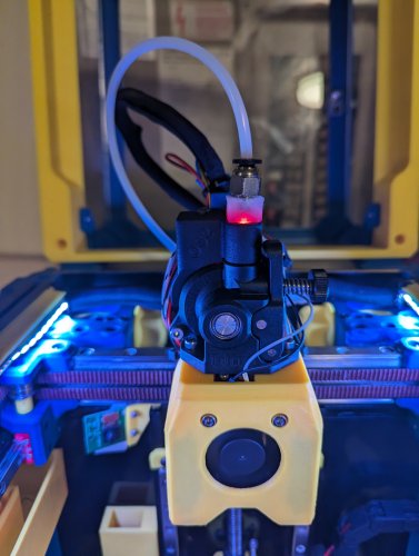
CatPaw is the ideal toolhead for Voron Zero series with Orbiter 2.0 Extruder. I developed this toolhead as I was unhappy with the existing options. The standard Voron Zero 0.2 toolhead does not provide as much cooling as I prefer, and certainly less than the StealthBurner toolhead. My design goals were also minimum loss of print volume and maximum compatibility with toolheads and options for probe and filament sensor. CATPAW: Uses Voron Zero 0.2 toolhead cartridges, so should work with all toolheads for voron Zero 0.2 (fan saver recommended) 2x 4010 Blowers, with StealthBurner duct layout for near arctic level part cooling (2x 4010 provides more air than StealthBurner toolhead) Almost no loss in print volume. X axis should be full width, loss off a millimeter or so on X if you print with your door closed. (Magnets on my door are strong enough, so the door closes again if the toolhead bumps into it, giving me the full 120x120 mm even when printing ABS Option to add the slideswipe Probe. I shortened the probe, but all other parts can be used from https://github.com/SaltyPaws/Voron_0.1and0.2mods/SlideSwipe or original repo (https://github.com/chestwood96/SlideSwipe) Option to add under extruder filament Sensor Carriages are provided for MGN7 and MGN9 X-axis rails. It is recommended to print the provided X carriage for the appropriate rail. In order to minimize toolhead height, I lowered the screw hole for the rear mounting screw. The CATPAW toolhead will work with the stock Voron Zero 0.2 Carriage, but the screw securing the X-carriage from the rear will not fit. https://github.com/SaltyPaws/CATPAW_toolhead/raw/main/images/PXL_20240101_224037977.jpg?raw=true BOM 2x SHCS (preferred) or BHSC M3x25 bolt 3x M3 nut 2x NeoPixel 1x 3010 hotend fan 2x 4010 Blower 6x3mm magnets for probe (optional) 6mm steel ball for filament sensor (optional) Omron D2F-L micro-switch with lever for filament sensor (optional) 2x M2x12 or self-tapping screw to secure micro-switch (optional) Installation Instructions Assembly should be done in the following order: Probe Solder wires to 6x3mm magnets. In order to prevent loss of magnetism, let the magnets cool against another 6x3 magnet. Press the magnets into the slots by pushing the toolhead down on a hard object. Use a large flat soldering tip at around 230C to push the magnets deeper into the slots, you want the magnets to stick out ~0.5 to 1 mm. Again, let the magnets cool down attached to other magnets to prevent loss of magnetism. Ensure wire to magnet path has very low resistance (less than 4 ohm). route wires out trough little side window. Seal hole with red gasket maker. NeoPixels Create a chain of 2 neopixels. You do not have a lot of space to hide excess cable, so make the wires between the neopixels as short as possible, while still allowing them to slide into the slots. Test the neopixels! It will be more rework to remove the hotend fan and part cooling fans later. Fans First install 3010 part cooling fan. Be very careful to only press the edges of the fan, the fan will break when pushing the center of the fan (ask me how I know...) Then proceed with installing the blower fans. Use a knife to cut the upper right hand side of the blower fan (looking back to front). This is required for routing the majority of the wires. I used superglue to keep the fan together as you will remove a fan closing latch. I accidentally cut int the fanbox, and sealed up the hole with red gasket maker. For details - see pictures below: https://github.com/SaltyPaws/CATPAW_toolhead/raw/main/images/PXL_20231225_175242278.jpg?raw=true https://github.com/SaltyPaws/CATPAW_toolhead/raw/main/images/PXL_20231225_175256608.jpg?raw=true https://github.com/SaltyPaws/CATPAW_toolhead/raw/main/images/PXL_20231225_175325632.jpg?raw=true Toolhead Cardridge Ensure the heater wires are installed pointing towards the right hand fan that has space for wire routing. Thermistor, probe and fan wires will fit on the other side (left hand side fan). Hold off on installing the zip-ties, these are best installed after the toolhead is installed on the carriage. Filament Sensor Solder wires to filament sensor (2 outer most legs). You may want to shorten the legs somewhat for an easier fit. Trim lever, so that lever does not extend past micro-switch body Install micro-switch and ball Test sensor Install Toolhead Carefully mount toolhead, ensuring that wires are not pinched, and belt is not rubbing on gantry. The bulk of the wires will go in the gap carved out on the right hand side fan, the other side will have sufficient space for probe and fan wires. Min Probe See installation instructions in orignal repo: https://github.com/chestwood96/SlideSwipe-
- 2
-
-
- orbiter 2.0
- orbiter
- (and 33 more)