Search the Community
Showing results for tags 'probe'.
Found 7 results
-
Klipper pushed a large update, which seems to be the BTT branch of Klipper that supports the BTT Eddy probe. This has as consequence that ALL probes that have a klipper plugin, like Beacon and Cartographer, have to follow the same routine that the BTT Eddy probe requires. This has as consequence that these probes did not function as soon as the update was applied. Luckily the programmers quickly reacted and within a few hours there was already an update from Beacon and Cartographer. HOWEVER, with such a huge update, which cost BTT almost a year to (have) develop(ed), issues still may arise. So do like I did, and wait a bit longer before updating... Do not fix something that works perfectly. And if you already did update, and you have a completely useless printer and are considering going back to TAP or Klicky, run this command in your SSH, which will reset all updates from github back to the time before the BTT-Klipper. cd ~/klipper git reset 6cd174208bd9bbd51dc0d519a26661fb926d038a --hard After this, a reboot (power recycle) may be necessary.

-

Version 1.0.0
205 downloads
CatPaw is the ideal toolhead for Voron Zero series with Orbiter 2.0 Extruder. I developed this toolhead as I was unhappy with the existing options. The standard Voron Zero 0.2 toolhead does not provide as much cooling as I prefer, and certainly less than the StealthBurner toolhead. My design goals were also minimum loss of print volume and maximum compatibility with toolheads and options for probe and filament sensor. CATPAW: Uses Voron Zero 0.2 toolhead cartridges, so should work with all toolheads for voron Zero 0.2 (fan saver recommended) 2x 4010 Blowers, with StealthBurner duct layout for near arctic level part cooling (2x 4010 provides more air than StealthBurner toolhead) Almost no loss in print volume. X axis should be full width, loss off a millimeter or so on X if you print with your door closed. (Magnets on my door are strong enough, so the door closes again if the toolhead bumps into it, giving me the full 120x120 mm even when printing ABS Option to add the slideswipe Probe. I shortened the probe, but all other parts can be used from https://github.com/SaltyPaws/Voron_0.1and0.2mods/SlideSwipe or original repo (https://github.com/chestwood96/SlideSwipe) Option to add under extruder filament Sensor Carriages are provided for MGN7 and MGN9 X-axis rails. It is recommended to print the provided X carriage for the appropriate rail. In order to minimize toolhead height, I lowered the screw hole for the rear mounting screw. The CATPAW toolhead will work with the stock Voron Zero 0.2 Carriage, but the screw securing the X-carriage from the rear will not fit. https://github.com/SaltyPaws/CATPAW_toolhead/raw/main/images/PXL_20240101_224037977.jpg?raw=true BOM 2x SHCS (preferred) or BHSC M3x25 bolt 3x M3 nut 2x NeoPixel 1x 3010 hotend fan 2x 4010 Blower 6x3mm magnets for probe (optional) 6mm steel ball for filament sensor (optional) Omron D2F-L micro-switch with lever for filament sensor (optional) 2x M2x12 or self-tapping screw to secure micro-switch (optional) Installation Instructions Assembly should be done in the following order: Probe Solder wires to 6x3mm magnets. In order to prevent loss of magnetism, let the magnets cool against another 6x3 magnet. Press the magnets into the slots by pushing the toolhead down on a hard object. Use a large flat soldering tip at around 230C to push the magnets deeper into the slots, you want the magnets to stick out ~0.5 to 1 mm. Again, let the magnets cool down attached to other magnets to prevent loss of magnetism. Ensure wire to magnet path has very low resistance (less than 4 ohm). route wires out trough little side window. Seal hole with red gasket maker. NeoPixels Create a chain of 2 neopixels. You do not have a lot of space to hide excess cable, so make the wires between the neopixels as short as possible, while still allowing them to slide into the slots. Test the neopixels! It will be more rework to remove the hotend fan and part cooling fans later. Fans First install 3010 part cooling fan. Be very careful to only press the edges of the fan, the fan will break when pushing the center of the fan (ask me how I know...) Then proceed with installing the blower fans. Use a knife to cut the upper right hand side of the blower fan (looking back to front). This is required for routing the majority of the wires. I used superglue to keep the fan together as you will remove a fan closing latch. I accidentally cut int the fanbox, and sealed up the hole with red gasket maker. For details - see pictures below: https://github.com/SaltyPaws/CATPAW_toolhead/raw/main/images/PXL_20231225_175242278.jpg?raw=true https://github.com/SaltyPaws/CATPAW_toolhead/raw/main/images/PXL_20231225_175256608.jpg?raw=true https://github.com/SaltyPaws/CATPAW_toolhead/raw/main/images/PXL_20231225_175325632.jpg?raw=true Toolhead Cardridge Ensure the heater wires are installed pointing towards the right hand fan that has space for wire routing. Thermistor, probe and fan wires will fit on the other side (left hand side fan). Hold off on installing the zip-ties, these are best installed after the toolhead is installed on the carriage. Filament Sensor Solder wires to filament sensor (2 outer most legs). You may want to shorten the legs somewhat for an easier fit. Trim lever, so that lever does not extend past micro-switch body Install micro-switch and ball Test sensor Install Toolhead Carefully mount toolhead, ensuring that wires are not pinched, and belt is not rubbing on gantry. The bulk of the wires will go in the gap carved out on the right hand side fan, the other side will have sufficient space for probe and fan wires. Min Probe See installation instructions in orignal repo: https://github.com/chestwood96/SlideSwipe-
- 2
-

-
- orbiter 2.0
- orbiter
- (and 33 more)
-

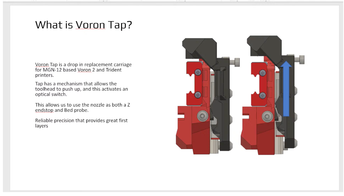
Voron TAP - New No probe mod from the Voron Design Team
mvdveer posted a topic in General Discussion
Thanks to @Meishu Started thread on suggestion of @RopusLongus. Thank you
-
Version 1.1.0
52 downloads
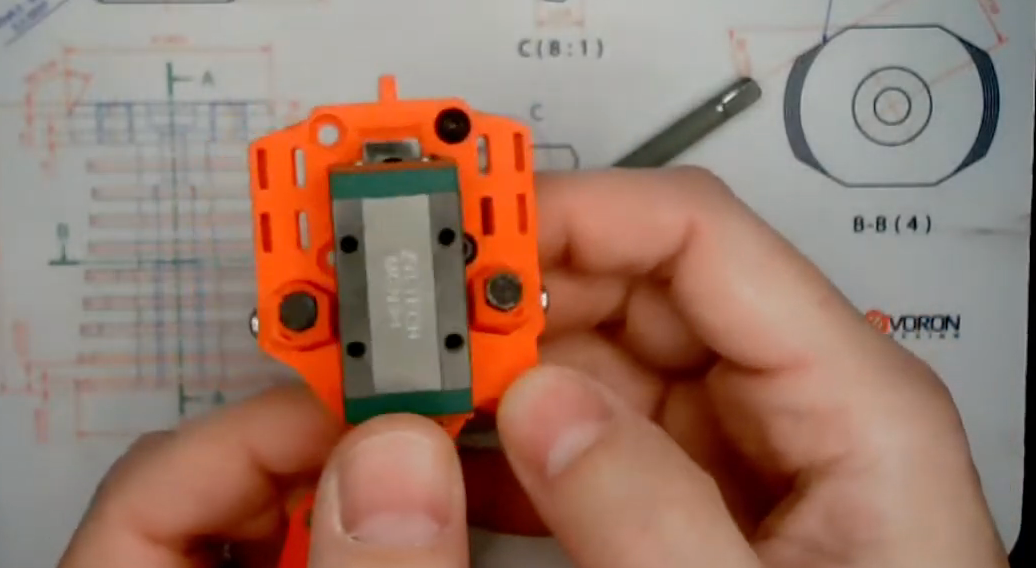
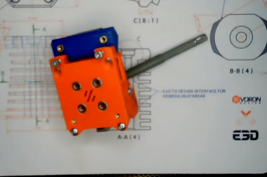
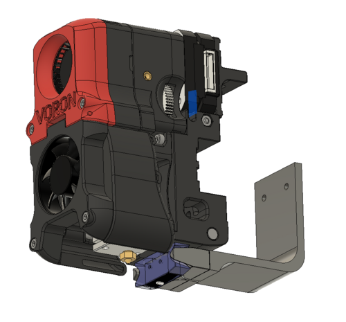
I wanted to use Tap instead of Klicky/euclid probe on my V2.4 but i only had CW1 with Stealthburner so i set about seeing if it was possible to modify CW1 to fit TAP as CW1 motor mount fixes from the rear which TAP can't do. I managed to find a solution so now this CW1 mod fixes from the front instead of the rear. The left side mounting screw now fixes the CW1 Extruder Motor Plate from the front with an M3x8 SHCS screw going through to the heatset in the Tap Upper as in Pic1, the same as designed for CW2. The right side screw now goes through the font of the CW1 Extruder Body with an M3x30 SHCH screw going through to the heatset in the Tap Upper as in Pic2, again the same as designed for CW2 Once the two parts of CW1 are mounted to the TAP then the Printhead Rear/Front can be mounted on the Tap as per Tap instructions for CW2 printhead mounting, the CW1 Extruder Body has access cut outs in the front for alen keys to be able to tighten those little screws that hold the printhead in place, the rest of the build is as per TAP SB fitting instructions. I have had this mod on my V2.4 with SB and CW1 for a couple of months now and it works great....-
- 6
-

-
-
- tap
- stealthburner
- (and 3 more)
-
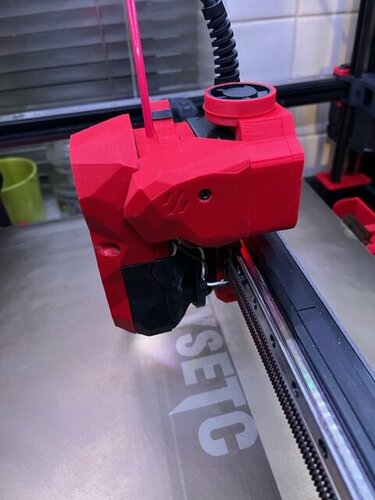
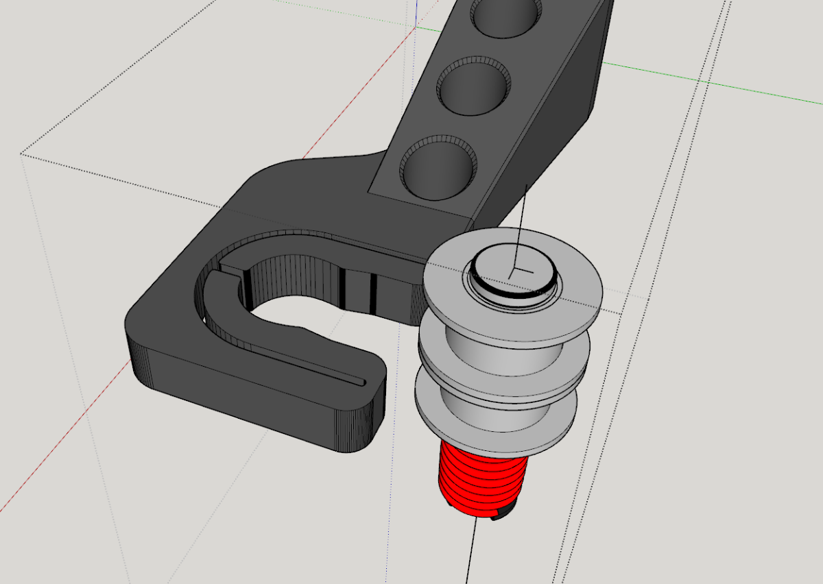
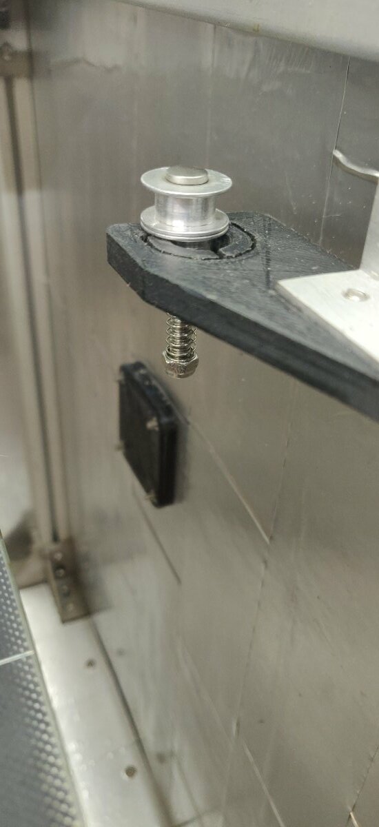
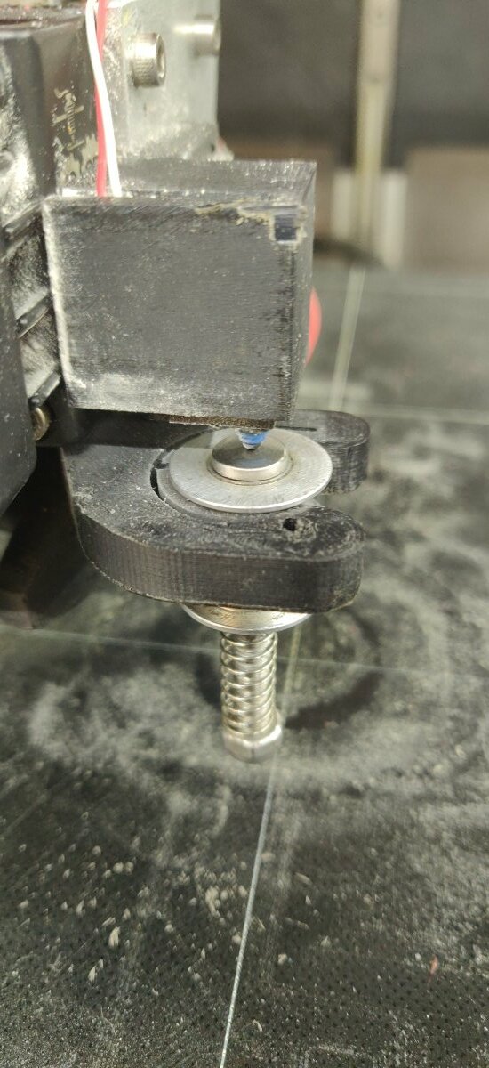
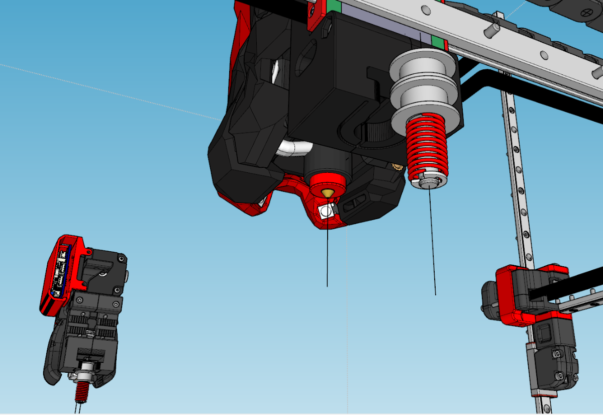
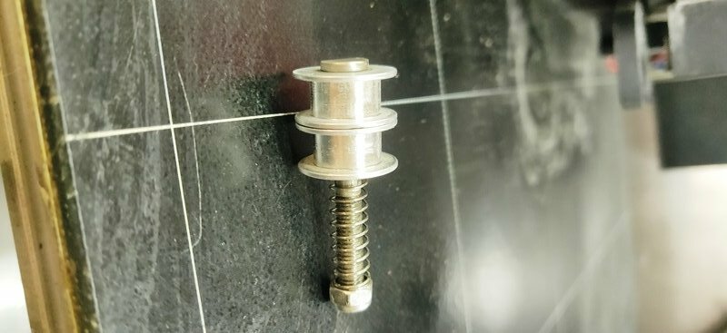
As a mechanical engineer I spend countless hours working out the mathematics, testing both the theoretical and practical aspects behind the many many ideas that pop into my head. He is a Video of a test of one version of my probe Dockable Probe I was driven to look for a suitable (to me) solution due to other units on offer (in my view) having multiple different issues, with the “popular” magnetic probe in my opinion being stupidly expensive compared to the sum of its parts, or with the likes of the Duet IR sensor which is very particular about reading (or not reading) the data produced by certain print surfaces, then the likes of a BL touch which shits the bed in a decently heated chamber 9anything above 50c), or inductive sensors providing huge reading variances due to reacting badly to temps. This led me into initially designing my own magnetic version of a collectable probe, but I encountered a problem after installing this type of probe in that the hot end and part cooling fan performance was compromised which led to prints failing, I tracked the issue down to a negative interaction between the magnetic field being produced by the fan motor windings being affected by the strength of the rare earth magnets used to hold the two parts of probe together. So that ruled out direct contact magnetic probes which led me on to a simplified version of what I have today. My design criteria were as follows The design must exceed the performance of other products on the market It needs to be inexpensive for the user to put together. It needs to employ readily available components of the same dimensions and standard across the world Its needs to operate in a manner where its presence does not negatively impact the performance of the machine in which it has been installed Parts count needs to be low; I am a great believer in the K.I.S.S methodology So on to the current iteration of my design There are three main printed parts, of a design that can be easily manipulated to allow simple mounting on almost any printer, there are other versions which are designed to fit specific printers such as the voron 2.4 with the stealth burner head. Those parts are printed in PC (ASA would be a suitable alternative) there are the two dock holders and the actuator switch holder. Then there is a simple switch which I modelled using the standard 3d printer end stop switch, with direct actuation on the contactor the switch is more than accurate There are two standard “smooth” idler pulleys used with 6mm belts and have bearing with an I/D of 5mm The actuator shaft can be a shouldered bolt or as my latest version uses a classic American car door hinge pin with is precision ground of a 5mm O/D and has a machined groove that allows a circlip to be attached (this retains the spring) And lastly an easily available 30mm long compression spring with an I/D of 6mm. On to the design If you look at the two idler pulleys, they are both the same and have specific sizes, THE O/D of the main inner surface is 12.15mm and the O/D of the Shoulder section is 17.85mm, the distance between the shoulders is 6.45mm so if you design (and print) the holders for the actuator to a specific tolerance you can achieve the desired goal. The main circular holder part of the dock is printed to be 0.10mm larger in diameter than the pulleys and the fingers of each dock partially encircles back around the pulley and those dimples are 0.10mm smaller in diameter than the pulley, the fingers are designed in such a way that they act like springs, upon entry to the dock the diameter of the pulley spreads these two dimples open allowing the pulley to enter the dock, once fully home the fingers spring to their normal shape and this spring action makes the fingers encircle the pully effectively adding a positive lock retaining action, that design is on both the head portion of the dock and on the storage portion. With regards stability and repeatability, the pulleys diameter and shoulders provide the stability holding the actuator very firmly in place, after the actuator has been “grabbed” and snapped in place, it does NOT matter if there is a minimal amount of lateral movement along the X/Y planes as that is not is what is going to be measured by the probe. Once the actuator has been collected and snapped into place the actuator shaft is forced to move upwards (as either the tool head lowers itself on the print surface in the manner cartesian and delta printers do or in the case of corexy the bed raises and lowers instead) this movement occurs as the actuator contacts the print surface, the actuator shafts O/D is a precision diameter which matches the I/D of the bearing inside the pulley which in this case is 5mm, the very close clearance tolerance between the shaft and the bearing means that things do not tilt on the Z axis plane enough to cause any measurement issue. The actuator is held in tension by its return spring and that tension is held against the precision machined surface of the upper bearing holding everything in a fully vertical position, the whole setup has been designed in such a way so that the distance between the base of the actuator which touches the print surface and physically actuates the end-stop switch means it travels LESS than HALF the distance between the top and bottom bearings, this has been a carefully calculated distance which ensures that the actuator shaft stays vertical throughout its travel during operation. The fact that pulleys have two shoulders which are of a larger diameter than the main retaining diameter means that further stability is ensured and as the distance between those shoulders is 6.45mm and that thickness of the dock itself is 6.35mm there is only a chance of the free play amount being 0.1mm but that is not being measured by the switch so it doesn’t matter, the length of the actuator rod is constant no matter what, and one the trigger height and offset has been calibrated repeatability stays pretty constant to a point of being almost imperceptible with a dial indicator.
-

Version 1.0.0
60 downloads
One of my goal was to print Polycarbonate (PC) as smoothly as possible. Unfortunately, PC is notorious for heavy warping. A possible countermeasure is to raise the chamber temp - in my case to around 60°C. (Be sure, that every component within your chamber can take the heat.) Around that temperature I found that the magnetic probe and the regular Micro-Switch probe aren't reliable anymore. So, I switched to a SSG-5P Micro-Switch, which is heat-resistant up to 120°C. The magnetic probe is a bit wider than the regular probe. Therefore, you have to reprint the X-Carriage. As of now, I redesigned the X-Carriage for CW1 - not CW2. Original probe made by Annex: https://github.com/Annex-Engineering/Quickdraw_Probe -
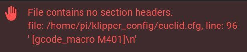
 I have removed the Inductive probe and installed a Euclid probe. I downloaded Euclid V3 example from Github. Using Fluidd interface I uploaded euclid.cfg I then entered all the parameters required. I also updated my printer.cfg file. I have followed a detailed video from Kapman's Basement Workshop. I have checked the syntax several times. If anyone can suggest something I would be grateful. I have added the Euclid.cfg and Config.cfg as attachments. euclid.cfg printer (3).cfg