Search the Community
Showing results for tags 'trident'.
-

Version 1.2.5
48,438 downloads
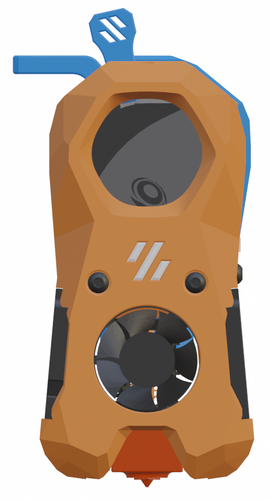
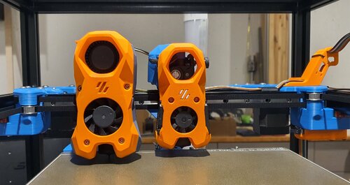
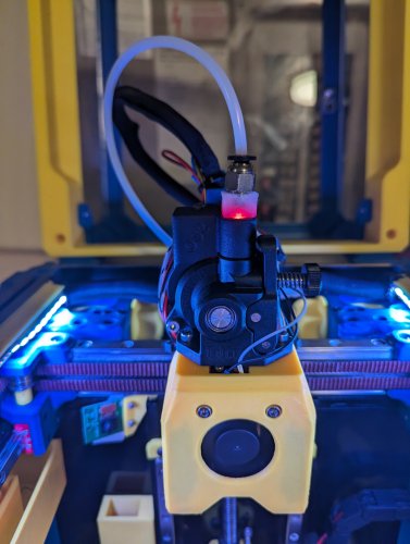
The Mini Stealth v2 toolhead is up on GitHub now. I will keep these files here as the new parts are not compatible with the v1.2.5 parts. I will support both versions in the comments here. I still need to create new assembly instructions but a lot of the steps are similar to what is described here. --------------------------------------------------------------------------- This toolhead scales down the body of the Stealthburner to a size which fits into a V0.1/V0.2. Fully assembled it weighs about 110 grams less than the original. It is designed around the Orbiter 2.0 extruder and has versions for the Phaetus Dragonfly, Dragon and Rapido HF hotends as well as versions for the Mosquito, the Revo Voron and the Creality Spider Pro hotends. It incorporates a status LED as well as two for print visibility. I have added new stretched versions that should fit the Rapido UHF, Dragon UHF and the VolcoMosq hotends. The Dragon UHF and Rapido UHF hotends can fit in the same shroud. The UHF hotends will reduce Z travel by 8.5mm and the VolcoMosq by 3mm. I cannot verify the fitment so if there are any issues please leave a comment. There are now two hex pattern inlays based on the design by 3DP-MAMSIH and a tutorial on how to apply them to the shroud. The negative body feature of Prusa/Super Slicer can also be used to create a crop-top version of the shroud as described at the end of the tutorial. The Mini Stealth uses a pair of 4010 blowers which produce more airflow than a 5015 blower while being notably less noisy and drawing less current. The depth of these fans do limit Y travel by 3mm on a V0.1 while the door is closed and tophat is on. The width of the main body at its base is also a very tight fit at the extremes of X travel. I have raised my tophat by 20mm which gives the cabling and filament tube plenty of room to breathe. The shroud fits a 3010 hotend fan or a 3007 fan by using a clip-in adapter. This Orbiter 2.0 Mini Stealth is a better fit than the Orbiter 1.5 Mini Stealth in a V2.4 or Trident as the motor no longer interferes with the path of the cable chain. There is a separate 'strain_relief' stl for use in the V0.1. There are also x-frame pieces that allow this Mini Stealth to be installed on a Switchwire. The nozzle is moved up by 3mm compared to the official Switchwire due to the stepper motor being so low on the Orbiter extruder but this also allows a BL-Touch to fit into the x-frame pieces. I have included a magnet mount and additional shroud .stl files to make this compatible with the ZeroClick mod. This toolhead also has versions that allow mounting a differential IR sensor. I have removed the mechanical Z endstop on my V0.1 and use the IR probe as an endstop and it has greatly simplified my homing sequence. There are additional x-frame pieces that allow mounting the Beacon3D probe, Euclid or Biqu MicroProbe for a V2.4, Trident or Switchwire. The included Blender file shows the entire assembly complete with screws and should answer most basic questions. Note on MGN-9 installation: The default 2mm x 10 plastic threading screw is too long for mounting the x-axis endstop. An M2 x 8 does the job fine. For mounting to the linear carriage use four M3 x 6 flat-head screws. Note: The MGN carriage shown is an MGN-9H, not the shorter MGN-9C used in the V0.1 mod. Preparation I recommend using a file to lightly remove any printing artifacts on the mating face of the shroud. Use a small file to smooth out the break-off edges of the LED PCB and make sure the LED pockets are clear of 'droopy bits' All three fans will need the wire retention piece clipped so the wires fit into the shroud channels easier. Differential IR Probe Installation The IR Probe needs to be screwed into place with two M2.5x8 FHCS before installing any of the fans, except with the VolcoMosq or UHF hotends where the probe needs to be glued on with CA glue. The Y-offset for this probe is 4mm in front of the nozzle and the X-offset is 32mm. I strongly recommend removing the 3-pin header and soldering wires directly to the probe PCB. When installed the wires will route out from the back of the IR probe cover to then join with the hotend and fan wires. I have included a cover to allow a connector at the probe but the wire management will be less than ideal.. Assembly Instructions After pressing the status LED diffuser into place, install the right part-cooling fan first by feeding the wires through the small hole at the bottom. Then feed the wires for the status LED and hotend fan through before starting to push the LED carrier into position. Carefully push the status LED carrier as far as it will go and press the fan into position while making sure not to pinch the part-cooling fan wires. Then press the remaining LEDs into their slots. (I measure out 35mm of wire to connect these LEDs together) Here is another view also showing where the hotend fan wires fit. Insert the second part-cooling fan and splice the wires together with the first fan. Install the hotend with at least two M2.5x6 screws (M3x6 for the Revo Voron). The heater cartridge should be installed away from the LEDs to avoid overheating them. (** don't forget the PTFE tube) Pre-assemble the extruder pieces before installing into the shroud. Use two M3x8 BHCS to install the Orbiter 2.0 extruder. It helps to have both screws in the Orbiter before putting it in place. Start the screw by the latch and then the blind screw should be easier to align. Gather all of the wires together with a zip-tie next to the base of the Orbiter latch and then use another zip-tie to secure the wires to the motor-bridge. Leave a little slack in the extruder wires. Install the strain_relief or cable_chain_mount with two M3x6/8 screws and the cable_door with a M3x10/12 screw. Close the cable door with a M3x6 BHCS and screw in the extruder tensioning thumb screw. Use two M3x40 BHCS to secure the toolhead to the x-carriage in a V0.1/V0.2. For installation in a Trident or V2.4 use two M3x50 BHCS. Happy Printing!- 683 comments
- 3 reviews
-
- 39
-

-

-

-
- orbiter 2.0
- v0.1
- (and 16 more)
-
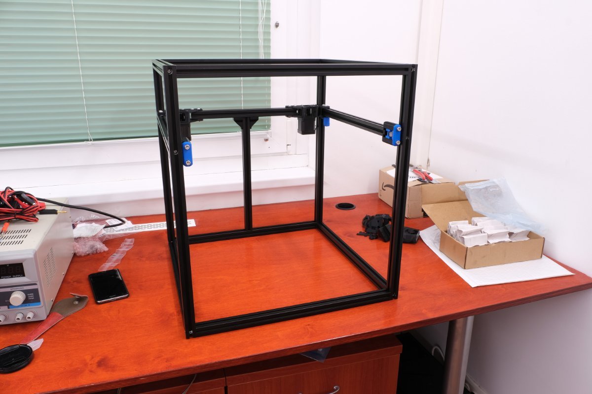
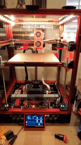
I've been jonesing to start this build for awhile, but got delayed by the various storms (delayed shipping) and then work and travel. I got my PIF parts from triponaduck which looked amazing, and have been working when I've had time the last week. Don't have time to work on it today so I thought I'd start writing some things up. So, working on either a workbench or on a large 2x2' terrazo (cheapest I could find) tile I mounted on some 1/4" ply to make a portable work surface. Putting together the frame was a joy. Just simply and satisfying. Came out nice and square. [[ I tried uploading images, but they come out as a solid color -- any hints? ]]
-
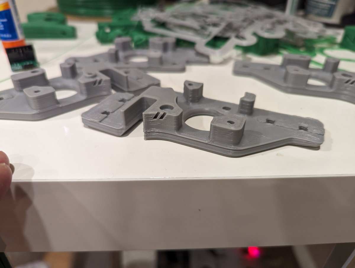
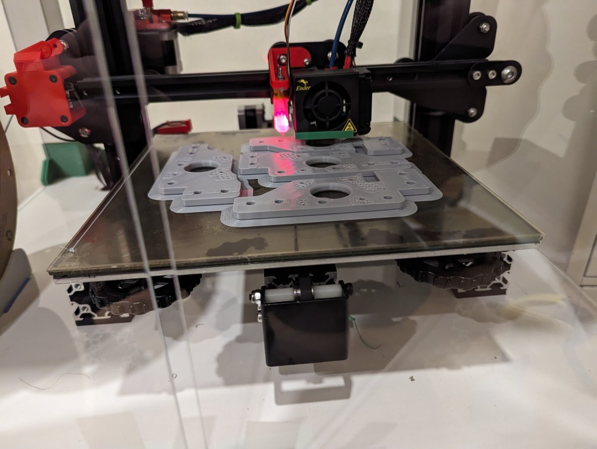
Took a while of debating myself: V0 "cheaper" entry and smol, V2 popular but Trident seemed underrepresented. Really it was mostly everyone saying Trident is a bit easier as the first Voron, and I can always build the others later on. So I ordered my Trident 350 formbot kit yesterday, they don't reopen until Monday. And then however long it takes to be shipped and make it to my door. Still plenty of things to do before then. Mainly: Working my way through the printed parts list and the stl files. Currently at 8% of parts according to it. Would be further but I detoured to bed adhesion problems when I tried the a/b drive frames. Printing on a smooth pei stuck to glass. Bought some gluesticks today and going to sleep on the reprints, they look like they should make it. Hopefully wont have to add too much more to the waste pile. And then there are the mods! I'm open to suggestions but so far: Stealthburner Inverted electronics https://www.teamfdm.com/files/file/526-trident-inverted-electronics/ TAP/Metal TAP/ChaoticLab? https://github.com/Vitalii3D-xyz/MetalTap - Still looking into them, but seems like doing tap now would save disassembling and adding later. Snap Latches https://www.teamfdm.com/files/file/392-snap-latch-2020/ Internal Spool https://www.teamfdm.com/files/file/537-horseshoespoolholder/ Probably Nevermore or another filter eventually
-
Version 1.0.0
0 downloads
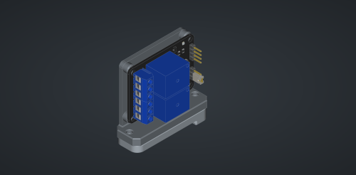
When space gets tight, parts need to be repositioned. I'm upgrading my little Voron 2.4-250 from a 24V Octopus setup to a 55V Kraken setup. The larger components make the electronics compartment very cramped, and I have to reposition some parts. One of them is the 2-relay board that turns the mainboard on and off. I now have to mount it vertically to save space... I'm using these old but small clips from the 2.4r1: https://github.com/VoronDesign/Voron-2/blob/V2.4r1/STLs/VORON2.4/Electronics_Compartment/DIN_Brackets/pcb_din_clip_x3.stl Relais Board: https://amzn.eu/d/37IFtSy I used M2 screws for the PCB and Clip Happy printing! -
Version 1.0.0
5 downloads
When space gets tight, parts need to be repositioned. I'm upgrading my little Voron 2.4-250 from a 24V Octopus setup to a 55V Kraken setup. The larger components make the electronics compartment very cramped, and I have to reposition some parts. One of them is the Raspberry Pi. I now have to mount it vertically to save some space... I'm using these old but small clips from the 2.4r1: https://github.com/VoronDesign/Voron-2/blob/V2.4r1/STLs/VORON2.4/Electronics_Compartment/DIN_Brackets/rs25_psu_bracket_clip.stl ... and 2 M3x10 screws for the Clip Happy printing -
Version 1.0.0
65 downloads
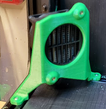
There are already several models available, but none of them really appealed to me. For my version, i used two truss bearings to guarantee smooth and play-free operation. BOM: 2x F695ZZ (5x13x4) 2x M3x20 Allen screws 2x Hammerhead nuts M3 1x M5x20 or M5x25 I drilled the M5 thread into the printed part. Happy printing!-
- 4
-
-
- ptfe
- ptfetubeguide
- (and 3 more)
-
I'll add my self sourced 250 Trident build to the diaries. This is my first Voron, and second printer. I started out with a Prusa Mini+ kit and enjoyed the build so much that I started looking more seriously at the Vorons. I did look while doing initial research, but the full DIY nature was intimidating at the time; the Mini has been a great learning printer both for building and printing. In the process of researching I found the Voron Discord, this forum, and Nero & Steve's Youtube channels. Lurking, reading, and ultimately starting to ask dumb questions has taught me a lot in a short time. So I started with the Voron configurator to get my BOM, then grabbed the matching info off the sourcing guide to start finding where to buy parts. I spent quite a while learning about many of the components to determine what the best cost vs quality balance is for me. In the process, I found the popular vendors supplying the hobby. I built myself a spreadsheet to track & manage the list of parts and my often-shifting plans of what to buy and from whom. I started purchases taking advantage of sales on Aliexpress, and just accelerated the process after witnessing the Voron Hug and general supply chain issues. If something is in stock these days, you probably want to buy now rather than wait. So the list of vendors I've used are: 3D Maker Parts Amazon Aliexpress DFH Grainger KB-3D Mandala Rose Works PiHut Push Plastics Sparta 3D West 3D I tried to minimise the orders and take advantage of free shipping triggers as much as possible, so I didn't get hit too hard with that forgotten cost. A few redirected sources due to out of stock situations; PiHut most notable--had to order the board from the UK after the things became unobtanium. The last part to get is ironically the frame. I'm being picky and want the LDO blue kit which has not been available. As I was composing this I checked again, and unexpectedly got a hit on KB-3D, who now has them! So all parts are now ordered. I've spent the last week getting my Mini prepped for printing up the parts for the Trident. So I now have a full set of spare parts in PETG, which itself was a learning experience. I have to move the OctoPi from a separate case to the integrated electronics box lid. That is to help fit everything under the original box for the Mini as my cheap enclosure for ABS printing. Next step is to get some ABS test prints so I can dial that in, then start printing parts. EDIT: I should probably also list the mods I am incorporating into the initial build: hartk SexBolt Z endstop. hartk Z endstop PCB randell XY endstop PCB jeoje 4.3" Waveshare touchscreen with Steve's modified skirt. hernsl magnetic bottom panel clips Steve's no tape skirt fan mounts chrisgonzales 270° door hinges Nero's idler bearing stack in place of toothed idler change
- 116 replies
-
- 3
-
-
- selfsourced
- builddiary
- (and 2 more)
-
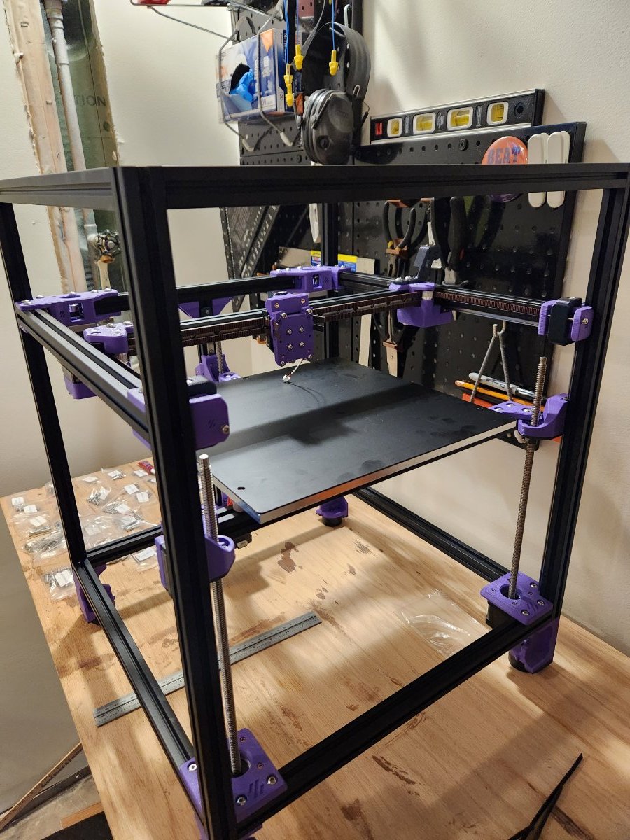
Hi everyone, I started my first ever build a few weeks ago that I'm hoping to chip away at as I have time. I chose the Formbot Trident 300 kit with the dragon uhf as a good balance of performance and price. My first post will be a bit of a dump of the progress made so far, and then I hope to do some more real time updates after that. I'm looking forward to sharing my progress with everyone and hearing what you have to say! As a sneak peek, here is where I am so far.
-

Version 2
2,573 downloads
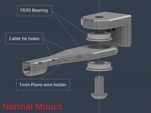
V2- PTFE bowden tube guide and CANBUS wire support I've made some adjustment after some feedback from the community. Changes made over V1: Added a option to have F695 bearings incorporated Enlarged the tube opening Added cable/zip tie openings Added spot for 1mm piano wire if needed. Recommended print settings: Voron print settings (4 walls, 40% infill and 5 top and bottom layers) Turn off thin walls Bridge setting: keep only bridges (watch out for bridging for cable tie holes) 0.2mm layers and 0.2mm first layer No need to adjust for ABS shrinkage Required Hardware: M3x8 Bolt and M3 T-nut M5 bolt to suit option. Optional M5 nut if you can fit it with the bearing option. V1 - PTFE bowden tube guide and CANBUS wire support This is can found inside the zip files and of the initial release Required Hardware: M3x8 Bolt and M3 T-nut M5x10 Bolt or a M5x8/12 Optional 4mm drill bit for cleaning out bowden tube path About In my 350 build the PTFE tube kept getting caught so I made this arm to keep it up. The shorter arm works better so I recommend using it instead The setup has also been used by a few user to support their CANBUS wires (zip tied to the reverse bowden) Install Drill out bowden guide with 4mm drill bit for a perfect fit (optional) Bolt mount to rear frame with M3x8 and tnut putting the lip at the top Screw arm on with M5x10 (I used a M5x8mm and it works fine) into the plastic allowing the arm to still be able to swivel- 3 comments
- 1 review
-
- 15
-
-
- canbus
- galvanicglaze
- (and 3 more)
-
Version 1.2.5
23,612 downloads
The Mini Stealth v2 toolhead is up on GitHub now. I will keep these files here as the new parts are not compatible with the v1.2.5 parts. I will support both versions in the comments here. I still need to create new assembly instructions but a lot of the steps are similar to what is described here. --------------------------------------------------------------------------- This toolhead scales down the body of the Stealthburner to a size which fits into a V0.1/2. Fully assembled it weighs less than 260 grams. It is designed around the Mini Sherpa extruder and has versions for the Phaetus Dragonfly, Dragon and Rapido HF hotends as well as versions for the Mosquito, the Revo Voron and the Creality Spider Pro hotends. It incorporates a status LED as well as two for print visibility. I have also added stretched versions that should fit the Rapido UHF, Dragon UHF and the VolcoMosq hotends. The Dragon UHF and Rapido UHF hotends can fit in the same shroud. The UHF hotends will reduce Z travel by 8.5mm and the VolcoMosq by 3mm. I cannot verify the fitment so if there are any issues please leave a comment. There are now two hex pattern inlays based on the design by 3DP-MAMSIH and a tutorial on how to apply them to the shroud. The negative body feature of Prusa/Super Slicer can also be used to create a crop-top version of the shroud as described at the end of the tutorial. The shroud uses a pair of 4010 blowers which produce more airflow than a 5015 blower while also being notably less noisy and drawing less current. The depth of these fans do limit Y travel by 3mm on a V0.1 while the door is closed and tophat is on. The width of the main body at its base is also a very tight fit at the extremes of X travel. The shroud fits a 3010 hotend fan or a 3007 fan by using a clip-in adapter. This Mini Stealth - Mini Sherpa also fits well in a V2.4 or Trident and modified x-frame left and right pieces are included. There are cable chain mounts as well as strain_relief and umbilical_PCB mount for use in the V0.1. There are additional x-frame pieces that allow this Mini Stealth to be installed on a Switchwire. The nozzle is moved up by 3mm compared to the official Switchwire. The x-frame has geometry that allows a BL-Touch to fit locked between the two pieces. I have included a magnet mount and additional shroud .stl files to make this compatible with the ZeroClick mod. This toolhead also has versions that allow mounting a differential IR sensor. I have removed the mechanical Z endstop on my V0.1 and use the IR probe as an endstop and it has greatly simplified my homing sequence. There are additional x-frame pieces that allow mounting the Beacon3D probe, Euclid or Biqu MicroProbe for a V2.4, Trident or Switchwire. The included Blender file shows the entire assembly complete with screws and should answer most basic questions. Note on MGN-9 installation: The default 2mm x 10 plastic threading screw is too long for mounting the x-axis endstop. An M2 x 8 does the job fine. For mounting to the linear carriage use four M3 x 6 flat-head screws. Note: The MGN carriage shown is an MGN-9H, not the shorter MGN-9C used in the V0.1 mod. Preparation I recommend using a file to lightly remove any printing artifacts on the mating face of the shroud. Use a small file to smooth out the break-off edges of the LED PCB and make sure the LED pockets are clear of 'droopy bits' All three fans will need the wire retention piece clipped so the wires fit into the shroud channels easier. Differential IR Probe Installation The IR Probe needs to be screwed into place with two M2.5x8 FHCS before installing any of the fans, except with the VolcoMosq or UHF hotends where the probe needs to be glued on with CA glue. The Y-offset for this probe is 4mm in front of the nozzle and the X-offset is 32mm. I strongly recommend removing the 3-pin header and soldering wires directly to the probe PCB. When installed the wires will route out from the back of the IR probe cover to then join with the hotend and fan wires. I have included a cover to allow a connector at the probe but the wire management will be less than ideal.. Assembly Instructions After pressing the status LED diffuser into place, install the right part-cooling fan first by feeding the wires through the small hole at the bottom. Then feed the wires for the status LED and hotend fan through before starting to push the LED carrier into position. Carefully push the status LED carrier as far as it will go and press the fan into position while making sure not to pinch the part-cooling fan wires. Then press the remaining LEDs into their slots. (I measure out 35mm of wire to connect these LEDs together) Here is another view also showing how the hotend fan wires fit through the hole on the side of the status LED carrier. Insert the second part-cooling fan and splice the wires together with the first fan. Install the hotend with at least two M2.5x6 screws (M3x6 for the Revo Voron). The heater cartridge should be installed away from the LEDs to avoid overheating them. ( ** don't forget the PTFE tube ) Pre-assemble the extruder with your chosen cable management using M3x20 BHCS before installing into the shroud. Install the extruder with two M3x8 BHCS. Make sure that the LED and fan wires route around and exit behind the extruder. They can even fit in the gap below the extruder as shown in the picture. Gather the wires together with zip ties and secure them up to the cable management piece. Do your best to keep them tucked in close at the base of the extruder. I used a temporary zip tie at the top to keep the wires manageable until I installed the toolhead in the printer. The top of the cable door hooks under the back of the shroud and then you can use 2 - M3x6 BHCS to secure the cable door in place. Use two M3x40 BHCS to secure the toolhead to the x-carriage in a V0.1/V0.2. For installation in a Trident or V2.4 use two M3x50 BHCS. Happy Printing!- 75 comments
- 1 review
-
- 23
-
-
-
-
- mini sherpa
- stealthburner
- (and 16 more)
-
Version 1.0.0
94 downloads
I wanted to reach ABS/ASA temperatures faster, and be able to maintain 55-60°C for those larger warp-prone prints, so I designed this chamber heater mount. If you're going to attempt this, make sure to use a temperature fuse to protect your printer (and your house) from burning down in the event of failure/over-heating. I used 2x 3mmx5mm long heatserts inserted from the front, and 3mmx12mm screws to attach the heater. 4x 3mm t-nuts and 4x 3mmx10mm screws are required for mounting the bracket. I used this 120VAC 250W heater (with 12VDC fan): https://www.amazon.ca/dp/B07NYX5DKD?psc=1&ref=ppx_yo2ov_dt_b_product_details I used this SSR: https://www.amazon.ca/dp/B06WLNHPWK?psc=1&ref=ppx_yo2ov_dt_b_product_details I loosely followed the chamber heater post from @ahough, and this would've been way harder (nigh impossible) without their post and the comments section. Notable mention goes out to @Dousi as well, since I copied and modified their config example to use as my own. I hope the configs below help someone else along their way. ******** ******** Here is my chamber heater section within my printer.cfg file: ******** ##################################################################### # CHAMBER HEATER ##################################################################### [thermistor chamber_thermistor] #define "chamber_thermistor" characteristics temperature1: 25 resistance1: 100000 beta: 3950 [thermistor heater_thermistor] #define "heater_thermistor" characteristics temperature1: 0.0 resistance1: 32116.0 temperature2: 40.0 resistance2: 5309.0 temperature3: 80.0 resistance3: 1228.0 [temperature_sensor heater_temp] #this is the temp sensor for the 10K probe inserted in the heater core sensor_type: heater_thermistor #use temp sensor characteristics as defined in "heater_thermistor" sensor_pin: PA2 #Manta 8P temp sensor input pin. This temp probe is glued to the heater core with UV resin min_temp: -100 #set minimum temp before error/shutdown max_temp: 140 #SAFETY max heater core temperature, printer will shutdown above this temp [heater_generic chamber_heater] #setup chamber heater heater_pin: PE3 #Manta 8P heater output pin to SSR. This temp probe is mounted near the top of my chamber sensor_type: chamber_thermistor #use temp sensor characteristics as defined in "chamber_thermistor" sensor_pin: PA1 #Manta *P temp sensor input pin control: watermark #use watermark control method (on/off) max_delta: 0.1 #set the delta temp to energize/deenergize chamber heater max_power: 1.0 #set maximum power of heater 1.0 = 100% min_temp: -100 #set minimum temp before error/shutdown max_temp: 70 #SAFETY max chamber temperature, printer will shutdown above this temp pwm_cycle_time: 0.01666 #Set this to avoid room lights flickering on higher power heaters. This value works well for 60Hz power. 0.1 is 10Hz [verify_heater chamber_heater] #setup chamber heater verification parameters max_error: 120 check_gain_time: 240 hysteresis: 5 heating_gain: 1 [heater_fan heater_fan] #setup fan attached to back of chamber heater pin: PE4 #Manta 8P fan output pin. Jumper selected for 12V max_power: 1.0 #set maximum power of fan 1.0 = 100% heater: chamber_heater #when "chamber_heater" is ON fan will be ON heater_temp: 30 #fan will turn off below this level ##################################################################### # MACROS ##################################################################### [gcode_macro M191] gcode: {% set S = params.S | default(0) | float %} SET_HEATER_TEMPERATURE HEATER=chamber_heater TARGET={S} M118 Chamber heating to {S}C M118 Waiting for chamber heating... TEMPERATURE_WAIT SENSOR="heater_generic chamber_heater" MINIMUM={S} M118 Chamber heating {S}C is done. ******** ******** I also run Ellis' bedfans, and modified bedfans.cfg, "Command overrides" section to the below: ******** ############ Command overrides ############ # Override, set fan speeds to low and start monitoring loop. [gcode_macro SET_HEATER_TEMPERATURE] rename_existing: _SET_HEATER_TEMPERATURE gcode: # Parameters {% set HEATER = params.HEATER|default("None") %} {% set TARGET = params.TARGET|default(0)|int %} # Vars {% set THRESHOLD = printer["gcode_macro _BEDFANVARS"].threshold|int %} {% if HEATER|lower == "extruder" %} M104 S{TARGET} {% elif HEATER|lower == "heater_bed" %} M99140 S{TARGET} {% elif HEATER|lower == "chamber_heater" %} _SET_HEATER_TEMPERATURE HEATER=chamber_heater TARGET={TARGET} {% else %} {action_respond_info("Heater %s not supported" % HEATER)} {% endif %} # Set fans to low if heater_bed temp is requested above threshold temp, and kick off monitoring loop. {% if HEATER|lower == "heater_bed" %} {% if TARGET >= THRESHOLD %} BEDFANSSLOW UPDATE_DELAYED_GCODE ID=bedfanloop DURATION=1 {% else %} BEDFANSOFF UPDATE_DELAYED_GCODE ID=bedfanloop DURATION=0 # Cancel bed fan loop if it's running {% endif %} {% endif %} ******** ******** II then modified my PRINT_START macro to include the chamber heater stuff as seen below: ******** [gcode_macro PRINT_START] # Use PRINT_START for the slicer starting script - PLEASE CUSTOMISE THE SCRIPT gcode: EXCLUDE_OBJECT_DEFINE BED_MESH_PROFILE load=default # Load variables {% set bed_temp = params.BED|default(60)|int %} {% set extruder_temp = params.EXTRUDER|default(230)|int %} {% set CHAMBER_TEMP = params.CHAMBER|default(20)|float %} M104 S150 #start nozzle heating, keep below oozing temp M117 Extruder Heating... M140 S{bed_temp} #set bed temp to "bed_temp" and move on M117 Bed Heating.... M190 S{bed_temp} #allow bed to get up to temperature M117 Heating Chamber... M191 S{CHAMBER_TEMP} G90 #Use absolute coordinates M117 Homing... G28 M117 Adjusting Z Tilt... Z_TILT_ADJUST G28 M117 Calibrating Bed Mesh... BED_MESH_CALIBRATE M117 Waiting for Extruder to Reach Printing Temperature... M109 S{extruder_temp} G92 E0 #Reset exruder M117 Purging Filament... ADAPTIVE_PURGE M117 ******** ******** I use CURA and this is my Start Gcode as defined within Cura: ******** ;Nozzle diameter = {machine_nozzle_size} ;Filament type = {material_type} ;Filament name = {material_name} M204 P500.00 R1000.00 T500.00 ;Setup Print/Retract/Travel acceleration M220 S100 ;Reset Feedrate M221 S100 ;Reset Flowrate M117 PRINT_START EXTRUDER={material_print_temperature_layer_0} BED={material_bed_temperature_layer_0} CHAMBER={build_volume_temperature} -
Version 1.0.0
40 downloads
-------------English/Englisch------------- Hey everyone! I whipped up this wall mount for my Voron 2.4 because I was tired of all the vibrations while printing. Plus, it keeps the printer from sliding around at high speeds. So far, it’s been awesome! What It Does: Flexible Use: You can mount it in any orientation. No need to mirror anything in your slicer – just print it 2x or more, depending on how many mounts you need. Cable Pass-Through: A lot of folks hide cables in the aluminum profiles, but that gets tricky when you want to screw something onto them. So, I added a cable slot to this mount – just run the cable through there. (You might need to re-crimp it, though.) Maybe for Other Printers: I made it for the Voron 2.4, but it could work with other printers using 2020 aluminum extrusion, like the Trident. Give it a shot and see! Testing Phase: I’m currently testing it on my Voron 2.4, and it’s making a real difference. Less wobble, the printer stays put, and I think it’s even a bit quieter (since the vibrations go straight into the wall and get “swallowed” there). Print Tips: Filament: I printed mine in ASA (had some leftovers lying around). ABS or PETG should work fine too. PLA might do the job with a few extra wall loops. Layer Height: I went with 0.2 mm – works for me. Infill: I used 40%, but if your printer’s on the heavy side, maybe bump it up a bit. Supports: Shouldn’t need them, except maybe at the wall interface area. If so, just keep Supports on printbed only. The cable slot has some light bridging, but it’s no big deal – you can add support for better quality if you want, but it’s barely necessary. Assembly Tips: After printing, grab 4 rotating T-nuts and 4 M3x10 screws per mount and slide them into the profile. For my setup, I placed the mounts on the left and right at the back, about 25 cm from the top of the printer. Tighten them up properly (with the 4 bolts), then mark the drill holes on the wall (use a center punch or hole marker). Drill the holes into the wall and add anchors. (Depending on your wall type, you might be able to screw straight in.) Thanks to the mount’s shape, you can easily get to all the holes and screws If you want, use the cable slot to run a cable through (like for build chamber lighting, for example). -------------German/Deutsch------------- Hi zusammen! Ich hab diese Wandhalterung für meinen Voron 2.4 gebastelt, weil ich die Schwingungen beim Drucken loswerden wollte. Außerdem hält sie den Drucker fest, damit er bei hohen Geschwindigkeiten nicht verrutscht. Bis jetzt echt top! Was sie kann: Flexibel einsetzbar: Du kannst die Halterung in jeder Orientierung verwenden. Es muss beim Druck also nichts gespiegelt werden. Einfach 2x oder öfter drucken, je nachdem wie viele Halter du benötigst. Kabeldurchlass: Viele Nutzer verstecken Kabel in den Aluminiumprofilen. Das Problem ist dann, dass die Kabel im Weg sind, wenn etwas an die Profile angeschraubt werden soll. Ich habe daher einen Kabeldurchlass mit in die Halterung eingefügt, damit man das Kabel dort einfach durchführen kann. (Möglicherweise muss man es jedoch neu Krimpen. Vielleicht auch für andere: Ich hab die Halterung primär für den Voron 2.4 erstellt, aber sie sollte theoretisch auch bei anderen Druckern mit 2020er Aluminiumprofilen funktionieren, z. B. dem Trident. Einfach mal ausprobieren! Testphase: Ich teste sie gerade an meinem Voron 2.4, und sie macht echt einen Unterschied. Weniger Wackeln, Drucker bleibt stabil und meines Erachtens sogar etwas leiser (da die Schwingungen direkt in die Wand übertragen werden und dort “geschluckt” werden. Druck-Tipps: Filament: ich habe sie in ASA gedruckt (hatte noch ausreichend “Rest” da. ABS oder PETG sollten auch Funktionieren. PLA möglicherweise mit ein paar mehr Wandschleifen auch. Schichthöhe: 0,2 mm hab ich genommen Füllung: Ich habe 40% verwendet, aber bei schwereren Druckern vielleicht mehr reinpacken. Stützen: Sollten nicht notwendig sein (bis auf den Bereich des Wandinterfaces. Wenn, dann nur auf dem Druckbett. Der Kabelschlitz hat so kleines Bridging, dass es nicht notwendig ist. Für Bessere Qualität kann man es natürlich mit Support drucken, aber es sollte wie gesagt nur wenig support notwendig sein. Montage-Tipps: Nach dem Druck dann einfach je Halter 4 rotierende Nutensteine (T-nuts) und 4 M3x10 Schrauben verwenden und in das Profil einführen. In meinem Fall habe ich die Halter links und rechts an der Rückseite positioniert, ca 25cm von der Oberkante des Druckers. Hier die Halter dann richtig Festschrauben (mit den 4 Bolzen) und die Bohrlöcher an die Wand übertragen (Körner oder Bohrloch-Marker) Die Löcher dann in die Wand Bohren und mit Dübeln versehen. (Je nachdem was für eine Wand ihr habt, könnt Ihr jedoch direkt reinschrauben) Durch die Form des Halters kommt man an alle Löcher / Schrauben bequem heran Wer will kann dann auch die Kabelführung verwenden um dort ein Kabel (zum Beispiel für die Beleuchtung des Bauraumes) hindurch zu führen. -
Version 1.0.0
134 downloads
As I'm currently swapping to hartk1213's pinmod I was wondering why A/B Drive Units have different Pin length (28/30mm). when looking at his STL's I saw the reason that one pin is secured against vertical down-movement by adding a 2mm stop, but not the 2nd what made no sense to me. So I got his Step and looked to the specific lower A/B plates, but the.step doesn't correspond to the downloadable STL's as there are no stops in the .step parts? Anyway, I decided to modify to have both pins secured and made 2 versions: 2 times 5x28mm or 2 times 5x29mm pins per side. so for both sides 4 pins are needed! The 29mm Version makes more sense to me as the pin has 4mm guidance in the unit and I think 1mm stop to secure the pin should be enough. I found the pins at Aliexpress: https://www.aliexpress.com/item/32769265211.html -
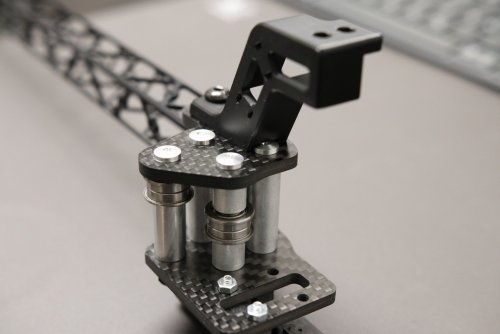
History I am a proud Aquila owner... or used to be. I modded its electronics, the Z-drive, the extruder, added extra part cooling and swapped out the fan duct, made the heatbreak all-metal, encased it, klipperized it, made it virtually silent (fan+electronics mods), added a BLTouch, exchanged the glass plate for powdered PEI, added better bed springs... and honestly, based on other prints I've seen both IRL and online, its print quality could put a lot of premium printers to shame now. But still I've become dissatisfied with this bedslinger. Obviously my mods solved many of its initial issues, but I still constantly fight with first-layer adhesion and can never use the whole bed. Also, some components often need maintenance every few prints. Add to this that printing ABS is still problematic, and printing anything tall is impossible at humane speeds due to the moving bed, I've decided: I'm gonna build myself a Voron The Goals My choice fell to the Trident in its 300mm size. My expectations is that when it is done, it should be much more reliable than my current printer, and I'll also get a larger build volume and better ABS printability. I guess it will also end up being faster which is certainly good, but that really is only a secondary goal for me. Let's see if I can make it. Right from the start I am planning with a bunch of mods (checkmark indicates finished installation): ✓ Galileo2 extruder ✓ TAP ✓ CAN with umbilical cable ✓ Kinematic bed mount ✓ Y-axis backers ✓ WobbleX ✓ An ultra-flat bed from MRW (without integrated magnets) ✓ BFI ✓ Magnetic acrylic panels ✓ Chamber thermistor ✓ Nevermore filter (also acting as bed fans) ✓ Chamber lighting ✓ Voron Revo hotend ✓ Nozzle brush and purge bucket About the mods Just a few days ago, the Galileo2 (well, it's public beta) was announced and a small stock even became available with instant delivery (no waiting until sometime in october) at a local store. I might have gone into over-hype mode, but I am intrigued by the G2 and since it was optimized first and foremost for extrusion consistency, I decided I'll order one and ditch my Clockwork2 even though I already ordered the parts for it a week ago. Before the G2, my plan was to mod the CW2 with Bondtech's IDGA. The G2 is also supposed to be quieter which I also welcome: I've been told that Vorons can be pretty loud to begin with, and considering that my current printer is very silent, I'm already afraid the contrast in noise levels will be uncomfortable. So any help is welcome. I'm sure a lot of people would question the inclusion of the WobbleX. Well, I fervently dug through many forums and the Voron Discord before assembling my BOM, and even though most people claim they don't have problems with Z-banding, it also doesn't seem to be an unheard phenomenon on the Trident or similar printers (like the V-Core). I decided I'd rather get rid of the problem from the get-go even if there is a good chance I might not need it. Don't judge me please. The bed stuff with the MRW bed, kinematic mounts and backers are due to my first-layer traumas from my current printer. Besides, the kinematic mount might also save a lot of time when doing smaller prints by not having to wait for the printer to warm up. Let's see if this theory holds up in practice. For the backers I ordered linear guides. This sounds like a Gucci move but not at all. Rails that serve as backers don't have the same quality requirements as the rails with the actual carriages, so these can be dirt-cheap. Hence I ordered the cheapest set I could find on Aliexpress. This way, price was not only lower than Titanium backers, but at the same time I'll even get better print results. You might not want to do this though if you're not building an umbilical toolhead, as the cable chain would be in the way. My build's umbilical though, so no problem here. The reason for the Nevermore, chamber thermistor and bed fans should be obvious: All for the sake of printing ABS. Related to this are the magnetic acrylic sheets. Being magnetic will allow me to easily remove them or snap them back in, making it a child's play to switch from ABS to PLA and back. I did not include the pinmod. This mod is so strange. It seems to be extremely popular, it is present in many kits, and if not in a kit a very large portion of users still implement it. All this despite not having seen a single post or analysis or report where it actually made things better. If experts or highly-respected members of the Voron community are asked, they unanimously claim this is a useless mod and there is no reason to include it. So I left it out based on multiple people's advice and I'm glad I did: I'm past assembling the idlers in the build process, and what I see now myself is that the pinmod should not make any difference (the screws/pins are not what the bearings directly rotate around), so it is no surprise if it doesn't. IMHO, the pinmod is basically snake-oil. Maybe not really a mod, but it might be worth noting I opted for a BTT Pi+U2C in the electronics compartment. The nice thing about this is two-fold: First, the BTT Pi can be powered by 24V directly, so you save the space and cabling for a separate 5V PSU. Second, the U2C can piggy-back on the BTT Pi, saving again space and cabling. There is enough space so it's not like you need to save it, but this will make everything much tidier, neater and even easier to wire up. I'll completely ditch the screen. My current printer has one but I still use it exclusively over the Fluidd web-UI only. I know I won't need a screen on my Voron by experience. The self-sourcing My self-sourcing experience was a mixed-bag at first. It is very time-intensive, for me it cost multiple days all things considered. I fully understand if not all people are willing to go through this process. The upside is you can control the brands and quality of the components, whereas with kits this is either unknown or at least might fluctuate. It might be tempting to think that self-sourcing is cheaper, but this depends on a lot of factors: what components you already have, what components are redundant to you in the kit due to future mods, how is component availability in stores, and even where you live (due to VAT amount or shipping costs). You also need to optimize shipments to order from as few stores as possible. Simply taking a kit's price and adding those of my components that weren't in the kit doesn't offer a full picture, and I didn't make this calculation. Of course, at first glance the completed BOM ended up being much more expensive than a kit, totaling to about 2400 EUR incl. VAT and shipping. This might sound scary compared to a kit's price that sells for around 1500 EUR, but considering all the extra stuff I ordered (PIF parts, TAP, CAN, MRW bed, Delta fans, WobbleX, Kinematic mount, twice the extruder, a quality crimping tool and allen-key set, chamber lighting, ...), I think I did pretty good. I am not sure a kit would have been cheaper, and even if it were, not by much. Unfortunately, I also used to be pretty sure that even if I saved some money by self-sourcing, I did not save much. Frankly, between all the extra time, work and headache it might not have been worth it. At least that's what I thought at first. Then yesterday, I saw Lecktor's announcement about their fully-modded all-extra 2.4 kits. Yeah, I know it's a 2.4 and not a Trident. Yeah, I see the mods list is different from my own. Still, it is a lot more comparable BOM to my build than any other kit. Their prices start at ~2200EUR (excl. VAT!), so this makes me think I have grossly underestimated the money I saved by self-sourcing. What do you think? The build I started building last weekend (16. Sept). The printed parts are PIF parts and I have nothing to complain about. They are made out of FormFutura's "Premium ABS", the accent color being "Ocean Blue". Unfortunately, the guys at Lecktor were in sleep mode apparently and they did not ship my order for a whole week. This resulted in most mechanical stuff having arrived on time except for the Lecktor parcel. Since that parcel contains all the Z-drive components and all the non-backer rails, all I could do for now is assemble the frame and the idlers. Nevertheless, the first mod is in place Squareness seems good. This is not exact but deviations between diagonals seem to be around or under 0.5mm. I built the frame on my kitchen countertop to help with that (the bench in the picture is not it), and I did not need to do any readjusting afterwards. The bed got the Keenovo heater applied but is waiting for the GraviFlex foil (also in the Lecktor parcel arrgh...). To be continued... (don't worry, the rest of the posts should be shorter, lol)
-
Version 2022.03.31
16,750 downloads
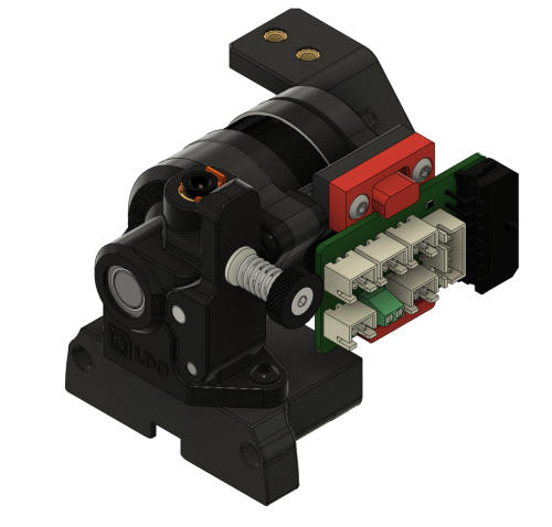
Orbiter 2 Clockwork Module (beta) This Clockwork module allows the use of the Orbiter v2 Extruder in the Voron Afterburner. THIS IS A PRE-RELEASE - DO NOT DOWNLOAD UNLESS YOU ARE WILLING TO DEAL WITH POSSIBLE ISSUE OR TO GIVE FEEDBACK! The rear screws that hold the chain anchor on are m3x8, two of them. They use the Voron heat set inserts, m3 I was working with DoubleT on the PCB holder. Trying to build a universal tool version so we could use different holders.- 84 comments
-
- 24
-
-
-
-
- orbiter2
- spacelab2021
- (and 4 more)
-
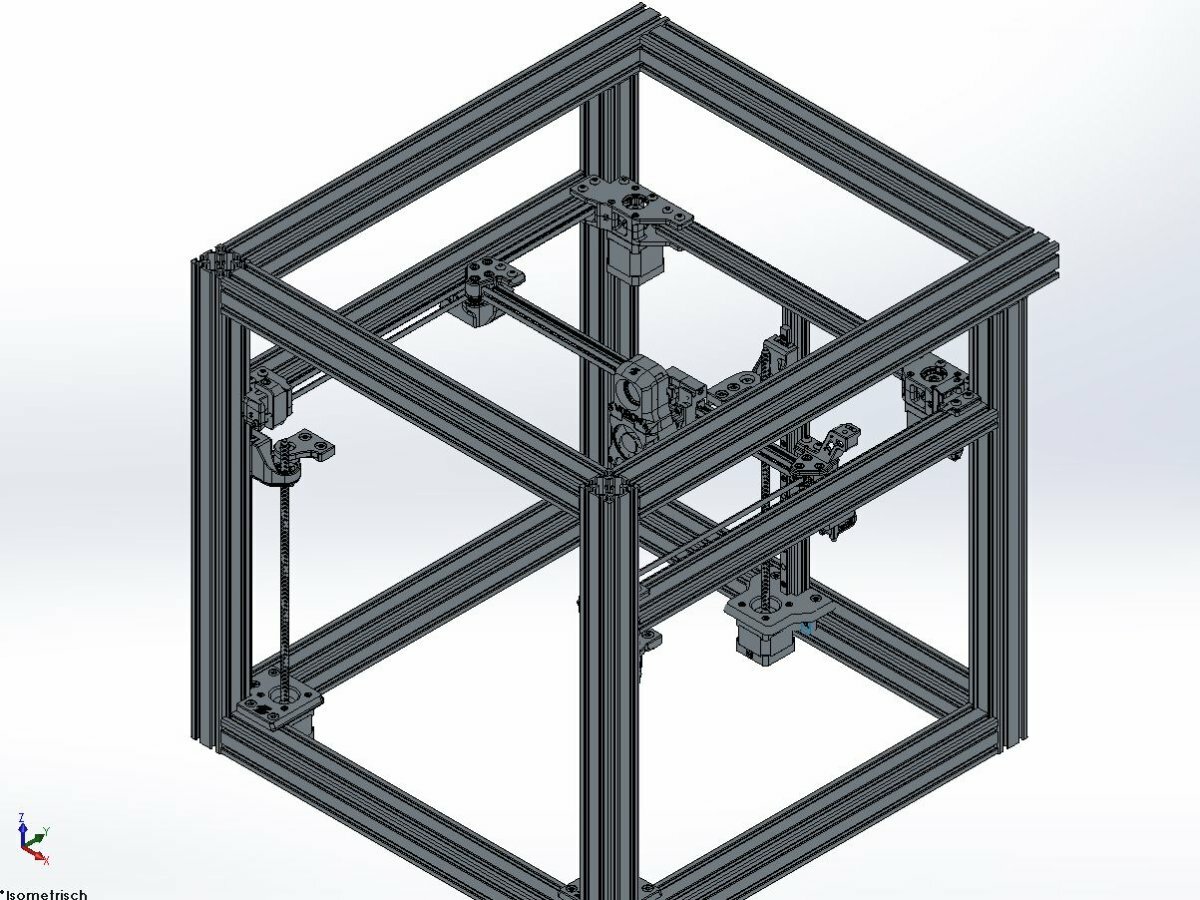
Hi, i want to build a trident with 350 to 350 mm. - I want a very strong frame and so i will use 40x40 slot 5 profiles (don't know "slot 5" is a valid translation) - I am not sure i like the cable chains, so my frame should be open for an umbilical solution (no can bus) - I plan to use a dragon standard, an orbiter 2 or LTX lite extruder and an octopus pro - no hall sensors There are still many open decisions, because I still have to gather some knowledge. This is the state of my planing.
-
Version 2022.04.17
563 downloads
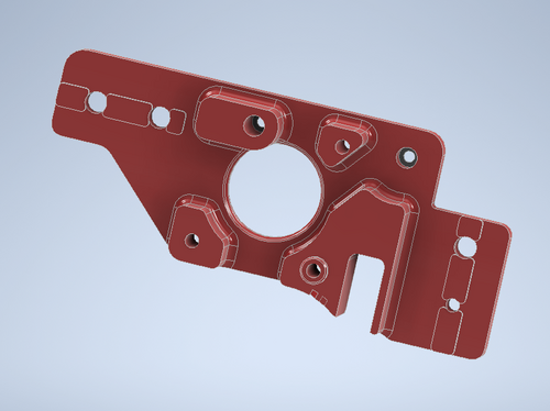
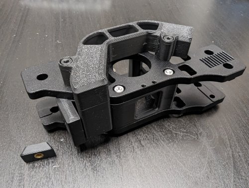
Trident Inverted Electronics Bay Mod (but can be used for the 2.4 as well with a hinged bed mod) Major update to align with 2.4r2 fan mounts! Included in the CAD (but not STLs) are the V2.4r2 skirt screw-on fan mounts. The STLs are available from the 2.4r2 STL repository. Newly added: C shaped din rail supports so no additional hardware is required. Also allows rails to be more easily installed front to back of printer if desired, as the C shape allows them to be installed around the power inlet and PiPlate. You do not need custom panels! The front Z stepper mounts have been modified to remove the captive part of the plate that locked the panel in place, so it can be just dropped in as shown in the animated gif below. No additional hardware required, BOM parts only. -
Version 1.2.5
22,551 downloads
The Mini Stealth v2 toolhead is up on GitHub now. I will keep these files here as the new parts are not compatible with the v1.2.5 parts. I will support both versions in the comments here. I still need to create new assembly instructions but a lot of the steps are similar to what is described here. --------------------------------------------------------------------------- This toolhead scales down the body of the Stealthburner to a size which fits into a V0.1/V0.2. Fully assembled it weighs about 120 grams less than the original. It is designed around the Bondtech LGX Lite extruder and has versions for the Phaetus Dragonfly, Dragon and Rapido HF hotends as well as versions for the Mosquito, the Revo Voron and the Creality Spider Pro hotends. It incorporates a status LED as well as two for print visibility. I have added new stretched versions that should fit the Rapido UHF, Dragon UHF and the VolcoMosq hotends. The Dragon UHF and Rapido UHF hotends can fit in the same shroud. The UHF hotends will reduce Z travel by 8.5mm and the VolcoMosq by 3mm. I cannot verify the fitment so if there are any issues please leave a comment. There are now two hex pattern inlays based on the design by 3DP-MAMSIH and a tutorial on how to apply them to the shroud. The negative body feature of Prusa/Super Slicer can also be used to create a crop-top version of the shroud as described at the end of the tutorial. The shroud uses a pair of 4010 blowers which produce more airflow than a 5015 blower while also being notably less noisy and drawing less current. The depth of these fans do limit Y travel by 3mm on a V0.1 while the door is closed and tophat is on. The width of the main body at its base is also a very tight fit at the extremes of X travel. The shroud fits a 3010 hotend fan or a 3007 fan by using a clip-in adapter. The Mini Stealth LGX Lite fits well in a V2.4 or Trident and modified x-frame left and right pieces are included. There is a separate 'strain_relief' stl for use in the V0.1. There are also x-frame pieces that allow this Mini Stealth to be installed on a Switchwire. The nozzle is moved up by 3mm compared to the official Switchwire. The x-frame has geometry that allows a BL-Touch to fit locked between the two pieces. I have included a magnet mount and additional shroud .stl files to make this compatible with the ZeroClick mod. This toolhead also has versions that allow mounting a differential IR sensor. I have removed the mechanical Z endstop on my V0.1 and use the IR probe as an endstop and it has greatly simplified my homing sequence. There are additional x-frame pieces that allow mounting the Beacon3D probe, Euclid or Biqu MicroProbe for a V2.4, Trident or Switchwire. The included Blender file shows the entire assembly complete with screws and should answer most basic questions. Note on MGN-9 installation: The default 2mm x 10 plastic threading screw is too long for mounting the x-axis endstop. An M2 x 8 does the job fine. For mounting to the linear carriage use four M3 x 6 flat-head screws. Note: The MGN carriage shown is an MGN-9H, not the shorter MGN-9C used in the V0.1 mod. Preparation I recommend test fitting the extruder, LGX_lite_adapter_plate, PTFE tube and hotend into the shroud before running any wires to ensure that the PTFE tube length is correct and everything fits. It helps to chamfer the edge of the tube with a sharp blade so that it doesn't snag in the hotend. I is a good idea to use a file to lightly remove any printing artifacts on the mating face of the shroud. All three fans will need the wire retention piece clipped so the wires fit into the shroud channels easier. Use a small file to smooth out the break-off edges of the LED PCB and make sure the LED pockets are clear of 'droopy bits' Differential IR Probe Installation The IR Probe needs to be screwed into place with two M2.5x8 FHCS before installing any of the fans, except with the VolcoMosq or UHF hotends where the probe needs to be glued on with CA glue. The Y-offset for this probe is 4mm in front of the nozzle and the X-offset is 32mm. I strongly recommend removing the 3-pin header and soldering wires directly to the probe PCB. When installed the wires will route out from the back of the IR probe cover to then join with the hotend and fan wires. I have included a cover to allow a connector at the probe but the wire management will be less than ideal.. Assembly Instructions After pressing the status LED diffuser into place, install the right part-cooling fan first by feeding the wires through the small hole at the bottom. Then feed the wires for the status LED and hotend fan through before starting to push the LED carrier into position. Carefully push the status LED carrier as far as it will go and press the fan into position while making sure not to pinch the part-cooling fan wires. Then press the remaining LEDs into their slots. (I measure out 35mm of wire to connect these LEDs together) Here is another view also showing how the hotend fan wires fit through the hole on the side of the status LED carrier. Insert the second part-cooling fan and splice the wires together with the first fan. Install the hotend with at least two M2.5x6 screws (M3x6 for the Revo Voron). The heater cartridge should be installed away from the LEDs to avoid overheating them. ( ** don't forget the PTFE tube ) Pre-assemble the extruder pieces before installing into the shroud. Use M3x30 screws to attach motor_bridge. Install the extruder with an M3x6 BHCS on the back and then an M3x12 from below. Ensure the cables are routed as flat to the shroud as possible and secure them with zip ties. Install the strain_relief or cable_chain_mount with two M3x8 screws and the cable_door with another M3x8 screw. Close the cable door with an M3x6 screw. Use two M3x40 BHCS to secure the toolhead to the x-carriage in a V0.1/V0.2. For installation in a Trident or V2.4 use two M3x50 BHCS. Happy Printing!- 180 comments
-
- 23
-
-
-
- lgx lite
- stealthburner
- (and 19 more)
-
Version 1.2.5
13,850 downloads
The Mini Stealth v2 toolhead is up on GitHub now. I will keep these files here as the new parts are not compatible with the v1.2.5 parts. I will support both versions in the comments here. I still need to create new assembly instructions but a lot of the steps are similar to what is described here. --------------------------------------------------------------------------- This toolhead scales down the body of the Stealthburner to a size which fits into a V0.1/V0.2. Fully assembled it weighs about 80 grams less than the original. It is designed around the Orbiter 1.5 extruder and has versions for the Phaetus Dragonfly, Dragon and Rapido HF hotends as well as versions for the Mosquito and the Revo Voron hotends. It incorporates a status LED as well as two for print visibility. There are now two hex pattern inlays based on the design by 3DP-MAMSIH and a tutorial on how to apply them to the shroud. The negative body feature of Prusa/Super Slicer can also be used to create a crop-top version of the shroud as described at the end of the tutorial. I have added new stretched versions that should fit the Rapido UHF, Dragon UHF and the VolcoMosq hotends. The Dragon UHF and Rapido UHF hotends can fit in the same shroud. The UHF hotends will reduce Z travel by 8.5mm and the VolcoMosq by 3mm. I cannot verify the fitment so if there are any issues please leave a comment. It uses a pair of 4010 blowers which I found to produce more airflow than a 5015 blower while being notably less noisy and drawing less current. The depth of these fans do limit Y travel by 3mm on a V0.1 while the door is closed and tophat is on. The width of the main body at its base is also a very tight fit at the extremes of X travel. I have raised my tophat by 20mm which gives the cabling and filament tube plenty of room to breathe. The shroud fits a 3010 hotend fan or a 3007 fan by using a clip-in adapter. I have also installed this on my Trident. The included files do not address cable management on a Trident or V2.4 but do provide mounting to the MGN12 carriage. The cable chain on a Trident or V2.4 would have to be moved back at least 5mm to clear the extruder stepper motor. There is a separate 'strain_relief' stl for use in the V0.1. There are also x-frame pieces that allow this Mini Stealth to be installed on a Switchwire. The nozzle is moved up by 3mm compared to the official Switchwire due to the stepper motor being so low on the Orbiter extruder but this also allows a BL-Touch to fit into the x-frame pieces. I have included a magnet mount and additional shroud .stl files to make this compatible with the ZeroClick mod. This toolhead also has versions that allow mounting a differential IR sensor. I have removed the mechanical Z endstop on my V0.1 and use the IR probe as an endstop and it has greatly simplified my homing sequence. There are additional x-frame pieces that allow mounting the Beacon3D probe, Euclid or Biqu MicroProbe for a V2.4, Trident or Switchwire. The included Blender file shows the entire assembly complete with screws and should answer most basic questions. Note on MGN-9 installation: The default 2mm x 10 plastic threading screw is too long for mounting the x-axis endstop. An M2 x 8 does the job fine. For mounting to the linear carriage use four M3 x 6 flat-head screws. Note: The MGN carriage shown is an MGN-9H, not the shorter MGN-9C used in the V0.1 mod. Preparation I recommend using a file to lightly remove any printing artifacts on the mating face of the shroud. Use a small file to smooth out the break-off edges of the LED PCB and make sure the LED pockets are clear of 'droopy bits' All three fans will need the wire retention piece clipped so the wires fit into the shroud channels easier. Differential IR Probe Installation The IR Probe needs to be screwed into place with two M2.5x8 FHCS before installing any of the fans, except with the VolcoMosq or UHF hotends where the probe needs to be glued on with CA glue. The Y-offset for this probe is 4mm in front of the nozzle and the X-offset is 32mm. I strongly recommend removing the 3-pin header and soldering wires directly to the probe PCB. When installed the wires will route out from the back of the IR probe cover to then join with the hotend and fan wires. I have included a cover to allow a connector at the probe but the wire management will be less than ideal.. Assembly Instructions After pressing the status LED diffuser into place, install the right part-cooling fan first by feeding the wires through the small hole at the bottom. Then feed the wires for the status LED and hotend fan through before starting to push the LED carrier into position. Carefully push the status LED carrier as far as it will go and press the fan into position while making sure not to pinch the part-cooling fan wires. Then press the remaining LEDs into their slots. (I measure out 35mm of wire to connect these LEDs together) Here is another view also showing where the hotend fan wires fit. Insert the second part-cooling fan and splice the wires together with the first fan. Install the hotend with at least two M2.5x6 screws (M3x6 for the Revo Voron). The heater cartridge should be installed away from the LEDs to avoid overheating them. ( ** don't forget the PTFE tube ) Gather the wires together and secure them with the first zip-tie. (it helps to insert a snipped zip-tie through the the hole and yank it through with pliers to remove printing artifacts from inside of the channels) Loop the wire bundle back around and add in the LED and hotend fan wires. Use two more zip-ties to secure everything in place. ENSURE to leave room for the extruder by lifting the loop of wires up and out of the way as shown. More space is much better than not enough. (Don't forget the PTFE tube) Pre-assemble the extruder pieces before installing into the shroud. Use two M3x8 BHCS to install the Orbiter 1.5 extruder. It helps to have both screws in the Orbiter before putting it in place. Start the screw by the latch and then the blind screw should be easier to align. Gather all of the wires together and then use a zip-tie to secure them to the motor-bridge. Leave a little slack in the extruder wires. Install the strain_relief with two M3x6/8 screws and the cable_door with a M3x10/12 screw. Close the cable door with a M3x6 screw and screw in the extruder tensioning thumb screw. Use two M3x40 BHCS to secure the toolhead to the x-carriage in a V0.1/V0.2. For installation in a Trident or V2.4 use two M3x50 BHCS. Happy Printing!- 43 comments
-
- 13
-
-
-
-
Version 1.0.0
17 downloads
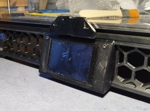
A front mount for MKS TS35 screen for the Voron Trident machine. It was designed as drop in replacement of Mini 12864 holder and has only one single printed part. The MKS TS35 is larger than the Mini 12864 one, so the panel is 4mm taller and slightly sloped. This should not be a problem neither for bottom panel sheet nor for doors. There are two versions: a 117 mm width which is default Voron Trident size a 122 mm width which help me to reduce gaps between front panel components. Please choose whichever option suits you best. The part should be printed with Voron recommended settings. Before installing the display, please remove two small supports near the bottom clip and check the size of the window cut (the display has a fairly tight fit). The display is secured with two M3 bolts/nut of suitable length (e.g. M3x8). -

Version 1.0.0
205 downloads
CatPaw is the ideal toolhead for Voron Zero series with Orbiter 2.0 Extruder. I developed this toolhead as I was unhappy with the existing options. The standard Voron Zero 0.2 toolhead does not provide as much cooling as I prefer, and certainly less than the StealthBurner toolhead. My design goals were also minimum loss of print volume and maximum compatibility with toolheads and options for probe and filament sensor. CATPAW: Uses Voron Zero 0.2 toolhead cartridges, so should work with all toolheads for voron Zero 0.2 (fan saver recommended) 2x 4010 Blowers, with StealthBurner duct layout for near arctic level part cooling (2x 4010 provides more air than StealthBurner toolhead) Almost no loss in print volume. X axis should be full width, loss off a millimeter or so on X if you print with your door closed. (Magnets on my door are strong enough, so the door closes again if the toolhead bumps into it, giving me the full 120x120 mm even when printing ABS Option to add the slideswipe Probe. I shortened the probe, but all other parts can be used from https://github.com/SaltyPaws/Voron_0.1and0.2mods/SlideSwipe or original repo (https://github.com/chestwood96/SlideSwipe) Option to add under extruder filament Sensor Carriages are provided for MGN7 and MGN9 X-axis rails. It is recommended to print the provided X carriage for the appropriate rail. In order to minimize toolhead height, I lowered the screw hole for the rear mounting screw. The CATPAW toolhead will work with the stock Voron Zero 0.2 Carriage, but the screw securing the X-carriage from the rear will not fit. https://github.com/SaltyPaws/CATPAW_toolhead/raw/main/images/PXL_20240101_224037977.jpg?raw=true BOM 2x SHCS (preferred) or BHSC M3x25 bolt 3x M3 nut 2x NeoPixel 1x 3010 hotend fan 2x 4010 Blower 6x3mm magnets for probe (optional) 6mm steel ball for filament sensor (optional) Omron D2F-L micro-switch with lever for filament sensor (optional) 2x M2x12 or self-tapping screw to secure micro-switch (optional) Installation Instructions Assembly should be done in the following order: Probe Solder wires to 6x3mm magnets. In order to prevent loss of magnetism, let the magnets cool against another 6x3 magnet. Press the magnets into the slots by pushing the toolhead down on a hard object. Use a large flat soldering tip at around 230C to push the magnets deeper into the slots, you want the magnets to stick out ~0.5 to 1 mm. Again, let the magnets cool down attached to other magnets to prevent loss of magnetism. Ensure wire to magnet path has very low resistance (less than 4 ohm). route wires out trough little side window. Seal hole with red gasket maker. NeoPixels Create a chain of 2 neopixels. You do not have a lot of space to hide excess cable, so make the wires between the neopixels as short as possible, while still allowing them to slide into the slots. Test the neopixels! It will be more rework to remove the hotend fan and part cooling fans later. Fans First install 3010 part cooling fan. Be very careful to only press the edges of the fan, the fan will break when pushing the center of the fan (ask me how I know...) Then proceed with installing the blower fans. Use a knife to cut the upper right hand side of the blower fan (looking back to front). This is required for routing the majority of the wires. I used superglue to keep the fan together as you will remove a fan closing latch. I accidentally cut int the fanbox, and sealed up the hole with red gasket maker. For details - see pictures below: https://github.com/SaltyPaws/CATPAW_toolhead/raw/main/images/PXL_20231225_175242278.jpg?raw=true https://github.com/SaltyPaws/CATPAW_toolhead/raw/main/images/PXL_20231225_175256608.jpg?raw=true https://github.com/SaltyPaws/CATPAW_toolhead/raw/main/images/PXL_20231225_175325632.jpg?raw=true Toolhead Cardridge Ensure the heater wires are installed pointing towards the right hand fan that has space for wire routing. Thermistor, probe and fan wires will fit on the other side (left hand side fan). Hold off on installing the zip-ties, these are best installed after the toolhead is installed on the carriage. Filament Sensor Solder wires to filament sensor (2 outer most legs). You may want to shorten the legs somewhat for an easier fit. Trim lever, so that lever does not extend past micro-switch body Install micro-switch and ball Test sensor Install Toolhead Carefully mount toolhead, ensuring that wires are not pinched, and belt is not rubbing on gantry. The bulk of the wires will go in the gap carved out on the right hand side fan, the other side will have sufficient space for probe and fan wires. Min Probe See installation instructions in orignal repo: https://github.com/chestwood96/SlideSwipe-
- 2
-
-
- orbiter 2.0
- orbiter
- (and 33 more)
-
Version 1.0.0
42 downloads
I couldn't find an elegant way to attach the Z-Chain with a aluminium AB drive upgrade, so i remixed a original spacer... I have the Alu AB Drive Set from Funssor -
Version 1.0.0
49 downloads
This Cable Bridge has been redesigned to fit a carbon or CNC aluminum XY joint where the screws are not flush with the top surface of the XY joint. This bridge also provides a little more distance from the cable chain. -
Version 2022.04.03
261 downloads
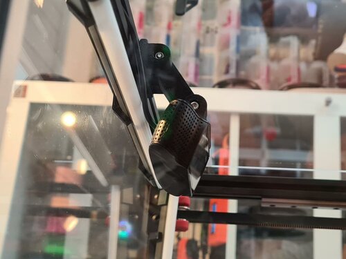
Important Notes Hello everyone, Here is my C920 camera mod, please follow the disassembly guide below to remove the current mount off the camera. Please keep the 4 bottom screws from the mount as you will need them for my mod. Instructions For Disassembly Found Here! This mod allows you to set 2 point position for your camera, BOM Qty Item 2 M3x40mm 1 M3x10mm 2 Nuts 1 M3 Hammerhead nut https://camo.githubusercontent.com/758a4b22a5c56662c568b7ffb24373659bc0266bcc721e882b16ef4f2bb51f16/68747470733a2f2f7777772e70617970616c6f626a656374732e636f6d2f656e5f55532f692f62746e2f62746e5f646f6e6174655f4c472e676966- 1 comment
-
- 4
-
-
- psychoshaft
- v1.8
- (and 2 more)
-
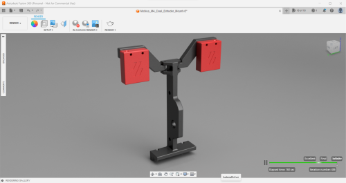
Version 2.0.0
61 downloads
Hey guys, So! I'm going dual (and triple) extrusion on my printers and didn't want to fuss with the ERCF for my smaller ones, so I bring to you the Mobius M4 dual extruder mount for the Voron 2.4 / Voron Trident. Tested as working - All fits together, all fits on to the voron, extruders attach easily. This is (kind of) a remix of the following: Elegoo Neptune 2-2S-2D Dual M4 Extruder Mount by mlee12382 | Download free STL model | Printables.com I got the original idea from the linked file above, I imported it into fusion 360 and sketched around it (getting rid of the unnecessary holes where they've obviously used tinkercad and the M4 baseplate. Instead of the silly (weak looking) cylinders that have been merged to some other blocks, I sketched out a stronger join and inserted the holes through that - also got rid of the stupid hole sizes that were used and made these 3.2mm in diameter for the M3 screws and 5.2 for the M5 screws - this means your screws should slide in nicely even if your settings are off. With the Filament Runout Sensor mounts, so far I have just copied the original, but again made the joints stronger and the holes a decent size - I'm not sure if this will work with the sensors I want to use so will report back later - the way these are designed means you can print them flat instead of upright, saving time! On top of this, I have added fillets to any stress points I considered to be weak - this should improve longevity of the mount. To mount it on to the printer I have just used the Voron spool holder mounting technique - it is designed to sit into the 2020 extrusion and grip over the top panel.