Search the Community
Showing results for tags 'orbiter 2.0'.
Found 5 results
-

Version 1.2.5
44,958 downloads
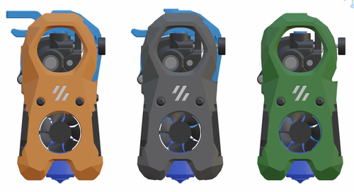
The Mini Stealth v2 toolhead is up on GitHub now. I will keep these files here as the new parts are not compatible with the v1.2.5 parts. I will support both versions in the comments here. I still need to create new assembly instructions but a lot of the steps are similar to what is described here. --------------------------------------------------------------------------- This toolhead scales down the body of the Stealthburner to a size which fits into a V0.1/V0.2. Fully assembled it weighs about 110 grams less than the original. It is designed around the Orbiter 2.0 extruder and has versions for the Phaetus Dragonfly, Dragon and Rapido HF hotends as well as versions for the Mosquito, the Revo Voron and the Creality Spider Pro hotends. It incorporates a status LED as well as two for print visibility. I have added new stretched versions that should fit the Rapido UHF, Dragon UHF and the VolcoMosq hotends. The Dragon UHF and Rapido UHF hotends can fit in the same shroud. The UHF hotends will reduce Z travel by 8.5mm and the VolcoMosq by 3mm. I cannot verify the fitment so if there are any issues please leave a comment. There are now two hex pattern inlays based on the design by 3DP-MAMSIH and a tutorial on how to apply them to the shroud. The negative body feature of Prusa/Super Slicer can also be used to create a crop-top version of the shroud as described at the end of the tutorial. The Mini Stealth uses a pair of 4010 blowers which produce more airflow than a 5015 blower while being notably less noisy and drawing less current. The depth of these fans do limit Y travel by 3mm on a V0.1 while the door is closed and tophat is on. The width of the main body at its base is also a very tight fit at the extremes of X travel. I have raised my tophat by 20mm which gives the cabling and filament tube plenty of room to breathe. The shroud fits a 3010 hotend fan or a 3007 fan by using a clip-in adapter. This Orbiter 2.0 Mini Stealth is a better fit than the Orbiter 1.5 Mini Stealth in a V2.4 or Trident as the motor no longer interferes with the path of the cable chain. There is a separate 'strain_relief' stl for use in the V0.1. There are also x-frame pieces that allow this Mini Stealth to be installed on a Switchwire. The nozzle is moved up by 3mm compared to the official Switchwire due to the stepper motor being so low on the Orbiter extruder but this also allows a BL-Touch to fit into the x-frame pieces. I have included a magnet mount and additional shroud .stl files to make this compatible with the ZeroClick mod. This toolhead also has versions that allow mounting a differential IR sensor. I have removed the mechanical Z endstop on my V0.1 and use the IR probe as an endstop and it has greatly simplified my homing sequence. There are additional x-frame pieces that allow mounting the Beacon3D probe, Euclid or Biqu MicroProbe for a V2.4, Trident or Switchwire. The included Blender file shows the entire assembly complete with screws and should answer most basic questions. Note on MGN-9 installation: The default 2mm x 10 plastic threading screw is too long for mounting the x-axis endstop. An M2 x 8 does the job fine. For mounting to the linear carriage use four M3 x 6 flat-head screws. Note: The MGN carriage shown is an MGN-9H, not the shorter MGN-9C used in the V0.1 mod. Preparation I recommend using a file to lightly remove any printing artifacts on the mating face of the shroud. Use a small file to smooth out the break-off edges of the LED PCB and make sure the LED pockets are clear of 'droopy bits' All three fans will need the wire retention piece clipped so the wires fit into the shroud channels easier. Differential IR Probe Installation The IR Probe needs to be screwed into place with two M2.5x8 FHCS before installing any of the fans, except with the VolcoMosq or UHF hotends where the probe needs to be glued on with CA glue. The Y-offset for this probe is 4mm in front of the nozzle and the X-offset is 32mm. I strongly recommend removing the 3-pin header and soldering wires directly to the probe PCB. When installed the wires will route out from the back of the IR probe cover to then join with the hotend and fan wires. I have included a cover to allow a connector at the probe but the wire management will be less than ideal.. Assembly Instructions After pressing the status LED diffuser into place, install the right part-cooling fan first by feeding the wires through the small hole at the bottom. Then feed the wires for the status LED and hotend fan through before starting to push the LED carrier into position. Carefully push the status LED carrier as far as it will go and press the fan into position while making sure not to pinch the part-cooling fan wires. Then press the remaining LEDs into their slots. (I measure out 35mm of wire to connect these LEDs together) Here is another view also showing where the hotend fan wires fit. Insert the second part-cooling fan and splice the wires together with the first fan. Install the hotend with at least two M2.5x6 screws (M3x6 for the Revo Voron). The heater cartridge should be installed away from the LEDs to avoid overheating them. (** don't forget the PTFE tube) Pre-assemble the extruder pieces before installing into the shroud. Use two M3x8 BHCS to install the Orbiter 2.0 extruder. It helps to have both screws in the Orbiter before putting it in place. Start the screw by the latch and then the blind screw should be easier to align. Gather all of the wires together with a zip-tie next to the base of the Orbiter latch and then use another zip-tie to secure the wires to the motor-bridge. Leave a little slack in the extruder wires. Install the strain_relief or cable_chain_mount with two M3x6/8 screws and the cable_door with a M3x10/12 screw. Close the cable door with a M3x6 BHCS and screw in the extruder tensioning thumb screw. Use two M3x40 BHCS to secure the toolhead to the x-carriage in a V0.1/V0.2. For installation in a Trident or V2.4 use two M3x50 BHCS. Happy Printing!- 559 comments
- 3 reviews
-
- 35
-

-

-

-
- orbiter 2.0
- v0.1
- (and 16 more)
-
Version 1.0.0
1,793 downloads
Hi All Here is my take on the Orbiter v2 and Filament sensor and mount for BTT EBB36. Could not have done this without the already existing excellent work form spacelab_2021. -
Version 1.0.0
4 downloads
I created this file, because the original Orbiter Sensor light guide does not hold the PTFE in place sufficiently to my taste. PC4-M10 connector for Orbiter Sensor. Print upside down, no suports needed. I used transparent ABS, but light colored ABS will also work. Use M10x1.25 tap to clean up threads Plug in and enjoy! -

Version 1.0.0
148 downloads
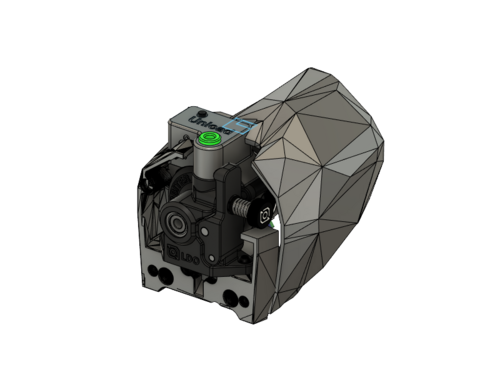
CatPaw is the ideal toolhead for Voron Zero series with Orbiter 2.0 Extruder. I developed this toolhead as I was unhappy with the existing options. The standard Voron Zero 0.2 toolhead does not provide as much cooling as I prefer, and certainly less than the StealthBurner toolhead. My design goals were also minimum loss of print volume and maximum compatibility with toolheads and options for probe and filament sensor. CATPAW: Uses Voron Zero 0.2 toolhead cartridges, so should work with all toolheads for voron Zero 0.2 (fan saver recommended) 2x 4010 Blowers, with StealthBurner duct layout for near arctic level part cooling (2x 4010 provides more air than StealthBurner toolhead) Almost no loss in print volume. X axis should be full width, loss off a millimeter or so on X if you print with your door closed. (Magnets on my door are strong enough, so the door closes again if the toolhead bumps into it, giving me the full 120x120 mm even when printing ABS Option to add the slideswipe Probe. I shortened the probe, but all other parts can be used from https://github.com/SaltyPaws/Voron_0.1and0.2mods/SlideSwipe or original repo (https://github.com/chestwood96/SlideSwipe) Option to add under extruder filament Sensor Carriages are provided for MGN7 and MGN9 X-axis rails. It is recommended to print the provided X carriage for the appropriate rail. In order to minimize toolhead height, I lowered the screw hole for the rear mounting screw. The CATPAW toolhead will work with the stock Voron Zero 0.2 Carriage, but the screw securing the X-carriage from the rear will not fit. https://github.com/SaltyPaws/CATPAW_toolhead/raw/main/images/PXL_20240101_224037977.jpg?raw=true BOM 2x SHCS (preferred) or BHSC M3x25 bolt 3x M3 nut 2x NeoPixel 1x 3010 hotend fan 2x 4010 Blower 6x3mm magnets for probe (optional) 6mm steel ball for filament sensor (optional) Omron D2F-L micro-switch with lever for filament sensor (optional) 2x M2x12 or self-tapping screw to secure micro-switch (optional) Installation Instructions Assembly should be done in the following order: Probe Solder wires to 6x3mm magnets. In order to prevent loss of magnetism, let the magnets cool against another 6x3 magnet. Press the magnets into the slots by pushing the toolhead down on a hard object. Use a large flat soldering tip at around 230C to push the magnets deeper into the slots, you want the magnets to stick out ~0.5 to 1 mm. Again, let the magnets cool down attached to other magnets to prevent loss of magnetism. Ensure wire to magnet path has very low resistance (less than 4 ohm). route wires out trough little side window. Seal hole with red gasket maker. NeoPixels Create a chain of 2 neopixels. You do not have a lot of space to hide excess cable, so make the wires between the neopixels as short as possible, while still allowing them to slide into the slots. Test the neopixels! It will be more rework to remove the hotend fan and part cooling fans later. Fans First install 3010 part cooling fan. Be very careful to only press the edges of the fan, the fan will break when pushing the center of the fan (ask me how I know...) Then proceed with installing the blower fans. Use a knife to cut the upper right hand side of the blower fan (looking back to front). This is required for routing the majority of the wires. I used superglue to keep the fan together as you will remove a fan closing latch. I accidentally cut int the fanbox, and sealed up the hole with red gasket maker. For details - see pictures below: https://github.com/SaltyPaws/CATPAW_toolhead/raw/main/images/PXL_20231225_175242278.jpg?raw=true https://github.com/SaltyPaws/CATPAW_toolhead/raw/main/images/PXL_20231225_175256608.jpg?raw=true https://github.com/SaltyPaws/CATPAW_toolhead/raw/main/images/PXL_20231225_175325632.jpg?raw=true Toolhead Cardridge Ensure the heater wires are installed pointing towards the right hand fan that has space for wire routing. Thermistor, probe and fan wires will fit on the other side (left hand side fan). Hold off on installing the zip-ties, these are best installed after the toolhead is installed on the carriage. Filament Sensor Solder wires to filament sensor (2 outer most legs). You may want to shorten the legs somewhat for an easier fit. Trim lever, so that lever does not extend past micro-switch body Install micro-switch and ball Test sensor Install Toolhead Carefully mount toolhead, ensuring that wires are not pinched, and belt is not rubbing on gantry. The bulk of the wires will go in the gap carved out on the right hand side fan, the other side will have sufficient space for probe and fan wires. Min Probe See installation instructions in orignal repo: https://github.com/chestwood96/SlideSwipe-
- 2
-
-
- orbiter 2.0
- orbiter
- (and 33 more)
-
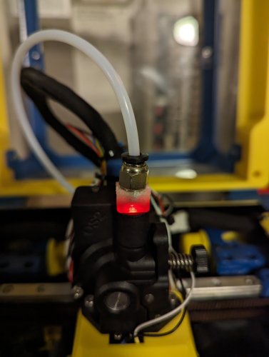
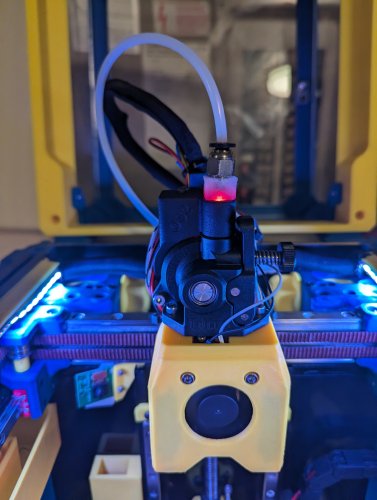
My Voron 2.4 running Klipper had been running great for a while but the afterburner assembly was starting to show weakness. I thought it was a good time for an upgrade so I installed a new Orbiter 2.0 with filament detector on my Voron 2.4 and the problems began...... witht he Orbiter 2.0 installed i have not been able to get my rotation distance anything like close to accurate. last print had massive over extrusion with lots of noise from the extruder. To statrt isolating the problem /as an experiment I ran 50mm (requested) filament through the extruder body only (no lower nozzle assempbly) and got about 250mm of filament instead. Fortunately the awful noise stopped. Ergo i think my initial problem is that the over extrusion i jsut discovered was overwhelming the nozzle and jamming. easy so far. On to the print config..... And incredible frustration as any and all changes to the print config file make no measurable difference in the amount of over feed. here is the code after a lot of trial and error and no change (i suspect there are a number of settings that i have turned off or on to see what if anything would happen- no change.). here is the code- ##################################################################### # Extruder ##################################################################### ## Connected to MOTOR_6 ## Heater - HE0 ## Thermistor - T0 [extruder] step_pin: PE2 dir_pin: PE3 enable_pin: !PD4 ## Update value below when you perform extruder calibration ## If you ask for 100mm of filament, but in reality it is 98mm: ## rotation_distance = <previous_rotation_distance> * <actual_extrude_distance> / 100 ## 22.6789511 is a good starting point #Bondtech 5mm Drive Gears AfterBurner ## 34.37086 for Bondtech 8mm gears (Galileo ## rotation_distance: 4.637 for Orbiter 2.0 rotation_distance: 4.637 ## Update Gear Ratio depending on your Extruder Type ## Use 50:17 for Afterburner/Clockwork (BMG Gear Ratio) ## Use 80:20 for M4, M3.1 # orbiter motor LDO-36STH20-1004AHG(XH) # gear_ratio: 7:1 microsteps: 16 full_steps_per_rotation: 200 #200 for 1.8 degree, 400 for 0.9 degree # max_extrude_only_distance: 500 # max_extrude_only_velocity: 120 # <- for orbiter motor LDO-36STH20-1004AHG(XH) # max_extrude_only_accel: 800 # <- for orbiter motor LDO-36STH20-1004AHG(XH) nozzle_diameter: 0.400 filament_diameter: 1.75 heater_pin: PA2 ## Validate the following thermistor type to make sure it is correct ## See https://www.klipper3d.org/Config_Reference.html#common-thermistors for additional options sensor_type: SliceEngineering 450 sensor_pin: PF4 min_temp: 10 max_temp: 270 max_power: 1.0 min_extrude_temp: 170 # control = pid # pid_kp = 26.213 # pid_ki = 1.304 # pid_kd = 131.721 ## Try to keep pressure_advance below 1.0 pressure_advance: 0.025 ## Default is 0.040, leave stock pressure_advance_smooth_time: 0.030 ## E0 on MOTOR6 ## Make sure to update below for your relevant driver (2208 or 2209) [tmc2209 extruder] uart_pin: PE1 interpolate: False run_current: 0.85 hold_current: 0.100 sense_resistor: 0.11 stealthchop_threshold: 0 # driver_TBL: 0 # driver_HEND: 6 # driver_HSTRT: 7 # driver_TOFF: 4 ###################################################################################################### ## I haven't made any changes above or below these lines so i the problem MAY be in here################################## ###################################################################################################### All of which leads me to my theory - incorrect wiring of the ldo-36st17-1004ahg to the tcm2209. Now i am very new to electronics and the instructions for wiring the Orbiter 2.0 to the V2.4 are yet to be found by me (if anybody has them, please share) so it would be an easy mistake. i feel like this is some sort of reversed polarity issue and leaves me with no idea where to begin with figuring this out. anybody got any ideas?