Search the Community
Showing results for tags 'canbus'.
Found 15 results
-
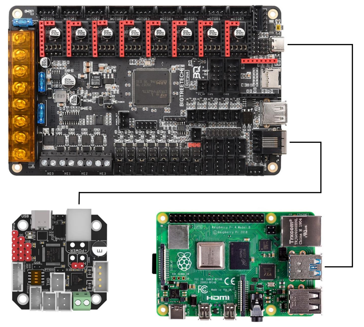
 I found this Canbus with CanBoot and Octopus excellent guide on Facebook, posted by TJ M. Wanted to share it with the community and make it easier to find! How to Use CAN Toolhead Boards Connected Directly to Octopus / Octopus Pro on CanBoot Klipper has a new CAN bus feature, the USB to CAN bus bridge communication for Octopus boards (and other compatible MCUs). This feature allows the Octopus boards (and other compatible MCUs) to act as a USB to CAN bus adapter. This replaces the need for an adapter like a Raspberry Pi CAN HAT, canable adapter, or the Bigtreetech U2C board. What is CanBoot? CanBoot is a custom bootloader loaded onto your Octopus and EBB board that allows users to update Klipper firmware over USB, UART, or CAN comms without physically having to access the board reset buttons or BOOT jumpers. It uses the same ‘make menuconfig’ setup to configure and compile firmware. CanBoot is NOT required to use the Klipper USB to CAN bus bridge comms. But I have not tested this comms feature separately. You Will Need the Following USB-A to USB-C cable Power supply for Octopus and EBB toolboard (i.e. printer) RJ11 or RJ12 telephone cable, crimped to connect EBB board to Octopus See wiring info at end of guide. Best to setup wiring before installing software. Raspberry Pi, or similar, with Klipper / Moonraker / UI installed and working Computer with following software: SSH terminal software, I use PuTTY or Windows CMD WinSCP, to transfer files between Raspberry Pi and computer I also use Windows CMD to do this STM32CubeProgrammer Download for your computer OS and install https://www.st.com/en/development-tools/stm32cubeprog.html#getsoftware High Level Instructions, for Understanding Install CanBoot on Raspberry Pi, flash firmware to boards Configure and compile CanBoot firmware for Octopus / Pro and EBB Flash CanBoot to boards using STM32CubeProgrammer and computer Setup boards for Klipper Octopus - Setup Klipper for USB to CAN bus bridge, with CAN comms to EBB EBB - Setup Klipper for CAN comms Find serial device for Octopus / Pro on Raspberry Pi Flash Klipper to Octopus / Pro with CanBoot serial command Setup can0 network on Raspberry Pi, power cycle printer Find CAN uuid for Boards a. Connect EBB to Octopus / Pro, power cycle printer Flash Klipper to EBB board with CanBoot CAN command Printer Config Update and General Tips How to Use CanBoot to update boards, Tips Okay, enough talking! Let’s get started! (download the FULL 25 Page guide below! How to Use CAN Toolhead Boards Connected Directly to Octopus.pdf
-
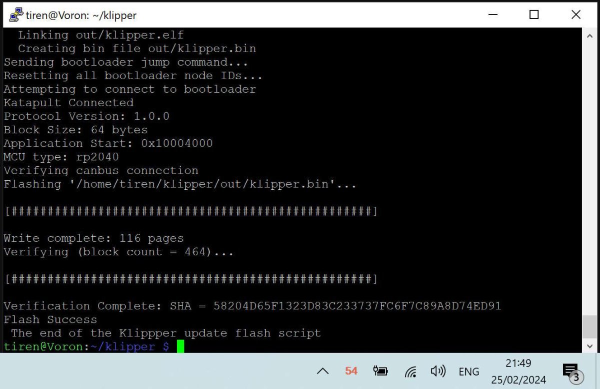
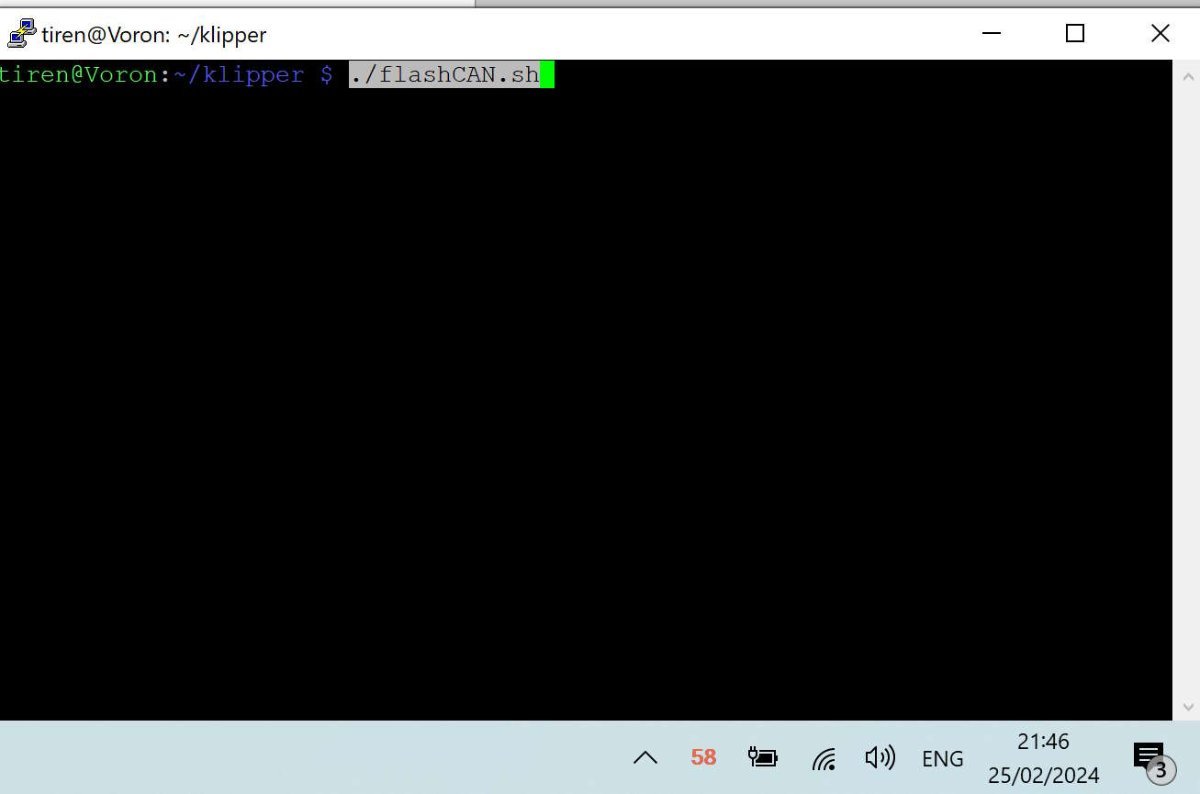
I have been converting my Voron 2.4 from many-cables-to-the-toolhead, into a single can-cable (4 wires) system. Even though I saw here that many people really did not like the CAN bus on their printers, mainly because it was new and unknown. The problem of the web is and always has been, that you never hear the 'satisfied' people. Only the very unhappy, the very happy and the sales-people. I hope this script will make it easier for some to make the step to the 'new'. I have never been afraid of new things. The problem was finding a way to find the set up I needed. From one came the other and what happened was, that I was able to combine information from a few sites / github pages I visited, and was able to write a simple script that did all the work. Actually very much like every software / game in the pre-windows 95 era, came with its own 'set-up' disk, with config.bat / setup.bat files. As long as I do not have a Klipper '95, I think this script will do for me. I tested it, and it takes 3 to 4 minutes to update the mainboard and toolhead PCB. Faster than 5 minutes I heard mentioned before. I will paste the script down here, with all the comments and the instructions. and attach as an attachment also. If there is a better way, let me know. It is information gathered mainly from Esoterical's guide. You will need information from this guide to set up your own script. -------------------------------- SCRIPT flashCAN.sh ------------------------------------------------------------------ #!/bin/bash ### without the extensive documentation and work of Esoterical, this would never have been possible. ### Besides Esoterical, this script builds standing on shoulders of: ### Eddie the engineer. https://www.youtube.com/watch?v=1P4UrJxChL8 Thanks! ### cruiten https://github.com/cruiten/Voron-Related/blob/main/CANbus/Documentation/SB2040_CAN/flash_klipper_script.md Thanks! ### uses # https://docs.kernel.org/kbuild/kconfig.html KCONFIG_CONFIG is used to define an alternative config file... ### to define a separate config file for mainboard (eg Octopus) or for a canbus toolhead PCB. For both cases one for katapult and one for klipper. ### the make menuconfig commands use the Esoterical github provided 'mainboard/common_hardware and toolhead_flashing/common_hardware maps provided image options ### https://canbus.esoterical.online/mainboard_flashing/common_hardware.html ### https://canbus.esoterical.online/toolhead_flashing/common_hardware.html ### HOW TO USE: Follow Esotericals guide, starting at the begin: https://canbus.esoterical.online/Getting_Started.html ### it will lead you through setting up a can network on your Klipper running os. ### I skipped the part about dedicated can_boards, and continued with the klipper USB 2 CAN bridge provided by my mainboard: https://canbus.esoterical.online/mainboard_flashing ### will go through flashing your mainboard for CAN. go through EVERY step. and DO NOT skip the STOP warnings. This will install katapult. USB2CANbus bridge ### afterwards it will assist you through flashing your toolhead: https://canbus.esoterical.online/toolhead_flashing ### like with the mainboard, you will install katapult and then the klipper can interface on it. ### when you are finished, you get advise on how to finish it: https://canbus.esoterical.online/Final_Steps.html ## You are happy and you see an update from Klipper in mainsail. You push the update button and your whole system is unaccessable, ## because your hardware is no more up to date with the latest klipper... ## in that case you can follow the "so you clicked the update button???" : https://canbus.esoterical.online/Updating.html ## because I did not want to go through the same repetitive steps, I made this below script. ## If I did not think this would be faster than the 5 minute update teamfdm.com @mvdveer needs to update his printers, I would have kept it to myself. ## -------------------------------------------------------- HOW TO USE ----------------------------------------------------------- ## save this document and copy to your klipper system into the /klipper directory. ## give it a name (eg. flashCAN.sh) ## ssh into your system. go to your klipper directory and run the command: sudo chmod +x flashCAN.sh ## now you can run the script by typing the following command in ssh ## ~/klipper/flashCAN.sh ## make sure to fill in your OWN values for ## - usb-katapult_your_mainboard_usb_id ## - yourmainboarduuid ## - yourtoolheaduuid # these are values for me! # yourmainboardUUID=403544310df5 # katapult_your_mainboard_usb_id = usb-katapult_stm32f446xx_200035000851313133353932-if00 # yourtoolheaduuid =21c36fa97c26 ## while installing CAN the first time, note your usb-katapult-mainboard-usb-id, mainboard UUID, toolhead UUID. ## or if you have a functioning CAN network, run ~/klippy-env/bin/python ~/klipper/scripts/canbus_query.py can0 to see a list of installed CAN devices. ## the UUID for mainboard and toolhead you need to put in your printer.cfg file, so you can retrieve it from there. ## But the USB serial ID you have to obtain after you put the mainboard into katapult boot flash mode (STEP 2 A below). ## after the command python3 ~/katapult/scripts/flashtool.py -i can0 -u yourmainboarduuid -r ## you will need to type: "ls /dev/serial/by-id" and it will give you your USB serial ID. ## once you have run through this script, comment out (put a # in front of the line) the line which has the "make menuconfig" in it. ## and the next time you have a klipper update that breaks your CAN, all you have to do, is to run this script once. #-------------------------------------FINAL WORDS-------------------------------------------------- # this script is for me and my set up. # HARDWARE # Raspberry Pi 4B, 8mb # Voron 2.4, 350 # Octopus Pro mainboard # SB2209 (RP2040) Big Tree Tech 2 part Toolhead PCB # Cartographer 3D Eddy Probe in CAN mode # with built in accelerometer / resonance tester # The Octopus functions as a CAN bridge. Cartographer 3D is connected to The SB2209 (RP2040). # The CAN bus is terminated at the Cartographer 3D probe. # SOFTWARE: # OS: Raspbian GNU/Linux 11 (bullseye) # Distro: MainsailOS 1.2.1 (bullseye) # klipper: v0.12.0-114-ga77d0790 # if you are not using this script on my system then anything can happen which I am not responsible for. echo "STEP 1 - UPDATE KATAPULT FROM GIT if needed" test -e ~/katapult && (cd ~/katapult && git pull) || (cd ~ && git clone https://github.com/Arksine/katapult) ; cd ~ echo "STEP 2a - FLASH MAINBOARD KATAPULT so we can flash it easily" cd ~/katapult make clean KCONFIG_CONFIG=config.mainboardKatapult # cleans old files make menuconfig KCONFIG_CONFIG=config.mainboardKatapult # this can be commented out for automation AFTER you have filled out correct fields for your card. or leave it in to have some control make KCONFIG_CONFIG=config.mainboardKatapult # this creates a deploy.bin python3 ~/katapult/scripts/flashtool.py -i can0 -u yourmainboarduuid -r # puts mainboard in katapult flash mode python3 ~/katapult/scripts/flashtool.py -f ~/katapult/out/deployer.bin -d /dev/serial/by-id/usb-katapult_your_mainboard_usb_id # flashes katapult to mainboard echo "STEP 2b - FLASH MAINBOARD so it works as a CAN BRIDGE, over KATAPULT" cd ~/klipper make clean KCONFIG_CONFIG=config.mainboardUSB2CANbb # cleans old files make menuconfig KCONFIG_CONFIG=config.mainboardUSB2CANbb # configuration for klipper-U2CBB. comment this line for automation make KCONFIG_CONFIG=config.mainboardUSB2CANbb # this creates klipper.bin sudo service klipper stop # mainboard still in katapult forced flash mode. so feel free to flash klipper can bridge on it! python3 ~/katapult/scripts/flashtool.py -f ~/klipper/out/klipper.bin -d /dev/serial/by-id/usb-katapult_yourmainboardusbid # flashes klipper-U2CBB to MAINBOARD sudo service klipper start echo "STEP 3a UPDATE TOOLHEAD KATAPULT so we can flash it easily" cd ~/katapult make clean KCONFIG_CONFIG=config.toolheadKatapult # clean old files make menuconfig KCONFIG_CONFIG=config.toolheadKatapult # comment out for full automation after once filled out! make KCONFIG_CONFIG=config.toolheadKatapult # build katapult deployer.bin python3 ~/katapult/scripts/flashtool.py -i can0 -u yourtoolheaduuid -r # put toolhead board into katapult flash mode python3 ~/katapult/scripts/flashtool.py -i can0 -u yourtoolheaduuid -f ~/katapult/out/deployer.bin # flash the katapult binary echo "STEP 3b UPDATING TOOLHEAD KLIPPER over KATAPULT" cd ~/klipper make clean KCONFIG_CONFIG=config.toolheadKlipper make menuconfig KCONFIG_CONFIG=config.toolheadKlipper make KCONFIG_CONFIG=config.toolheadKlipper sudo service klipper stop python3 ~/katapult/scripts/flashtool.py -i can0 -u yourtoolheaduuid -f ~/klipper/out/klipper.bin sudo service klipper start echo " The Klippper update flash script has finished. Hopefully all is working again :-)" flashCAN.sh
-

Version 2
2,573 downloads
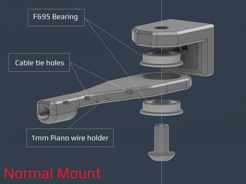
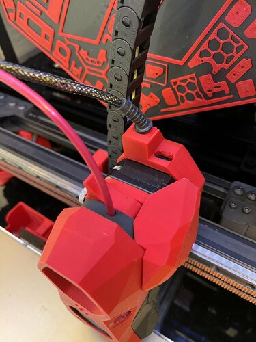
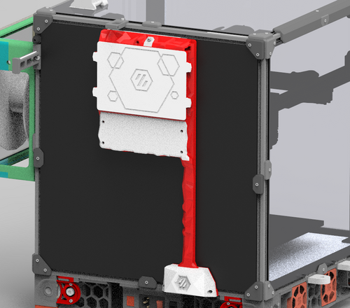
V2- PTFE bowden tube guide and CANBUS wire support I've made some adjustment after some feedback from the community. Changes made over V1: Added a option to have F695 bearings incorporated Enlarged the tube opening Added cable/zip tie openings Added spot for 1mm piano wire if needed. Recommended print settings: Voron print settings (4 walls, 40% infill and 5 top and bottom layers) Turn off thin walls Bridge setting: keep only bridges (watch out for bridging for cable tie holes) 0.2mm layers and 0.2mm first layer No need to adjust for ABS shrinkage Required Hardware: M3x8 Bolt and M3 T-nut M5 bolt to suit option. Optional M5 nut if you can fit it with the bearing option. V1 - PTFE bowden tube guide and CANBUS wire support This is can found inside the zip files and of the initial release Required Hardware: M3x8 Bolt and M3 T-nut M5x10 Bolt or a M5x8/12 Optional 4mm drill bit for cleaning out bowden tube path About In my 350 build the PTFE tube kept getting caught so I made this arm to keep it up. The shorter arm works better so I recommend using it instead The setup has also been used by a few user to support their CANBUS wires (zip tied to the reverse bowden) Install Drill out bowden guide with 4mm drill bit for a perfect fit (optional) Bolt mount to rear frame with M3x8 and tnut putting the lip at the top Screw arm on with M5x10 (I used a M5x8mm and it works fine) into the plastic allowing the arm to still be able to swivel- 3 comments
- 1 review
-
- 15
-

-
- canbus
- galvanicglaze
- (and 3 more)
-

Version 1.0.0
205 downloads
CatPaw is the ideal toolhead for Voron Zero series with Orbiter 2.0 Extruder. I developed this toolhead as I was unhappy with the existing options. The standard Voron Zero 0.2 toolhead does not provide as much cooling as I prefer, and certainly less than the StealthBurner toolhead. My design goals were also minimum loss of print volume and maximum compatibility with toolheads and options for probe and filament sensor. CATPAW: Uses Voron Zero 0.2 toolhead cartridges, so should work with all toolheads for voron Zero 0.2 (fan saver recommended) 2x 4010 Blowers, with StealthBurner duct layout for near arctic level part cooling (2x 4010 provides more air than StealthBurner toolhead) Almost no loss in print volume. X axis should be full width, loss off a millimeter or so on X if you print with your door closed. (Magnets on my door are strong enough, so the door closes again if the toolhead bumps into it, giving me the full 120x120 mm even when printing ABS Option to add the slideswipe Probe. I shortened the probe, but all other parts can be used from https://github.com/SaltyPaws/Voron_0.1and0.2mods/SlideSwipe or original repo (https://github.com/chestwood96/SlideSwipe) Option to add under extruder filament Sensor Carriages are provided for MGN7 and MGN9 X-axis rails. It is recommended to print the provided X carriage for the appropriate rail. In order to minimize toolhead height, I lowered the screw hole for the rear mounting screw. The CATPAW toolhead will work with the stock Voron Zero 0.2 Carriage, but the screw securing the X-carriage from the rear will not fit. https://github.com/SaltyPaws/CATPAW_toolhead/raw/main/images/PXL_20240101_224037977.jpg?raw=true BOM 2x SHCS (preferred) or BHSC M3x25 bolt 3x M3 nut 2x NeoPixel 1x 3010 hotend fan 2x 4010 Blower 6x3mm magnets for probe (optional) 6mm steel ball for filament sensor (optional) Omron D2F-L micro-switch with lever for filament sensor (optional) 2x M2x12 or self-tapping screw to secure micro-switch (optional) Installation Instructions Assembly should be done in the following order: Probe Solder wires to 6x3mm magnets. In order to prevent loss of magnetism, let the magnets cool against another 6x3 magnet. Press the magnets into the slots by pushing the toolhead down on a hard object. Use a large flat soldering tip at around 230C to push the magnets deeper into the slots, you want the magnets to stick out ~0.5 to 1 mm. Again, let the magnets cool down attached to other magnets to prevent loss of magnetism. Ensure wire to magnet path has very low resistance (less than 4 ohm). route wires out trough little side window. Seal hole with red gasket maker. NeoPixels Create a chain of 2 neopixels. You do not have a lot of space to hide excess cable, so make the wires between the neopixels as short as possible, while still allowing them to slide into the slots. Test the neopixels! It will be more rework to remove the hotend fan and part cooling fans later. Fans First install 3010 part cooling fan. Be very careful to only press the edges of the fan, the fan will break when pushing the center of the fan (ask me how I know...) Then proceed with installing the blower fans. Use a knife to cut the upper right hand side of the blower fan (looking back to front). This is required for routing the majority of the wires. I used superglue to keep the fan together as you will remove a fan closing latch. I accidentally cut int the fanbox, and sealed up the hole with red gasket maker. For details - see pictures below: https://github.com/SaltyPaws/CATPAW_toolhead/raw/main/images/PXL_20231225_175242278.jpg?raw=true https://github.com/SaltyPaws/CATPAW_toolhead/raw/main/images/PXL_20231225_175256608.jpg?raw=true https://github.com/SaltyPaws/CATPAW_toolhead/raw/main/images/PXL_20231225_175325632.jpg?raw=true Toolhead Cardridge Ensure the heater wires are installed pointing towards the right hand fan that has space for wire routing. Thermistor, probe and fan wires will fit on the other side (left hand side fan). Hold off on installing the zip-ties, these are best installed after the toolhead is installed on the carriage. Filament Sensor Solder wires to filament sensor (2 outer most legs). You may want to shorten the legs somewhat for an easier fit. Trim lever, so that lever does not extend past micro-switch body Install micro-switch and ball Test sensor Install Toolhead Carefully mount toolhead, ensuring that wires are not pinched, and belt is not rubbing on gantry. The bulk of the wires will go in the gap carved out on the right hand side fan, the other side will have sufficient space for probe and fan wires. Min Probe See installation instructions in orignal repo: https://github.com/chestwood96/SlideSwipe-
- 2
-
-
- orbiter 2.0
- orbiter
- (and 33 more)
-
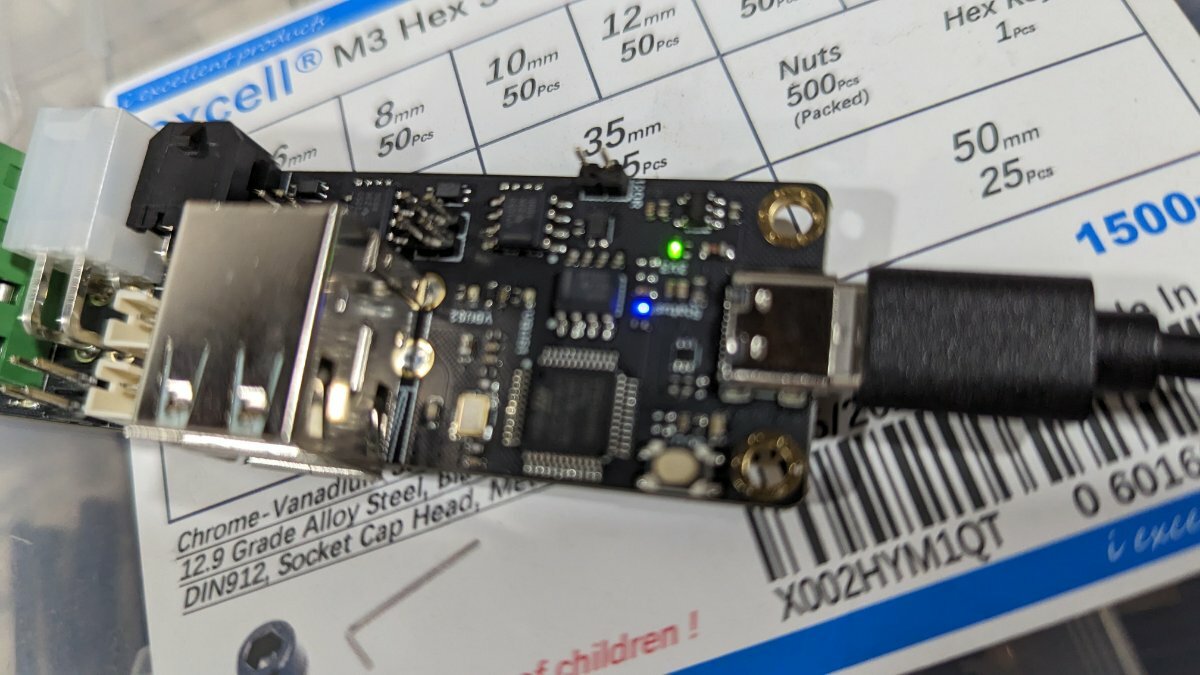
I have Can Bus up and running (sort of). I've installed all software and updated printer.cfg. When I start my machine, things look promising. I get a klipper blue screen with the message: "Printer is not ready. The klippy host software is attempting to connect". But then Klipper shuts down and reports either "Lost communication with MCU 'Can0'." or "mcu 'Can0': Unable to connect". I thought maybe I had Can Hi and Can Lo reversed or maybe a bad cable (or bad crimp job by yours truly). But when I measured the voltage relative to ground at my U2C, I get 2.6 ish for Can Hi (that's fine), but only 1.35 for Can Lo. Is this to be expected? I've read that Can Lo should be between 1.5 and 2.5. So I'm thinking I must have a hardware issue. Has anyone else encountered this?
-
Hi everyone ! I got a Voron 2.4 controlled with a RP3 and an Octopus board. I want to upgrade it with a SB2040 from Mellow Fly, connected directly to the Octopus's canbus port. (Use a U2C or a canhat would be too easy). I followed the FDMTeam's tutorial : how-to-use-can-toolhead-boards-connected-directly-to-octopus-octopus-pro-on-canboot I also found that the CanBoot project seems compatible with the RP2040 mcu : Issue to integrate the RP2040 to the canboot And I also complete voids with the flash configuration recommended by Mellow Fly : SB2040 Flashing tutorial But at the moment, Klipper can't connect to the octopus and the SB2040 seems unflashed (the blue LED which mean "firmware's running" remains off). Sorry for the long post but, if it can help someone else, I have to detail everything. I did the following steps : Make a CanBoot bootloader for the Octopus Make a CanBoot bootloader for the SB2040 Flash the Octopus with STM32Cube Programmer and the CanBoot bootloader Flash the SB2040 from the Raspberry PI and the Canboot bootloader Make a Klipper bootloader for the Octopus Make a Klipper bootloader for the SB2040 Flash the Octopus with the Raspberry PI and the Klipper bootloader Flash the SB2040 throught the Octopus CanBus with the Klipper Bootloader Then I cried The can0 interface is still setup (ifconfig), I got my two can_uuid : [mcu] canbus_uuid: 3f56a5b6c36c ; [mcu SB2040] canbus_uuid: 2d70e57a001c But after I flashed the SB2040 through the canbus, his can_uuid disapeared. Of course, this probably comes from the fact that I can't use STM32Cube Programmer to make a "dual flash" ? I didn't truly understand the purpose of using STM32 Cube in that case. I replaced the [mcu] section of the printer.cfg file with : [mcu] canbus_uuid: 3f56a5b6c36c [mcu SB2040] canbus_uuid: 2d70e57a001c And the raspberry can't connect to the Octopus board. Klipper say : "mcu not available, try later". Not a surprise if Klipper is looking for the SB2040 mcu ! So, what did I miss ? Why after two flashs the SB2040 didn't have a firmware working ? Is there a software equivalent to STM32Cube to use with the RP2040 ? Thank you for your help. I know that the Canboot project is very young, and I'm looking for troubles, but I hope that it will also help other peoples who face the same problem.
-
Hello, my first topic here, hope to do the right things. Did anyone run into the Voron Stealhtburner leds not working with the Sb2040 in can bus mode? I have everything configured correctly, all the GPio in the right place, all working but the leds.... Very frustrating! The motherboard is the new Octopus Max EZ V1.0 without the UC2, tested the led with the connector on the board, all working, connected another CanBus board to the same motherboard(a BigTreetech EBB SB2240_2209 CAN v1.0) and working 100%. Was wondering if someone have solved this mistery. Cheers.
-
Hi, I installed Can on the SB2040, everything reports correctly except for my TAP : The LED on the tap board is red when down and blue when up. So no issues there. I soldered the opto-TAP board for 5V and had it originally installed on the 3-pin connector with the 5V and gpio28 I later found out that's not the way to do it and moved signal and ground to gpio25, leaving the 5V as is. Since it's not working anymore I wondered : did I fry my SB2040 ?
-
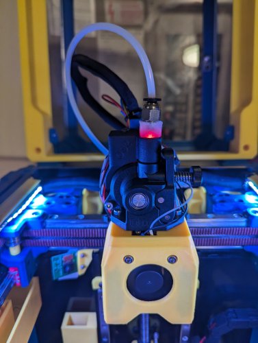
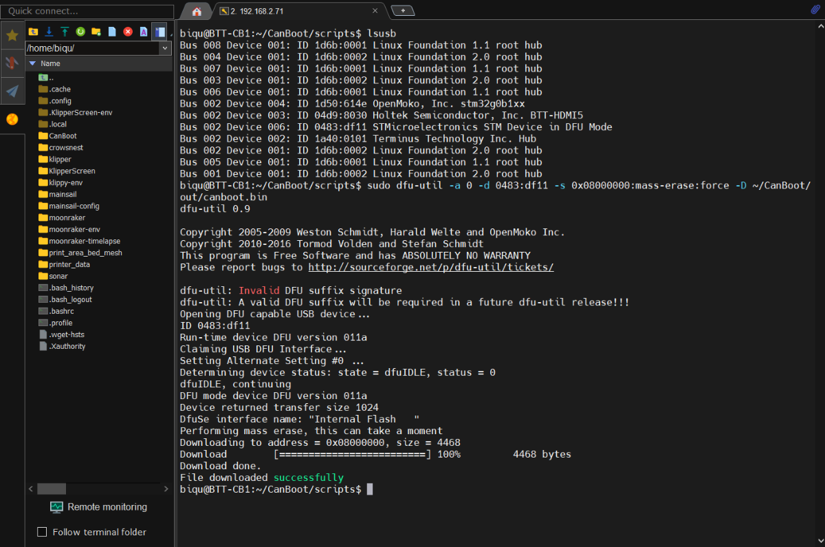
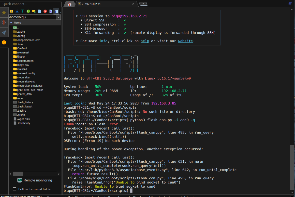
Sadly, this upgrade has been a night mare, everything that could go wrong has gone wrong. First, I realized that the CanBus board won't fit into the Steathbuners front piece, fine get the cutter out and modify the piece to make it fit.. can't print it now since I just ripped out all the cables. Installed the Rapido hot end in, the newly printed bottom pieces yay a win. Solder the pre crimped wire to the temp sensor. next redo all the chains, reroute all the other wire and the CanBus wire, rezip all the wires. The connector for the tap I cut the wrong end off, I'm like ok I will just re crimp it, oh look at of the 10 different JST connectors I have, I don't have this one. so, I have to magically hold in the wrong one and hope it makes a connection... Checking the toolhead for the Tap and its wobbling and the more I move the more it wobbles. I think my Chaotic Tap I got was a lemon, I didn't even get to print it was already wobbling from side to side the screws came loose for the Rail, I took it a part and retightened those screws and added lock tight. I put it all back together move the Tool head around Yay it seem to be better, aOh! I just realized the end stop won't work whit the chaotic tap, and realize I need to add a switch to the tool head body Great! Take it all apart again... sigh this feels like it the 4th time doing this... I get the switch in solder shrink tube wire and crimps, plug it.. screw it in and one of the screws instantly stripes sigh, rebuild the toolhead... Finally it was done on to flashing the board, everything seams good get through the first few parts all's good then I get to put the jumper on plug the cable in. cd ~/CanBoot/scripts python3 flash_can.py -i can0 -q and I can't seem to get past this part.. I can't move on because it won't give me the ID to flash the next part I gone over all the step like four times still can't get past this part... and I not sure what to do I have been working on this for the last few days, and I want to cry... Voron 2.4 Formbot kit, Manta MP8/CB1, BTT EB2209 Canbus, Chaoticlabs Tap, LGX Lite Extruder, Rapido Hotend, t...
-
Version 1.0.0
462 downloads
ebb42 mount for cw1 nema17 pancake with umbilical strain relief Decided to go to canbus umbilical for my stealthburner on cw1 and remove both x and y cable chains. As the ebb42 is a new product there had been no mounts that have been released at that time so i came up with this design. The mount sits comfortably on the rear of my extruder nema17 pancake motor and spaces the ebb42 nicely away from the rear of the motor, the m3 motor screws i have are slightly to long so i used spacers on top of the ebb42 to counteract this, also i used a cable strain relief to protect the 4 wires to the ebb42 which the dimentions are 5mm hole, 28mm length, diameter 11.8mm, slot diameter 7.55mm x2.1mm which goes into a little slide in wedge to hold into place and also used expandable braided sleeving size 3-9mm which protects the wires and sits nice and snug in the strain relief. i also modified the original stealthburner cw1 pcb cover by Demosth to fit with this mount (https://www.teamfdm.com/files/file/535-stealthburner-cw1-pcb-cover).- 10 comments
-
- 6
-
-
- stealthburner
- ebb42
- (and 3 more)
-
Trying to get canbus set up on Klipper and the BTT Canbus U2Cv2.1 and EBB36 boards. Started trying to follow this guide "YES!! You CANBus Setup." on Youtube but didn't get pass the flashing of the board from canibale.io --- said it flashed but when I power cycle the blue light stays on where it says the blue light should go off. I then tried following TeachingTechs guide "Klipper CAN bus guide for Bigtreetech U2C and EBB boards" and got the board flashed but then after power cycle the blue light remains on. Anyone here experience the same or know another guide or how to troubleshoot so I can move on in the setup process?
-
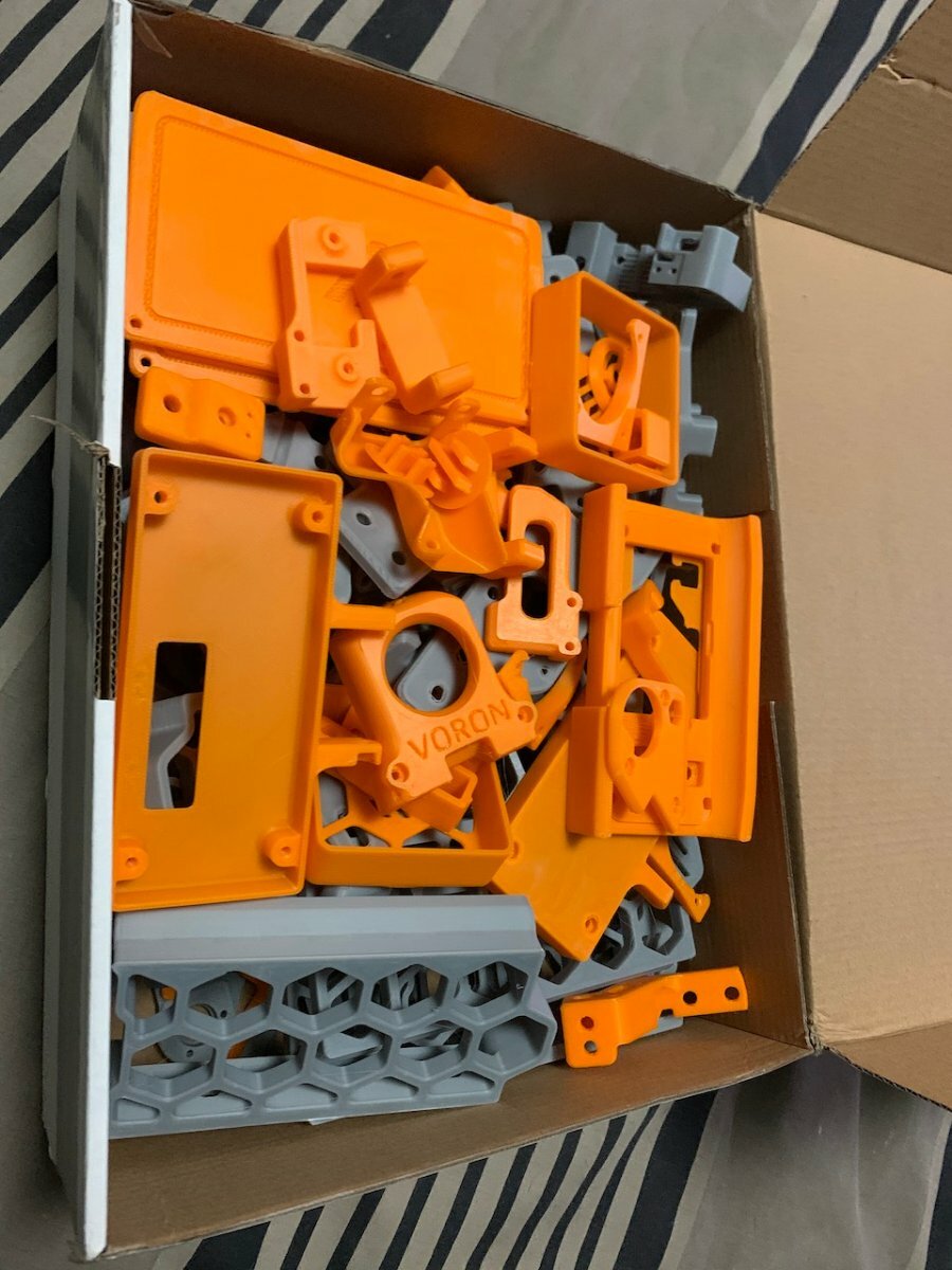
So my V2.4R0 was build with PIF parts from Germany (Australia does not have a PIF supplier) The built was bases on a LDO frame and Magic Phoenix parts. The mistake I made was not to make sure I could purchase the filament used for the accent, so I plan to switch colour. Serial Request Link The current build has a ABBN and a SHT42 CANBus board, but is still using the cable chains. As of right now the CANBus power cable has a break at the XY join on the right, meaning the machine stops all the time. With the broken wire a friend printed the X Carriage parts below for me while I was getting my V0 up to scratch. While building the X Carriage below I put a bolt in which was too long causing the white spot in the image. I'll reprint this once the machine is running again. I plan to upgrade to a MGN12 X, a Stealthburner, GE5C Z Mount, Voron Tap, Rama's Front Idlers, Orbiter V2 (initially but switching to Vz-Hextrudort-Low Extruder) and a SHT36V2. I'm not sure about is the X rail, I have the original aluminium, 20x20 machined aluminium tube, a carbon 20x20 tube and X/Y backers but not sure what combo I should select. So as you can see, I have a number of decisions to make. I need to get these upgrades done ASAP, as I want to start building my Trident.
-
Hi All So I've been planning to build a Trident for the last year and I now have all the non-printed parts. I bought some from via BOM links or comparable sources and eventually purchased a partial Magic Phoenix kit to fill-out parts I was missing. I printed the parts in the image around 10 months ago, so some of the parts are out of date. I'm also not 100% sure about the colour. This is a ABS filament available in Australia from a company called 3dFillies. I have some Fillamentum ASA Extrafill in traffic red and black which I could use instead. Comments?
-

Version 29.12.22
1,073 downloads
Burst from Discord Voron asked my if I can do an update of my old "HEPA + activated carbon Air filter mod" for his new machine: he wanted wiring for CanBus and ERCF I made it and added some "stealth" to it. Work in progress... This is based on Fanny Pack Air Filter. I dont know who made it originally.- 10 comments
-
- 17
-
-

-
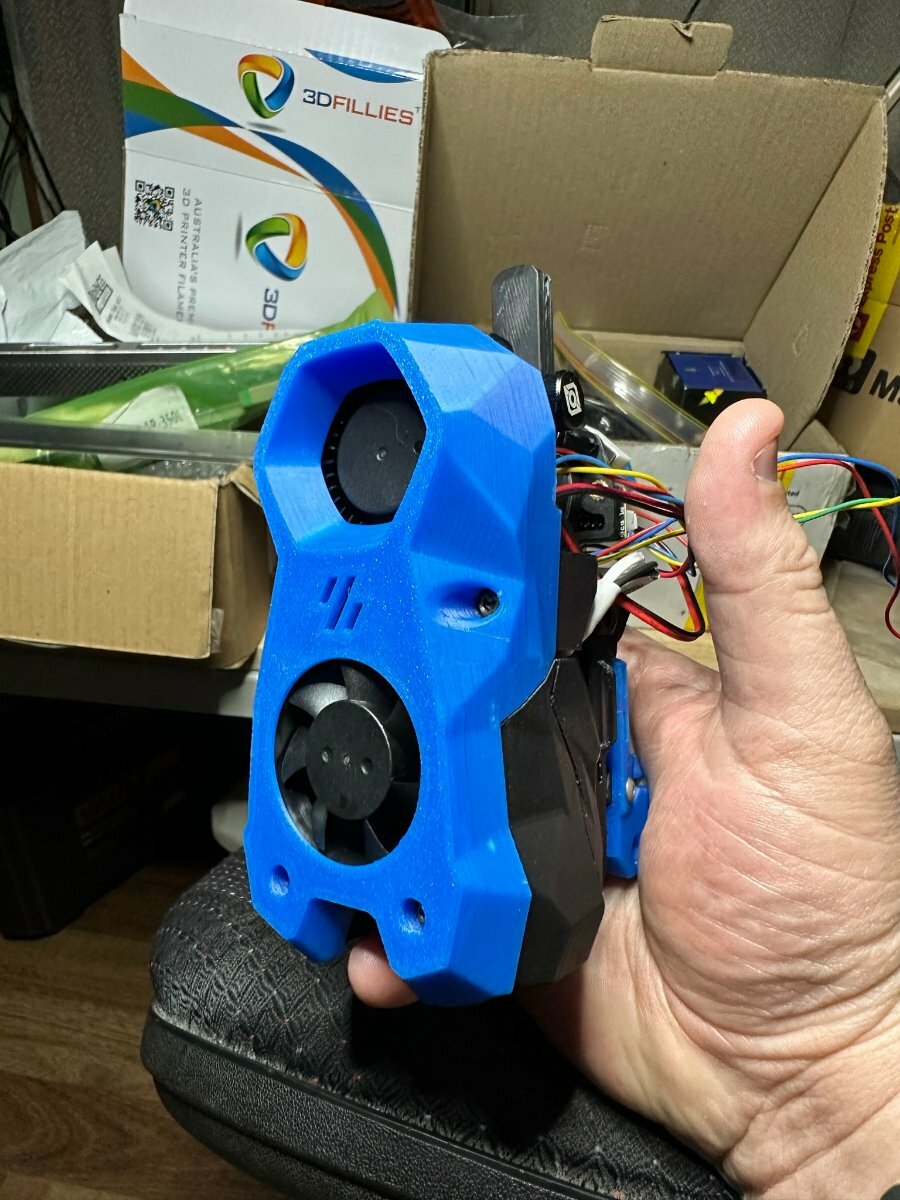
Hello, I just upgraded my Voron 2.4 with the U2C canbus interface and the EBB42 Canbus board. I need to get theCanbus speed up to 500000 to able able to use the onboard accelerometer for Klipper input shaping. Can anyone provide clear instructions how to build this firmware for the U2C? The Candlelight github page does not give enough details for me. A procompiled firmware for U2C at 500K would also be great. I designed a mount for the EBB42 for the Afterburner printhead. It can be found here:https://www.thingiverse.com/thing:5559591 There is another mount available on Thingiverse, but that created a bad interference with the drag chain. It was also sticking out to much, causing interference with the gantry drag chain while homing.