-
TeamFDM.com is an UNOFFICIAL companion site for the DIY Voron 3D printer community. For official docs and final source of truth, visit the Official Voron Discord or the Voron Github
Printable Voron User Mods
Voron User Mods, or "UserMods", are a collection of community created and Team FDM curated modification for Voron Printers. All of these mods are available on the VoronUsers Github repo and unless otherwise specified follow the Voron communities GPL3.0 Licensing. Use any Mods at your own risk, if you make modification please share them on the VoronUsers repo.
Mod Authors: Have a Voron mod? Upload it at TeamFDM.com and let us know you're the author. We will ensure you can update and curate your files for more feedback! Please include tags for what Voron, or extruder your mod is compatible with.
660 files
-

Trident Internal Spool Holder
Important Note:
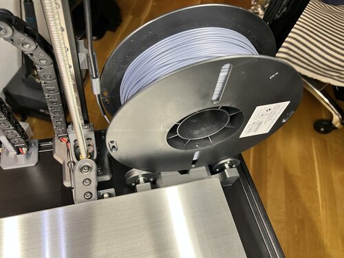
This mod works on Trident 300 and 350 builds ONLY. 250 build simply has no space needed to accomodate the holder and the spool. Sliding 8mm linear guides allows for adjustable spool width. Supported spool size is 200mm in diameter and up to max 75mm wide, typical for spools up to 1kg - 1.2kg.
Changelog
08.05.2022. Initial Release
20.05.2022. Added new PTFE guide with tilted opening that guides the PTFE slightly to the left to prevent sharp bends. Just one lower guide is recommended now with this new top guide.
Why?
Over the years i've been getting nicer prints and almost 100% eliminated wet filament ooze by placing the filament spool inside of enclosed chamber. Since my printers work almost 24/7, chambers are always hot enough to keep the filament dry and produce perfect prints.
Print Setup
All parts are printed without supports. Recommended material is ABS/ASA. Recommended perimeter count is 4 and 5 top/bottom layers with infil from 30% . All parts in STL already have correct orientation, just import and print.
STL File naming:
...x2.stl simply means you need to print 2 parts BOM
8x F688zz Flange Radial Ball Bearing 8 x 16mm 2x 8x100mm linear guide 12x M3x4mm countersunk screws (M3x6 BHCS or SHCS screws can be used as well) 18x M3x4x5 Brass Heat Inserts 2x M5x16mm 2x M5x10mm 4x M5 T-Nut (Regular or Hammerhead) 6x M3x8mm Images
988 downloads
-
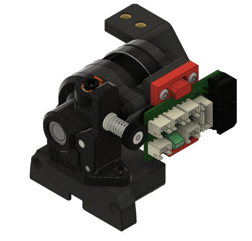
Lgx Lite Side Can
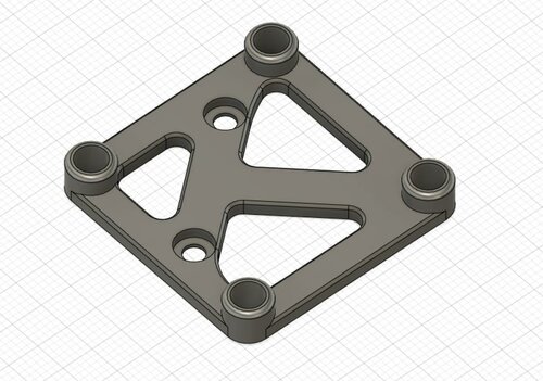
LGX Lite CAN Side Mount (Huvud/SHT42)
Side mount for CAN toolhead boards with NEMA 17 sizes such as Huvud and FLY-SHT42.
You will need two M3 square nuts that should have come with the LGX Lite to put into the side holes for mounting.
I am using this on my Voron 2.4 with Mrgl-Mrgl's LGX Lite Mount for the extruder.
BOM
4x M3 Square Nuts (Included with LGX Lite) 4x M3 Heat Sets (Standard Voron Spec) 2x M3x6 BHCS to mount through to LGX Lite holes 4x M3x6 SHCS for board mounting (or whatever is suitable for your board)65 downloads
(0 reviews)0 comments
Submitted
-
Toolhead Pcb To Can
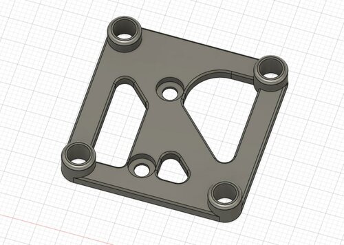
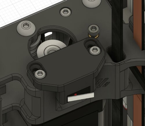
Toolhead PCB To CAN Mounting Adaptor
Simple mount to convert Afterburner Toolhead Board mount spacing to the spacing for popular CAN toolhead boards like Huvud and FLY-SHT42.
The assumption is that you have created an evenly spaced pair of holes to mount to with spacing for the afterburner toolhead PCB (version 4.0 and below). For example, on my 2.4 with a Galileo Stealthburner I am using hartk's Galileo Body. If you need spacers, they should be easy enough to create in Tinkercad or just by overlaying cylinders in your slicer.
BOM
4x M3 Heat Sets (Standard Voron Spec) 2x M3x6 BHCS to mount through to PCB holes 4x M3x6 SHCS for board mounting (or whatever is suitable for your board)47 downloads
-
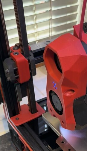
Mount For Electreeks Camera
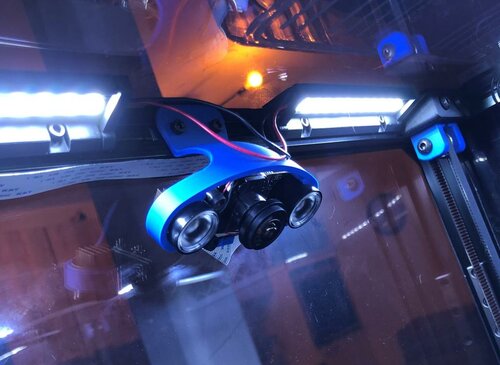
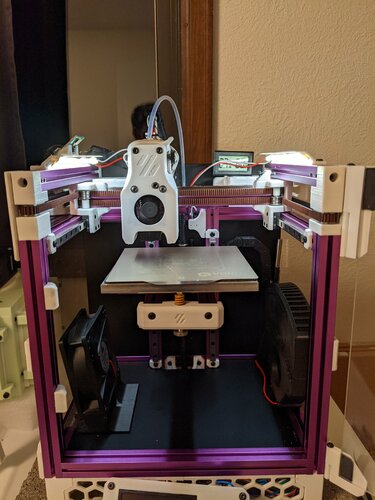
This is a simple mount for the currently popular Electreeks Camera (and the similar models of other brands). It is supposed to be mounted on one of the top Aluminium Profiles of the Voron 2.4 (see picture) maybe it also fits on other printers with closed frame and 20x20 profiles. You need two M3x8 Screws and two M3 slot stones to mount it.
40 downloads
(0 reviews)0 comments
Submitted
-
RockNRoll
RockNRoll - Rockers for Voron V2.4
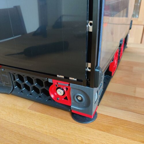
This mod is intended to make access to the electronics compartment easier by enabling the printer to be rolled on its back without damaging cables or the exhaust system. The rockers are mounted on the vertical extrusions in the back replacing the panel corners. Additionally they are braced against the horizontal back extrusion. The mod is designed for and tested with a 350mm V2.4, but it might work with a V1 or Trident as well. Due to their higher center of gravity V1 and Trident might need additional feet higher up. If you tried this mod on a V1 or trident, let me know how it went on discord.
Gallery:
To give you an example how this works, take a look at these pictures:
Hardware needed:
pcs. name 4 M5x10 BHCS 4 M3x12 SHCS 2 M3x20 SHCS 4 M5 T-nut 4 M3 T-nut 2 M3 Threaded Insert As all these are in the BOM of a V2.4 it is highly likely you can build this mod with leftovers from your printer.
Printing:
Parts:
To start off you need to print these parts:
1x rocker_right 1x rocker_left 1x rocker_right_brace 1x rocker_left_brace If you use thicker panels or foam tape than the default 4mm, there is a 6mm version in a subfolder.
For additional support you can swap the base plates of the rubber feet to the ones from this mod. If you are building a 2.4r2 print these:
1x base_plate_a_r2 1x base_plate_b_r2 If you still have an 2.4r1 build you therefor need:
1x base_plate_right_r1 1x base_plate_left_r1 Print Settings:
This mod needs rigidity and stiffness. Based on the Voron recommendations for structural printer parts these settings are recommended:
0.4mm Nozzle 5 Perimeters 40% Infill 10 top and bottom Layers The test prints in the pictures are done with Formfutura rTitan ABS.
Support:
All the STLs are oriented correctly. The rockers themselves have overhangs where the backpanel is supposed to sit. Don't forget to remove the three support tabs integrated into the 3D model before mounting:
Assembly:
Threaded Inserts:
Start with melting the M3 threaded inserts into the braces:
Mounting the Braces:
Remove the bottom corner panel clips of the back panel and insert the T-nuts. Put two M5 T-nuts into each vertical extrusion and two M3 T-nuts on each side of the horizontal extrusion. Put the braces roughly in place and screw them in lightly with two M3x12 SHCS bolts each.
Mounting the Rockers:
Make sure the T-nuts line up with the holes in the rockers and mount the rockers on their braces. They should slot right in. Bolt rocker and brace together with a M3x20 SHCS bolt before mounting the rocker on the vertical extrusion with two M5x10 BHCS bolts. Once every bolt is in place, tighten them all up.
Optional: Mounting the Base Plates:
To increase the support of the rockers you can swap out two of the original base plates of the rubber feet with the ones of this mod. They slot into the rockers tip and support it while tilting. There are STLs available for both 2.4r1 and 2.4r2. The mounting example shows the r1 version, mounting the r2 version is similar.
Start with playing your favorite Elvis song and rocking and rolling the printer on its back for the first time. Remove the rubber feet and the stock base plates:
Swap the M5 nut of the stock base plate to the new one and slot the fork tips of the new base plate into the rocker. Then screw everything back together:
3,923 downloads
-
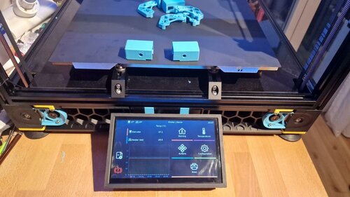
BTT PiTFT
Overview:
This mod adds a mount for the BigTreeTech PiTFT. Currently the mod works for the PiTFT70, but im planning on adding a 5
433 downloads
- Mac10goesBRRRT
- v2.4
- (and 1 more)
(0 reviews)0 comments
Submitted
-
front idler V2.4 Dual Screw Front Idler Mod r3
After a couple of chewed ab belts and finding that the r1 front idlers were the culprit i looked into r2 idlers but didn't like the screw going through the join/split and personally i think that is a bad design feature so i then looked at other idler mods but didn't like the look of those either because to me i didn't think they kept the look of the voron, i have nothing against those designs but wanted to keep the original look of the parts but with better functional integrity so i modified r1 idlers to 2 screws keeping the part join/seam in the middle facilitating the screws going through either side of solid media allowing for an even pull on the idler pulley and even slight alignment adjustments if needed, i have been running this mod now for over 80hrs printing and is working fantastically....
Print as per Voron Spec and only requires 2 extra heat sets and 2 extra m3 screws with washers...
808 downloads
-
voron2.4 Voron V2.4 Klicky Probe Purge Bucket 350mm
This is my solution to the klicky probe far left mount and purge bucket mod. where the probe arm would hit the purge bucket when moved on the Z axis.
if there is any issue please comment and let me know
Credits:
@edwardyeeks: Decontaminator Purge Bucket & Nozzle Scrubber Printing:
Default Voron settings, correct orientation, no supports needed!
269 downloads
(0 reviews)0 comments
Updated
-
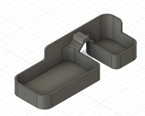
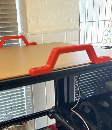
handles 2020 Enclosure Handle
I needed Sturdy Handles for my heavy voron2.4 350 so i could move it and turn it on its side/back to facilitate maintenance but as the enclosure limits where you can hold it and also due to the enclosure creating a step over the aluminium extrusion (3mm plexi and 1mm foam tape) normal handles wouldn't work so i designed this handle to fit the top framing, i can now carry the whole thing to another room if needed....
parts used:
2x M5x15mm BHSC
2x M5 Tnuts
Printed with standard voron specs
105 downloads
-
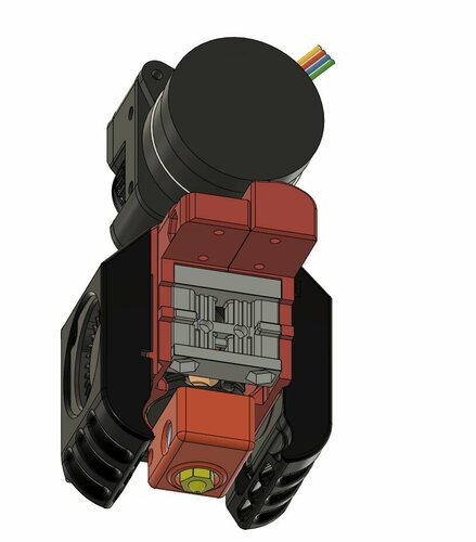
Bondtech LGX lite / Dragon HE ! VORON ZERO
Description
PDF LGX Lite due Dragon hotend on V0 3d printer
Bondtech lgx lite is the best extruder i never tested , it's light weight and compact and uses rounded pancake 36 stepper motor.
which for me the best extruder can be done on the small printer like V0.
5x hex Nut (2 for the fans 2 for Retension_Block , 1 for sandwich main body left /Right ) 2x m3x40 (Fans housing mount (cooling part fans ) ) 3x m3x25 ( 1 for sandwich main body left /Right , 2 for mounting the toolhead on the X- carriage ) 2x m3x12 (mounting the front fan HE fan) 2x 2.5x8mm (for the dragon hotend) 4x m2x8 (for mounting the toolhead on the x-carriage (mgn7) ) 2x m3 heat set inserts (mounting the front fan (HE fan) ) 2x m3x10 (mounting the lgx lite on the main body )
check out my other desigh with HExtrodr mount on voron zero here !
205 downloads
-
V0 Bed Fan
Bed fan mount for the V0. Uses an 80x80x25mm fan, I used this GDSTime one. It makes the enclosure heat up faster, and the bed cool down faster after prints.
Fan definition:
[fan_generic enclosure_fan] pin: PB8 max_power: 1.0 shutdown_speed: 0 cycle_time: 0.01 hardware_pwm: False kick_start_time: 0.1 off_below: 0.2 Klipper macro for preheating the enclosure:
[gcode_macro PREHEAT] gcode: M140 S110 ; Preheat bed M104 S160 ; Preheat hotend M106 S255 ; Part fan at max {% if 'xyz' not in printer.toolhead.homed_axes %} G28 ; Home axes {% endif %} G0 X60 Y60 Z110 F5000 ; Move bed down and AB to middle M190 S110 ; Wait for bed to hit 110 SET_FAN_SPEED FAN=enclosure_fan SPEED=1 If you use this, make sure to also turn off the enclosure fan in the PRINT_START:
SET_FAN_SPEED FAN=enclosure_fan SPEED=0 Klipper macro for cooling down the bed after the print ends:
[gcode_macro COOLDOWN] gcode: {% if printer.toolhead.position.z < 110 %} G0 Z110 F3600 {% endif %} TURN_OFF_HEATERS SET_FAN_SPEED FAN=enclosure_fan SPEED=1 M106 S255 ; Part fan to max [gcode_macro PRINT_END_COOLDOWN] gcode: M400 ; wait for buffer to clear G92 E0 ; zero the extruder G1 E-4.0 F3600 ; retract filament COOLDOWN {% set max_y = printer.configfile.config["stepper_y"]["position_max"]|float %} G0 X60 Y{max_y} F3600 M190 S50 ; Wait for bed to cool down (note: will heat to 50) M190 ; Turn off bed ; Turn off fans SET_FAN_SPEED FAN=enclosure_fan SPEED=0 M10723 downloads
(0 reviews)0 comments
Updated
-
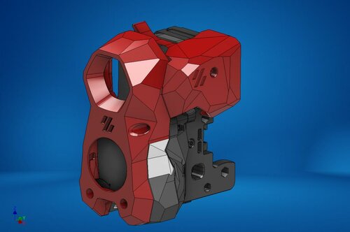
Orbiter 2 Clockwork (beta)
Orbiter 2 Clockwork Module (beta)
This Clockwork module allows the use of the Orbiter v2 Extruder in the Voron Afterburner.
THIS IS A PRE-RELEASE - DO NOT DOWNLOAD UNLESS YOU ARE WILLING TO DEAL WITH POSSIBLE ISSUE OR TO GIVE FEEDBACK!
The rear screws that hold the chain anchor on are m3x8, two of them. They use the Voron heat set inserts, m3 I was working with DoubleT on the PCB holder. Trying to build a universal tool version so we could use different holders.
16,762 downloads
- orbiter2
- spacelab2021
- (and 4 more)
-
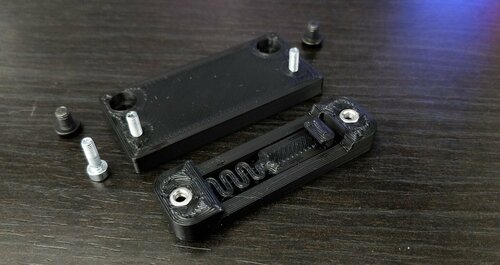
PSU Meanwell LRS-200-24 Stiffer DIN Mount
I wanted to use Demosth's Stiffer DinMount for my PSU, but as I had ran out of self tapping screws and didn't want to wait for new ones to be delivered I modded his design slightly to accept M3 screws and nuts. Because the spacing between the screw holes would not fit the PSU's mounting holes center-to-center distance without interfering with the spring design, I added a very simple base plate which bolts onto the PSU using M4x6 screws.
Assemble the DIN bracket onto the base plate first, then the base plate onto the PSU.
These mounts are for PSUs with mounting holes 50mm apart center-to-center.
The tolerances of the holes are tight, so your printer has to print with dimensional accuracy or the screws won't fit.
If too tight for your printer, try using Hole Horizontal Expansion in your slicer.
Photo sample printed with 0.3mm layer height, 0.5mm width, 7% infill, complete set of 4 in about 37mins.
No supports needed.
Hardware:
M3x10 SHCS x 4 M3 nut x 4 M4x6 BHCS x 4
316 downloads
(0 reviews)0 comments
Updated
-
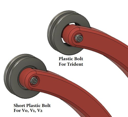
HorseshoeSpoolHolder
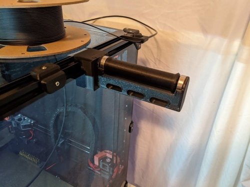
Horseshoe Spool Holder
This is a method to mount the filament spool inside the enclosure of a Voron Trident 3d printer, or outside a V0, V1 or V2 printer. It works with 200mm, 1kg spools only.
For mounting internally in the Trident, the ptfe tube is installed as shown: up through the gap in the side of the rear extrusion. Alternately you could drill a 4mm hole though the B stepper mount top and bottom parts.
To install the spool: Feed the filament through the ptfe first, then align the spool into the front and top bearing rings, and pull forward to spring the frame and drop into the rear bearing ring.
BOM:
3 608 bearings (any type) 2 M5-8mm (pan/socket) head bolts and 2 M5-Tnuts for 2020 extrusion only OR 4 M3-8mm (pan/socket) head bolts and 4 M3-Tnuts for 1515 extrusion 3 - M3-8mm bolts (pan/socket)
Internal Version for Trident only
Print PlasticBolt(x3) and use a m3-8mm PH or SH bolt to secure the pin in place.
External version for V0, V1, V2
Print ShortPlasticBolt(3x) and use a m3-8mm PH or SH bolt to secure the pin in place.
Please provide feedback for issues/suggestions to #Logan2225 on VoronDesign Discord. Thanks!
1,035 downloads
- LoganFraser
- v0
- (and 3 more)
-
Rear Umbilical
Rear Umbilical Addon and Y Endstop Relocation
BOM Pieces M3 Heatinsert 4x M3x10 SCHS 4x
since my a/b motor mounts are MJF single pieces i needed a way to add umbilical compatibility without the need to reprint anything. so i designed this. its however heavily based on Selliot79's Design. i just designed it to be a bit smaller, to fit a IGUS CF5.05.18 perfectly and moved the mountings to the rear, so theres space for a Y Endstop relocation
979 downloads
-
Stealthburner CW1 PCB Cover
Stealthburner Clockwork1 PCB Cover
I designed a cover for users who are still rocking the CW1 with Stealthburner, with the same low-poly esthetic of stealthburner. This cover is a snug fit, so please make sure your wiring is all nice and tidy or you could have some issues.
388 downloads
-
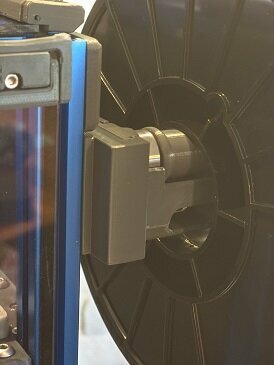
Roller Holder Mount-Voron Vertical
I needed a better spool holder solution after the stock Voron one got worn and caused drag, which in turn was causing extruder skipping. The bearing supported one looked like a winner, but none of the mounts available put it in the stock location where I wanted it.
I took the mount part and the stock Voron part and merged them into this part. Now the holder mounts in the stock location and does not interfere with the side or top panels.
Remixed just the frame mount to go with ahough's remix of the original.
298 downloads
- v2.4
- claudermilk
- (and 1 more)
(0 reviews)0 comments
Updated
-
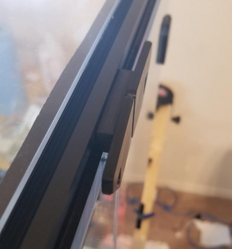
Door Hinges
Voron 2.4 Hinge Mod for 3mm Doors with 3mm Foam
This is designed for 3mm door panels with 3mm of foam. I used the laser cut panels from Printed Solid which are 3.175 (1/8") and the foam tape from Amazon. They are design to fit Misumi extrusions. If the width of your extrusion is not the same, you can adjust the part that goes into the extrusion.
Make sure the panels you use are cut to specifications. 0.5mm too large on each panel can cause issues. Also, make sure you flow rate is dialed in. There isn't much room in the design for over-extrusion.
The M3x40mm bolt used as a pin is designed to fit tight in the hinge. It will pivot when the door is opened/closed so don't tighten it too far in the insert below. You will need to thread the bolt in the top part of the hinge and when your bolt hits the non-threaded part (assuming your bolts are not 100% threaded) you will need to persuade it thru the hinge pivot block. Once thru, I would back it out and go back in a couple times.
If you are over extruding, you will have difficulty getting the bolt into the hinge. Feel free to use the step file to open the hole up if you need to. I did not want any play in the hinge.
I recommend drilling the holes in the panel with a 4mm or 5/32" bit made for acrylic. If you do not have an acrylic bit available, please find some guides and/or watch some videos on how to successfully drill your panel. If you have scrap acrylic, please try it first. Having a hole a little larger than the bolt will provide some "wiggle" room. You can loosen the bolt, move the panel a little and tighten back up. The edge of the panel might catch on the bolt that goes into the extrusion, so some filing may be needed. (See Photo 1/2)
The backplate on the hinge helps spread the load and prevents cracking of the panels. You do not need to use them if you have shorter bolts and don't want to use them. I would, however, recommend using them. The handles do not have backplates. As long as you do not over-tighten them, they should be fine. Use some button heads if you can. I didn't have any, and found socket heads work just as well.
There is not much space behind the inserts on the hinge. Be careful and do not press them too deep. Press them "almost" in and then use something like a straight edge to press them flush. It is easy to dimple the front side, especially if you use too long of bolts. (See Image 4 below).
Final note: The pivot has a little "ear" that overhangs the other side of the extrusion. This is ensure the pivot is solid and fits square against the extrusion. It does mean that that you will not have foam on that part. (See Photo 2)
Handles
item qty M3x6 BHCS x8 M3 inserts x8 Hinges
item qty M3x40 x4 (hinge "pin") M3x12 SHCS x4 attaches pivot to frame M3x10 BHCS x8 attaches hinge to door panel M3 inserts x12 Image 1:
Image 2:
Image 3:
Image 4:
Photo 1:
Photo 2:
Photo 3:
Photo 4:
Photo 5:
Photo 6:
Photo 7:
3,908 downloads
-
External_sdcard_socket_mod
In my travels upgrading Anycubic mega-S printers, I created a sdcard socket mount for the cabinet to plug into a MKS Robin Nano control board. I remixed my design to add the same functionality in my Voron 2.4r2 300mm build. I can create other skirt mods if there is interest.
printed parts
right skirt with sdcard socket modification sdcard mount sdcard cover Other parts required
6 M3x8mm screws for mounting sdcard extension cable You do need a micro sdcard to sdcard extension cable. I picked up mine on Amazon made by Lanmu. It is a 500mm long extension cable and works well with the hardware positioning that I did for my machine. They do make a 250mm also which may work better for some installations. All you need to do is remove the plastic end cover for installation in the mount I designed.
68 downloads
(0 reviews)0 comments
Updated
-
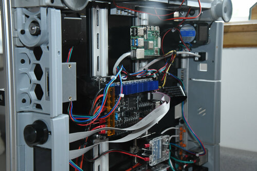
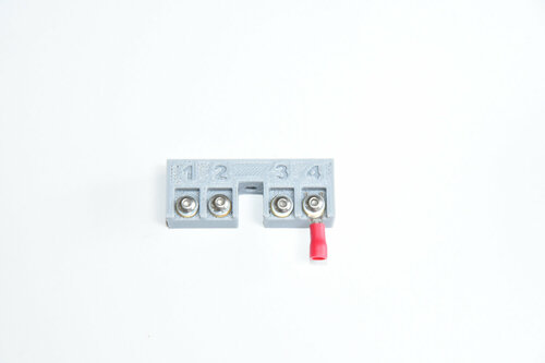
rail_tie_block
My designs I have done for high power rocketry bays led me to design connector blocks specialized for that environment. I have taken one of my older designs and remixed it to mount as a right angle four post block for signal and fan wiring. I do like the WAGOs but only for AC/Mains. This block gives you four isolated posts in a space that fits into a extrusion rail with a M3 hammerhead nut.
Printed Part
4_post_Wiring_Block_M3_rail Other parts
four M3 thermal inserts one M3x12 screw for mounting block one M3 hammerhead T-nut four M3x6 pan head or button head non-oxide screws (shiny) four M3 internal lock washers eight M3 brass washers You can use spade terminals or wrap a loop of wire between the brass washers. Personally, I would use a spade terminal for the controller connection and just strip off the ends of the fan wires, twist them together and wrap it around the post. When a fan goes bad, replacement would be the easist this way.
Of note, I have the panels from Printed Solid shown in the picture. The block is only 12mm high, so it can fit against the panel for use in the electronic section.
17 downloads
- eletronics
- mods
- (and 3 more)
(0 reviews)0 comments
Submitted
-
Vertical PSU Mount
Vertical PSU Mount
For vertically mounting the meanwell or equivalent PSU across two din rails. Adjustable so you can account for rail distance.
92 downloads
(0 reviews)0 comments
Updated
-
PurgeBucket 350 Klicky
Purge bucket (Klicky) Mod.
Credits:
@edwardyeeks: Decontaminator Purge Bucket & Nozzle Scrubber Basically his design is already perfect, there is nothing really to improve on it. I just made a small Cut-Out for the Klicky (which you can do tbh yourself with a side cutter xD) Printing:
Default voron settings, correct orientation, no supports needed! Bom:
see: Decontaminator Purge Bucket & Nozzle Scrubber Description:
The bucket itself is v2.4 350 only compatible. I don't know and can't test the dimensions of a 300/250... But it's a dumb cutout anyway only. Description (Only for Blurolls-Kit Owners)
The Blurolls kit includes M4 Knurling-Nuts, that are a bit smaller and shorter as BOM (DIN466) ones. The difference is: BOM-> height: 9,5mm / OD=16mm Blurolls->height: 8mm / OD=12-14mm So for exactly this reason, this repo includes a modified Brush-Holder.611 downloads
-
Decontaminator Purge Bucket
A Team Dropbear Production
(Note this mod is no longer maintained but is kept for historical purposes.)
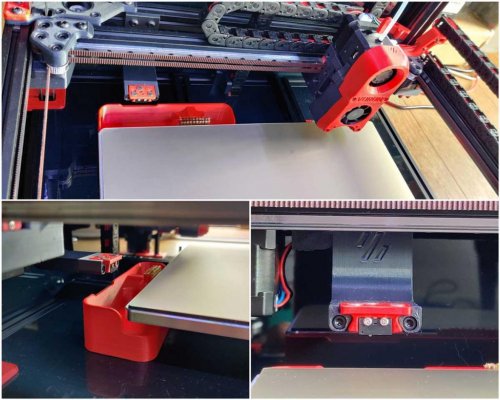
Decontaminator Purge Bucket & Nozzle Scrubber
This is a removable purge bucket with a nozzle scrubber. It is compatible with Voron 1.8 and Voron 2 printers (v2.4, v2.2 and v2.1). I noticed that the current nozzle scrubber design of the Voron was not very effective at containing filament debris and bits.
It was also not removeable, making it a pain to reach behind and clean it out with a vacuum. So, this design aims to solve all that by:
Making a larger and deeper purge bucket to hold more filament gunk. Purge bucket is removeable and naturally clips onto the brush scrubber with its geometry. Magnets help secure it further with the added benefit of a satisfying 'clip' sound when attached. A spring steel sheet stop/index is provided for convenience when putting your spring steel sheet back on the plate. These use M2x10 self tapping screws that allow you adjust the height so that they're flush with the print surface. Installation & Parts Required
Pictures shown are slightly older versions, however, installation is exactly the same.
The geometry of the brush_holder is such that it clips and holds the brush in place through friction fit. As noted in the installation guide, do not try to force the brush in if it's the wrong size; it will break quite easily.
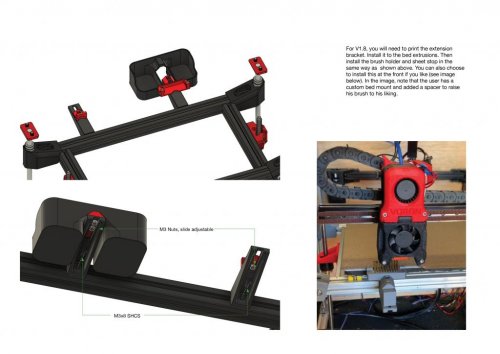
For V1.8, you will need to print extension_bracket_v1.8 (print 2x if you want to use the individual sheetstop). Some may opt to install it at the front.
You will need the following:
1x brass brush or whatever you prefer (I got the TriangleLabs brass/copper brush and cut it down to length). For V2.1, 2.2 & 2.4: 2x M3x8mm SHCS (3x if you use the sheet stop option) For V1.8: 3x M3x8mm SHCS (5x if you use the sheet stop option). 2~3x M2x10(or 8, or longer)mm self tapping BHCS/SHCS (optional if you wish to use the sheet stop function). You should have these from the V1 and V2 BOM which are spec'ed for the microswitches. 2~3x M3 nuts (for V1.8 only) 2x 6x3mm round magnets STLs are included here and CAD files as well if you wish to change the dimensions or modify to your liking. A purge and nozzle scrub macro that is plug and play is provided as well; you can find them under Macros. Shoutout to community member Hernsl for providing this macro!
NOTE: If you are using the z endstop from V2.2, there is a version of the stop that takes into account the locating bolt heads of the endstop. You can simply mirror the stop in your slicer if your endstop is on the other side of the extrusion.
HISTORY OF REVISIONS
The purge bucket & nozzle scrubber has undergone many revisions within a short time, especially between Rev3 and Rev4. To avoid confusion and provide clarifications to current users of the purge bucket and prospective users, please read the following:
Rev1+2 and Rev3 are intercompatible with each other. They only work on V2.2 and V2.4. Rev4 is a completely standalone revision (only individual sheetstop remains unchanged, rest are not backwards compatible with Rev1+2 and Rev3 and vice versa). This revision works on V1.8, V2.1, V2.2 and V2.4 and the same parts are shared across all platforms. You will be able to find these older revisions under Legacy_Revisions.
REV1+2 AND REV3
In Rev1+2, the brush holder was available as two options: a regular holder and one with fully printed sheet indexing stops. In Rev3, the brush holder became only available as a printed sheet stop option with M2X10 BCHS self tapping screws. Purge buckets were compatible across Rev1+2 and Rev3.
REV4 (LATEST)
V1.8 support was added in this revision. Due to screw distances changing in V1.8 to allow clearance from the rear electronics panel, I made the decision to have this change apply to the V2 versions so that one part can be used across V1 and V2. This would minimise hunting for specific parts for each specific printer. However, this means that only the individual_sheetstop carries over from previous revisions (purge bucket dimensions have changed as well).
Future revisions may include the use of a silicone brush that is gentler on plated nozzles. Come back for updates!
-edwardyeeks (edwardyeeks#6042)
15,910 downloads
-
270 Clamping Hinges
270 Degree Clamping Hinges
The design of this hinge is based on chrisgonzales already incredible 270 degree hinges. The main goal of this remix was to have the front panels mounted in a way that didn't use any VHB tape or holes that needed to be drilled into the acrylic, and of course, use minimal amounts of additional hardware. After many design iterations and improvements I came to a solution.
Important Notice
If you're going for a super sealed enclosure, then these hinges are not for you. In testing ( at the moment with only 2 hinges per panel ) I found after opening and closing the doors several times, they would slowly lose alignment ( only by fractions of a mm ) and just need a little push to re-align so the panels would close properly and not collide. This means you'll probably have a gap of a couple mm between the panels at the front if you don't want to be driven crazy by them not staying super aligned. A potential fix would be to print 3 hinges for each panel but I am yet to test this although I strongly recommend you do use 3 hinges per panel if you have a printer larger than 250x250 ( what I'm testing them on ).
Update Log
11.12.21 - Made subtle changes to dimensions to hold panels closer together whilst having them fully seated in the clamps for maximum strength, also changed recommended print settings for stronger face_plate_bottom.stl.
Using Foam Tape
At the moment I have only tested using 3mm thick foam and that works well, you may be able to get away with 4mm foam, but for anything thicker, you'll need to modify part of the hinge to accommodate this.
Keeping The Doors Shut
I am currently using clamps designed by v6cl
Different Styles Of Face Plates
The file names match up with the digrams below.
Face Plate No Logo Face Plate Embossed Logo Face Plate Through Logo BOM - Per Hinge
Printed Parts
face_plate_top.stl [x1] face_plate_bottom.stl [x1] side_mount.stl [x1] Additional Hardware
M3 x 8mm SHCS [x5] M3 Hex Nuts [x2] M3 T-Nut [x1] Printing
I recommend following the default settings for Voron Parts, and none of the parts require support material.
Layer Height : 0.2 mm Extrusion Width : 0.4 mm Infill : 40 % ( 100% For face_plate_bottom.stl ) Perimeters : 4 Solid Top/Bottom : 5 Supports : No Brim : Optional Assembly
Better photos will come in good time 😉
Attach the _face_platebottom to the _face_platetop using 2x M3 x 8 mm Bolts and 2x Hex Nuts - Keep the bolts loose for now Attach the faceplate assembly to the _sidemount using 2x M3 x 8 mm Bolts - Again, don't overtighten these so the hinge moves easily Install the finished hinge assembly to the frame using 1x M3 T-Nut and 1x M3x8mm Bolt - Position them now to your liking Once all the hinges are on the frame. Slot in a panel on one side, before tightening down the M3x8mm Bolts in the faceplate assembly. And repeat for the other panel. Loosen the panel's clamps and position accordingly, repeat for the other panel. For the handles, I just re-used the correct ones that chrisgonzales made :).
Installed On My 2.4
Better photos will come in good time 😉
3,139 downloads
-
2.4 Spool Holder
I really like this spool holder and had to make a Voron 2.4 adapter for it. I didn't want it to interfere with the glass panels, so it's been designed to avoid touching them at all.
BOM:
Roller Holder Mount x1 Roller Holder x1 Roller x1 Skateboard Bearing x2 (can be substituted with plastic bearings provided as stl files) 3x12mm SHCS x1 3mm T-nut This has been a welcome addition to my printer.
Print Settings: Supports: Yes Resolution: 0.2mm Infill: 40-50% Wall Thickness: 1.6mm Here is a link to the original version of this spool holder:
https://www.thingiverse.com/thing:3020026
Update: 5/4/2022
Depending on where you mount the spool holder and how you are routing your filament, you may need an extended bowden tube guide. After some questions around this, I have included the STL file for the an extended version of the stock Voron 2.4 bowden tube guide incase you run into this issue.
3,274 downloads
.thumb.png.b4c8b560bac8a00c8b37819de85ea291.png)