Search the Community
Showing results for tags 'hartk1213'.
-
Version 2021.06.26
282 downloads
MGN9C X axis This replaces the MGN7H rail on the V0.1 X axis with a single MGN9C rail. Required hardware In addition to things you can reuse from the stock build, these items are required: 1x MGN9C-150mm linear rail 7x M3x8 7x M3 Nuts Instructions Assembly is exactly the same as the stock V0.1 X axis Images -
Version 2023.01.20
133 downloads
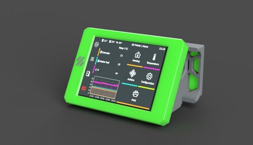
Voron 0.2 Waveshare 2.8 DSI Display BOM Waveshare Display DSI Cable This display mount attaches using stock hardware on the V0.2 as well as the hardware that is included with the display Thanks DragonKitty! for testing the display mount To install the display follow the driver installation procedure on waveshares website here if you find that the drivers that you need are not included in the waveshare repo, they removed older versions but i have zipped and uploaded those here along with the old instructions from waveshare After the drivers are installed run the following command to open up the config.txt for the raspberry pi cd ~ sudo nano /boot/config.txt This line you added in the driver installation dtoverlay=WS_xinchDSI_Touch,invertedy,swappedxy,I2C_bus=10 Needs to be changed to dtoverlay=WS_xinchDSI_Touch,invertedy,invertedx,I2C_bus=10 save and exit that file then while still ssh into the pi you will need to place this file in the following directory, you may have to create that directory if it is not already created /usr/share/X11/xorg.conf.d/ now you can proceed with installing klipperscreen as normal i typically use kiauh to do that as it makes it that much easier -
Version 2021.12.15
211 downloads
SexBolt Z endstop This an alternative way to do the Z endstop pin in a V2, instead of using a deflanged GT2 20T pulley, it uses 2 5x7x8 sleeve copper bearings/bushing this is pretty simple to assemble. The reason behind this is to help keep the pin from falling out. BOM Screws Size Qty Link M4x8 SHCS 1 Bolt Depot - M4x8 SHCS 5mmx20mm Binding Screw 1 Amazon - Binding Screw M2x8 Self Tapping 4 Amazon - M2x8 SHCS Self Tapping 5x7x8 Sleeve Bearing 2 Amazon - Sleeve Bearing Z endstop PCB 1 Formosissima - Z endstop PCB Full kit can be purchased here First just insert two of the sleeve bearings into the top, they should bottom out with about 2mm or so poking out the top Next insert the female side of a 5mmx20mm chicago screw (sex bolt, binding barrel) and screw in the M4x6 or M4x8 SHCS with some loctite to make sure it doesn't move over time Next insert the Z endstop PCB and secure it with 4 m2x10 self tapping screws Next just secure it to your V2 like you would the stock Z endstop This mod was based on the work done by Voron Discord User L.e.o.p.a.r.d for the Micron 3d printer. -
-
-
Version 2020.12.09
138 downloads
Hinged Hat for the V0 This is my new design for a fold away hinged top hat for the V0, i have included the step file for all the parts i designed, as well as added a BOM for everything you need to get in order to build this, assembling is pretty straight forward i have added the steps i took when assembling it in picture form here Step 1 NOTE: This step uses M3x12 screws Is to attach the bottom hinge pieces to the top of the V0 first with the little pegs on the bottom of the bottom hinges going into the holes on the A and B drive parts on top of the V0 using M3x12 screws Step 2 NOTE: This step uses M3x16 screws attach the 200mm extrsusion to the printed parts Step 3 NOTE: This step uses M3x8 screws next is the rear frame for the top hinge assembly, attach the two top hinge pieces to a 200mm extrusion as shown, be aware that these pieces are mirrors of eachother and it matters which side they go on, they are attached using m3x8 screws Step 4 NOTE: This step uses M3x8 screws next is to add these 200mm extrusions to the top hinge assembly created in previous step, these also use m3x8 screws Step 5 NOTE: This step uses M3x8 screws attach the 2 80mm extrusions up against the top hinge assembly Step 6 NOTE: This step uses M3x8 screws attach the 170mm extrusions that go up against the 80mm extrusions Step 7 NOTE: This step uses M3x8 screws now add the 92mm extrusions to the front of the frame, now these are 92mm long but the gap between the top and bottom extrusion is 95mm, you want the top of the extrusion to be flush and leave a little gap in the bottom of them which is for the alignment pins Step 8 NOTE: This step uses M3x8 screws these are the alignment pins, they are used to register in the holes on top of the front idlers on the V0 and they just attach to the bottom of the 92mm extrusions Step 9 NOTE: This step uses M3x8 screws attach the 2 front extrusion and you should have the completed frame now Step 10 NOTE: This step uses M3x20 screws what I would do next is attach the bottom hinge and top hinge together using the middle hinge assembly you made in step 2 and check to make sure every thing is moving correctly and lining up properly, and make any adjustments you see fit. final step Once the frame is moving correctly and everything is working well together, add the panels to the top hat to enclose it completely there are 2 panels that go in the back the inner one can be left out, I originally didn't have the final rear printed panel but now that it's there , the inner rear panel is no longer needed Screw size and locations bottom hinge uses m3x12 to attach to the frame using an m3 nut that needs to be slid into the top extrusion of the V0, I did this by unscrewing the front of it from the idler bracket and just dropping a nut in the extrusion top hinge which also uses an m3x12 and m3 nut in 1 of the 3 holes to attach it to the bottom of the top extrusion of the hat frame the other 2 are m3x8 and are screwed into the ends of the extrusions the middle hinge (middle screw) is an m3x16 and it screws into the end of the middle extrusion the middle hinge (2 outer screws are m3x20) they screw into embedded nuts on the back of the middle hinge piece i hope the pictures help with assembly they are named in the correct order to assemble it when it comes to drilling the holes in the extrusions to screw them together, there is a drilling guide stl in the stl folder and it has 3 holes, the one closest to the end is for the 92mm extrusions on the bottom of them, the same end that the alignment pin stl gets screws on. the middle hole in the driling guide is just a standard 7.5mm from the edge to make normal blind joints you did with the v0 and the highest hole is to attach the 80mm extrusion to the top 200mm extrusion (you drill the hole in 200mm extrusion) i found it easier to assemble it from the back of the top hat forward. if you open the step file you can see how it assembles. i have tested this quite a bit and so far its been working great! please feel free to make any modifications to it as you see fit i hope you enjoy it -hartk1213 V0.108 BOM 1515 Extrusions Length (mm) Qty Misumi Part Number 200 5 HFS3-1515-200 170 2 HFS3-1515-170 92 2 HFS3-1515-92 80 2 HFS3-1515-80 Enclosure Panels Location Dimensions Qty Front 212x76 1 Sides 182x76 2 Top 212x212 1 Rear 212x59 1 Screws Size Qty M3x8 68 M3x12 4 M3x16 2 M3x20 4 M3 Nuts 64 Pictures -
Version 2022.04.23
2,357 downloads
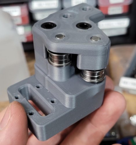
This has been updated for V2.4r2 and Trident This mod is for the V2/Trident, it involves printing new AB drive frames, new XY Joints, new Front Tensioners, and new Z idlers The pins have replaced m5 screws, at any location where the screw acts like a shaft, holding bearings, pulleys or idlers. This allows for smoother rotation and stops the possibility of motion parts being caught in threads. This work was done by everyone, thanks to ABS plastic and voron printers for the fast iteration, @doomweasel? they fall out yet? To complete this mod the following files will need to be reprinted A and B drive units a_drive_frame_lower_pinned.stl a_drive_frame_upper_pinned.stl b_drive_frame_lower_pinned.stl b_drive_frame_upper_pinned.stl Front Idlers [a]_a_tensioner_pinned.stl [a]_b_tensioner_pinned.stl XY Joints MGN12_xy_joint_left_upper_pinned.stl MGN12_xy_joint_left_lower_pinned.stl MGN12_xy_joint_right_upper_pinned.stl MGN12_xy_joint_right_lower_pinned.stl Z Idlers FOR V2 either one of these based on if you are using 6mm or 9mm belt [a]_z_tensioner_x4_6mm_pinned.stl [a]_z_tensioner_x4_9mm_pinned.stl here is what the XY Joint will look like here is what the Z idler will look like the following 5mm Pin hardware is what is needed as well BOM [A-B] 30mm (x2) 28mm (x2) [X-Y Joints] 40mm (x4) [X-Y Idlers] 43mm (x2) [Z Idlers] 28mm (x4) these can be purchased from here Smooth pins https://www.aliexpress.com/item/1739093502.html Misumi Part Numbers Part NO. Qty SFR5-30 2 SFR5-43 2 SFR5-40 4 SFR5-28 6 The following users are the main contributors to this mod @RoboDave @DeepFriedHeroin @Hartk @DOOMweasel @Eddie -
Version 2021.12.07
598 downloads
SexBolt Z endstop This an alternative way to do the Z endstop pin in a V2, instead of using a deflanged GT2 20T pulley, it uses 2 5x7x8 sleeve copper bearings/bushing this is pretty simple to assemble. The reason behind this is to help keep the pin from falling out. ASSEMBLY MANUAL BOM Screws Size Qty Link M4x8 SHCS 1 Bolt Depot - M4x8 SHCS 5mmx20mm Binding Screw 1 Amazon - Binding Screw M2x8 Self Tapping 4 Amazon - M2x8 SHCS Self Tapping 5x7x8 Sleeve Bearing 2 Amazon - Sleeve Bearing Z endstop PCB 1 Formosissima - Z endstop PCB Full kit can be purchased here or here (Aliexpress affililate link for HartK) First just insert two of the sleeve bearings into the top, they should bottom out with about 2mm or so poking out the top Next insert the female side of a 5mmx20mm chicago screw (sex bolt, binding barrel) and screw in the M4x6 or M4x8 SHCS with some loctite to make sure it doenst move over time Next insert the Z endstop PCB and secure it with 4 m2x10 self tapping screws Next just secure it to your V2 like you would the stock Z endstop This mod was based on the work done by Voron Discord User L.e.o.p.a.r.d for the Micron 3d printer. -
Version 2021.04.26
256 downloads
This mod moves the Y endstop to the A drive, to go along with Arkeet's MGN12 mod that has the X endstop on the toolhead. This mod requires a 2 pin JST-XH to be soldered to the switch. The best way I have done it is to solder the wires to the JST-XH first, install it with a dab of super glue, then solder the wires to the Omron switch. There are 2 different files non pinned version a_drive_frame_upper_with_jst_y_endstop.stl pinned version (since this mod also works with the Voron2.4_Pins_Mod): a_drive_frame_upper_with_jst_y_endstop_pinned.stl here are a few pics for reference you might need to bend the pins a little bit to get them to fit around the curve -
-
- 1
-

-
- afterburner
- clockwork
-
(and 3 more)
Tagged with:
-
-
- 1
-

-
- afterburner
- galileo
-
(and 1 more)
Tagged with:
-
Version 2021.04.26
5,091 downloads
This mod is for the V2, it involves printing new AB drive frames, new XY Joints, new Front Tensioners, and new Z idlers The pins have replaced m5 screws, at any location where the screw acts like a shaft, holding bearings, pulleys or idlers. This allows for smoother rotation and stops the possibility of motion parts being caught in threads. This work was done by everyone, thanks to ABS plastic and voron printers for the fast iteration, @doomweasel? they fall out yet? To complete this mod the following files will need to be reprinted A and B drive units a_drive_frame_lower_pinned.stl a_drive_frame_upper_pinned.stl b_drive_frame_lower_pinned.stl b_drive_frame_upper_pinned.stl Front Idlers [a]_a_tensioner_pinned.stl [a]_b_tensioner_pinned.stl XY Joints NOTE: There are now 2 versions of these files , 1 set for Stock 2.4 and 1 set for Arkeets MGN12 xy_joint_left_upper_pinned.stl xy_joint_left_lower_pinned.stl xy_joint_right_upper_pinned.stl xy_joint_right_lower_pinned.stl or MGN12_xy_joint_left_upper_pinned.stl MGN12_xy_joint_left_lower_pinned.stl MGN12_xy_joint_right_upper_pinned.stl MGN12_xy_joint_right_lower_pinned.stl Z Idlers either one of these based on if you are using 6mm or 9mm belt [a]_z_tensioner_x4_6mm_pinned.stl [a]_z_tensioner_x4_9mm_pinned.stl here is what the XY Joint will look like There is a new file for the A Drive to go along with Arkeets MGN12 mod that has the X endstop on the toolhead the files for the endstop relocation mod are here Voron2.4_Y_Endstop_Relocation the following 5mm Pin hardware is what is needed as well BOM [A-B] threaded @ 30mm (x2) smooth @ 28mm (x2) [X-Y Joints] smooth @ 40mm (x4) [X-Y Idlers] smooth @ 43mm (x2) [Z Idlers] smooth @ 28mm (x4) these can be purchased from here Smooth pins https://www.aliexpress.com/item/1739093502.html threaded pins https://www.ebay.com/itm/φ5mm-φ12mm-Female-Thread-Cylindrical-Pin-Dowel-Pins-A2-304-Stainless-Steel/184373551069 Misumi Part Numbers Part NO. Qty SFRT5-30-M3 2 SFR5-43 2 SFR5-40 4 SFR5-28 6 NOTE: 2 smooth pins can be substituted for the threaded pins, the reason the threaded pins are there is for easy removal without the need to remove the stepper. but if you dont plan on removing the pins without removing the stepper than smooth pins would work just fine for you in this situation. The following users are the main contributors to this mod @RoboDave @DeepFriedHeroin @Hartk @DOOMweasel @Eddie -
-
Version 2020.09.10
54 downloads
Deck Panel for V0 to include the Voron logo and the VORON0 name i used user @Kruppes blank deck panel to make my own to include the logo as well as the words it uses 3 colors hence the 2nd accent label on the 3rd stl [b], i used black for the base, red for the logo and gray for the -
-
Version 2020.09.10
5 downloads
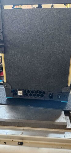
C14 Fused inlet for the V0 with a cover on the back to cover the contacts This is a mount for a c14 fused inlet found here on amazon https://smile.amazon.com/Antrader-Module-Socket-Switch-IEC320/dp/B07CTC5JVV this uses 2 M3x40 screws to assemble and 2 M3x12 screws to attach to the frame Pictures

