-
TeamFDM.com is an UNOFFICIAL companion site for the DIY Voron 3D printer community. For official docs and final source of truth, visit the Official Voron Discord or the Voron Github
Printable Voron User Mods
Voron User Mods, or "UserMods", are a collection of community created and Team FDM curated modification for Voron Printers. All of these mods are available on the VoronUsers Github repo and unless otherwise specified follow the Voron communities GPL3.0 Licensing. Use any Mods at your own risk, if you make modification please share them on the VoronUsers repo.
Mod Authors: Have a Voron mod? Upload it at TeamFDM.com and let us know you're the author. We will ensure you can update and curate your files for more feedback! Please include tags for what Voron, or extruder your mod is compatible with.
660 files
-

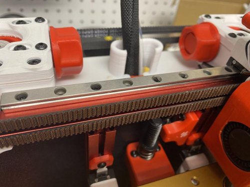
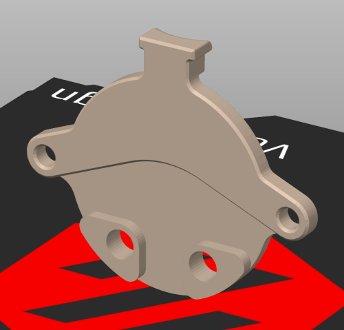
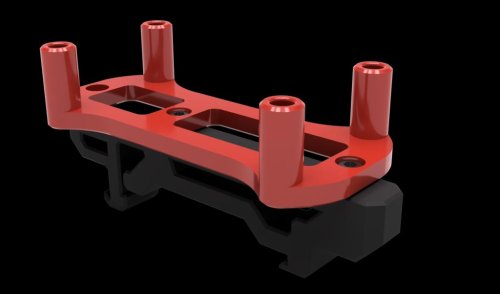
V01 Motor Panel No Rub
Voron v0.1
What is this?
This modification keeps the umbilical and reverse bowden tube from rubbing against the motor belts.
How do I use it?
Replaces the Motor Panel and reuse the same M3x8 screws
How should I print this?
Same as any other Voron part. Printed with Polylite ASA
56 downloads
(1 review)0 comments
Updated
-
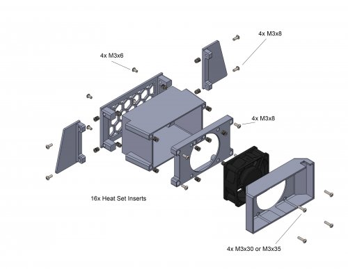
Tophat Exhaust Filter
After growing tired of my room smelling of ABS, I decided to create an exhaust and filter system that could be printed entirely on a v0. This mod utilizes 5 layers of 10mm thick activated charcoal sheets, a 60mm x 25mm fan and an optional Roomba HEPA filter. I have tested it throughly and my design almost entirely eliminates the ABS smell during and after printing.
The entire assembly (With the HEPA filter attachment) sticks out about 110 mm past the rear of the printer.
BOM
4x M3x6 screws 8x M3x6 or M3x10 screws 4x M3x30 or M3x35 screws 16x Heat set inserts 10mm Activated Charcoal sheets Link 24v 60mm x 25mm fan Link OPTIONAL Roomba HEPA filter Link Assembly
Before printing the Fan_Cover make sure to check where the wires from your fan exit the housing and select the corresponding stl. The fan wires snake through the assembly and exit through one of the holes in the grill. You will also need to cut 5 55mm x 90mm sheets of activated charcoal to fit into the chamber
Wiring and Klipper
If you're using an SKR mini v1.2 then you must move the hotend fan from pin FAN0 to FAN1. This allows the exhaust fan to be controlled via PWM instead of the hotend fan since the 1.2 board only has 1 controllable fan port. If you're using the v2 then you don't have to worry about that step because both fan ports are controllable.
Add this to your config assuming the exhaust fan is plugged into FAN0 (PA8)
[fan_generic exhaust_fan] # Exhaust Fan pin: PA8 max_power: 1.0 shutdown_speed: 0 kick_start_time: 0.5 You can then control the fan speed with
SET_FAN_SPEED fan=exhaust_fan SPEED="number between 0 and 1" For example, to put the fan speed at 30% use,
SET_FAN_SPEED fan=exhaust_fan SPEED=0.3 Running the fan at 30% speed during a print has lead to a dramatic decrease in ABS fumes and pretty much made them unnoticeable. I also run the fan at 100% speed at the end of a print to fully exhaust the print chamber. Adding foam tape to seal up any gaps between panels and the top-hat will also greatly increase the reduction of fumes.
243 downloads
(0 reviews)0 comments
Updated
-
350mm Side Skirt_for Generic Power Plug v2.4 r1
Right rear side b for a Voron 2.4 r1 350 with generic power plug.
44 downloads
(0 reviews)0 comments
Updated
-
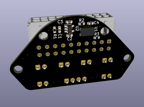
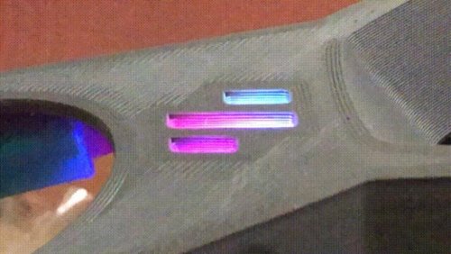
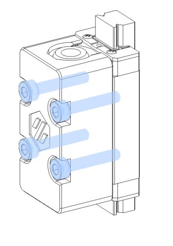
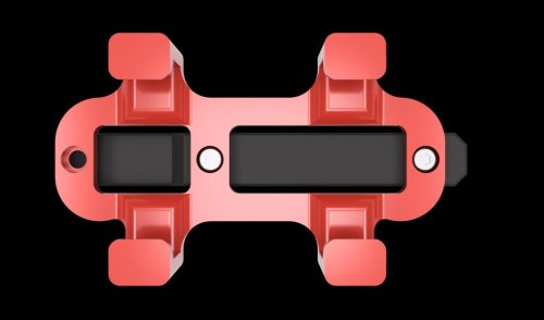
Voron-0 Umbilical PLUS (with integrated ADXL345)
The Voron-0 Umbilical is a well known and very useful addition to your 3D Printer, originally created by GitHub user timmit99 and can be found in the official Voron-Hardware repository here.
In this new 'Plus' version, I have added a permanent ADXL345 Accelerometer to the Toolhead board, to make input shaper tuning (and possibly other interesting use-cases) more accessible to users. The Molex MicroFit connector was changed from a 14-pin to 20-pin version to acommodate the additional wires for the ADXL345.
The Toolhead PCB can be ordered pre-assembled from JLCPCB (using the included CPL and BOM file) so you do not have to solder the delicate electronics yourself, just the connectors (as you need to do with the original V0-Umbilical).
You can find a full README and Photos/CAD/Design data at my github repository: https://github.com/skuep/V0-Umbilical-Plus
Frame PCB BOM
Part Quantity Notes LCSC Part Number Link 20 Pin Socket 1 MOLEX 430452012 C485575 https://www.lcsc.com/product-detail/Wire-To-Board-Wire-To-Wire-Connector_MOLEX-430452012_C485575.html SMD Thermistor 1 100K 0805 Thermistor C143680 https://lcsc.com/product-detail/NTC-Thermistors_Vishay-Intertech-NTCS0805E3104FXT_C143680.html 2 pin JST XH 5 2.5mm pitch C158012 https://lcsc.com/product-detail/Wire-To-Board-Wire-To-Wire-Connector_JST-Sales-America-B2B-XH-A-LF-SN_C158012.html 3 pin JST XH 2 2.5mm pitch C144394 https://lcsc.com/product-detail/Wire-To-Board-Wire-To-Wire-Connector_JST-Sales-America-B3B-XH-A-LF-SN_C144394.html 4 pin JST XH 3 2.5mm pitch C144395 https://lcsc.com/product-detail/Wire-To-Board-Wire-To-Wire-Connector_JST-Sales-America-B4B-XH-A-LF-SN_C144395.html 6 pin JST XH 1 2.5mm pitch C144397 https://www.lcsc.com/product-detail/Wire-To-Board-Wire-To-Wire-Connector_JST-Sales-America_B6B-XH-A-LF-SN_JST-Sales-America-B6B-XH-A-LF-SN_C144397.html Screw Terminal 1 5.08mm pitch C8465 https://lcsc.com/product-detail/Screw-terminal_Ningbo-Kangnex-Elec-WJ500V-5-08-2P_C8465.html Optional Parts
Part Quantity Notes LCSC Part Number Link 0805 10uF Capacitor 3 Use if using BARE neopixel IC's. Strips have these already. C17024 https://lcsc.com/product-detail/Multilayer-Ceramic-Capacitors-MLCC-SMD-SMT_Samsung-Electro-Mechanics-CL21A106KPFNNNE_C17024.html Toolhead PCB BOM
Part Quantity Notes LCSC Part Number Link 20 Pin Socket (Right Angle) 1 Molex 430452000 C485576 https://www.lcsc.com/product-detail/Wire-To-Board-Wire-To-Wire-Connector_MOLEX-430452000_C485576.html 2 pin JST XH 6 B2B-XH C158012 https://lcsc.com/product-detail/Wire-To-Board-Wire-To-Wire-Connector_JST-Sales-America-B2B-XH-A-LF-SN_C158012.html 4 pin JST XH 1 B4B-XH C144395 https://lcsc.com/product-detail/Wire-To-Board-Wire-To-Wire-Connector_JST-Sales-America-B4B-XH-A-LF-SN_C144395.html LP2985-33DBVR 1 3.3V LDO C95414 https://www.lcsc.com/product-detail/Linear-Voltage-Regulators-LDO_Texas-Instruments-LP2985-33DBVR_C95414.html ADXL345BCCZ 1 Accelerometer C9667 https://www.lcsc.com/product-detail/Motion-Sensors-Accelerometers_Analog-Devices-ADXL345BCCZ-RL7_C9667.html 10 Ohm Resistor 2 0603 size C22859 https://www.lcsc.com/product-detail/Chip-Resistor-Surface-Mount_UNI-ROYAL-Uniroyal-Elec-0603WAF100JT5E_C22859.html 10 kOhm Resistor 1 0603 size C25804 https://www.lcsc.com/product-detail/Chip-Resistor-Surface-Mount_UNI-ROYAL-Uniroyal-Elec-0603WAF1002T5E_C25804.html 4.7uF Capacitor 2 0603 size C19666 https://www.lcsc.com/product-detail/Multilayer-Ceramic-Capacitors-MLCC-SMD-SMT_Samsung-Electro-Mechanics-CL10A475KO8NNNC_C19666.html 10nF Capacitor 2 0603 size C57112 https://lcsc.com/product-detail/Multilayer-Ceramic-Capacitors-MLCC-SMD-SMT_10nF-103-10-50V_C57112.html/?href=jlc-SMT Corresponding CPL and BOM files are included in the repository. Using these files you can easily get yourself a ready-made assembled PCB from JLCPCB so you don't have to have the skills to solder the fine-pitch and 0603 packages.
Umbilical cable
The Umbilical cable is a 220-240mm dual ended 20P (2x10) microfit cable. The connectors are wired 1:1 so pin 1 connects to pin 1 and so forth for all 20 pins.
Cable BOM
Part Quantity Notes LCSC Part Number Link 20 Pin Plug 2 Molex 430252000 C485324 https://lcsc.com/product-detail/Connectors-Housings_MOLEX-430252000_C485324.html Crimps 20 AWG 12 Molex 430300001/430300007 C259786 https://lcsc.com/product-detail/Line-Pressing-Terminals_MOLEX-430300001_C259786.html Crimps 26 AWG 28 Molex 430300004/430300010 C259765 https://lcsc.com/product-detail/Line-Pressing-Terminals_MOLEX-430300004_C259765.html 20AWG Wire 12 220mm Sections PTFE/Silicone/Hefulon for motion rated, PVC could work since it isn't constraind to a cable chain 26AWG Wire 28 MicroFit connectors support two different ranges of conductor thickness using different wire crimp ferrules. I recommend that you realize the stepper motor and heater wires with 20AWG wire (0.5mm²) and the remaining wires in 26AWG wire (0.14mm²) to save on weight and accelerated mass.
Hints and Remarks
Extruder Stepper Direction
The umbilical cable reverses the stepper rotation direction. I.e. you need to invert the DIR pin of the extruder motor in your printer.cfg file.
[extruder] .... dir_pin: PB4 # Add ! (or remove ! if already there) before 'PB4' ....
Mounting the Toolhead PCB
The umbilical toolhead PCB uses heat stake inserts in order to mount it to the motor screws. In some cases (i.e. LDO motors), the extruder motor already has an additional thread, which has to be either removed by drilling the motor holes with a 3mm spiral drill. If you do not want to drill into the motor, you can use M3x10 captive screws, which are unfortunately hard to find. These screws have a narrowed section and a short thread at the tip so they only 'grab' the thread of the heat stake inserts.
Additional chamber thermistor on SKR mini V2.0
If you are using the SKR mini V2.0 board and you want to connect the chamber thermistor, you can use Timmit99's expansion board (https://github.com/VoronDesign/Voron-Hardware/tree/master/SKR-Mini_TFT_Thermistor_Board).
If you want an easier and faster solution, you can move the Z-STOP endswitch pin and connect it the E0-STOP pin using a simple self-made JST 2-pin to 3-pin adapter (See Photos folder) or by removing the crimp pins from the 2-pin JST and insert them into the housing of a 3-pin JST header. Once the Z-STOP pin is freed up, you can use it for your thermistor. This method needs the following printer.cfg changes:
[stepper_z] ... endstop_pin: ^PC15 # Conversion for additional thermistor (use E0-STOP for Z-STOP) ... [temperature_sensor chamber] sensor_type: Generic 3950 sensor_pin: PC2 gcode_id: C pullup_resistor: 10000
Connecting the ADXL345 to a Raspberry Pi
The ADXL345 circuit on the toolhead PCB includes a R-C filter and a 3.3V low-dropout regulator to deliver a clean power supply. Thus you can use the official drawings shown in the corresponding docs (https://www.klipper3d.org/Measuring_Resonances.html), with one small change. You need to connect VCC to +5V (Pin 2 or Pin 4) instead of 3.3V (Pin 1) on the Raspberry Pi extension header (See Photos folder). Then follow the official docs for setting the resonance measurement up.
191 downloads
(0 reviews)0 comments
Updated
-
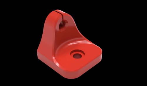
V0.1 - Mini Afterburner ADXL345 Mount
This is a modified version of the strain relief for the mini AB, which provides a well-hidden permanent mount for a cheap Chinese ADXL345 module.
You need 2x 4mm heat inserts as well as 2x M3 6mm screws to attach it.
67 downloads
(0 reviews)0 comments
Submitted
-
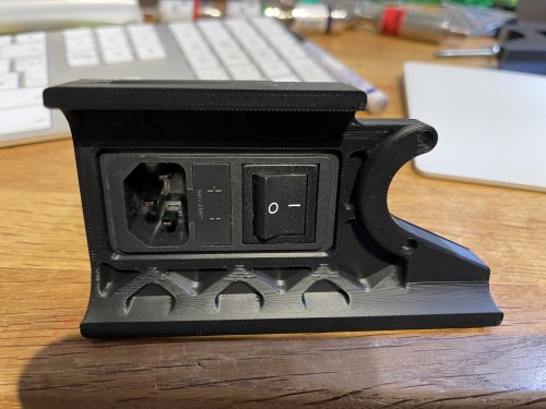
Schaffner FN-286-10-06 plug panel for 2.4r2
I love the Schaffner power inlet - highest quality, and much more safe than other cheap Chinese ones.
So I made a quick mod for my next 2.4r2 build.
Hope you like it
14 downloads
-
CRTouch Snap Mount
Voron 2.4 CR Touch Snap Mount (Beta)
Drop-in Probe Replacement for v2.4 Using Single or Double MGN9 Rail(s).
Stealthburner Compatible but Will NOT Fit on MGN12 (Trident or V2.4r2)!
I've been looking for simpler alternatives to the common probe mods that is also compatible with the standard MGN9 mount. This requires no modification to the printer and uses existing mounting holes and routing. It does require part of the probe's shell be trimmed and must only be powered by 5V!
The big question is, are these even reliable on a Voron? Well, it is well known that BL Touch probes have issues with heat in closed chambers but the CR Touch photoelectric sensor and metal pin design seem to be better suited for this. I'm currently testing reliability but so far have had no significant issues inside an enclosure with temperatures ranging from ~45-60C. Creality lists a max operating temp of 65C but I haven't found much more information. I'm now testing on my v2.4 and will update with any issues.
I'd appreciate feedback from anyone who has used a CR Touch on their Voron or would like to help test. I suggest newer builders stay with the standard options or the well-tested clicky mod.
Finalized CAD files will be posted after beta.
BOM
Size Qty Creality CR Touch 1 M3x8 or M3x10 BHCS/SHCS 2 M3x5 Heat-Set Insert 2
Rear Spacer is Optional
Instructions
With the wiring detached, carefully seperate the 2 shell pieces by gently pressing the 2 clips on each side. Only the probe side will be used. Be very careful not to break the clips off.
Cut off the top mounting tabs so nothing extends past the sides of the shell. I used a dremel finished off by a file in about 5 min. Careful not to damage the components and blow off any debris build up, especially near the sensor.
Press two M3 heat-set inserts into the printed mount then snap the shells together. Make sure all snaps are secured. Tolerances are intentionally tight. If multiple tabs are broken, a strip of electrical tape can be used.
Slide in the probe then attach it from the back with two M3x8 screws (M3x10 recommended with alignment spacer). Longer screws could be used but be careful not to hit the PCB.
Examples shown are on a single MGN9 rail mod
Please contact [email protected] to report issues or suggestions.
115 downloads
-
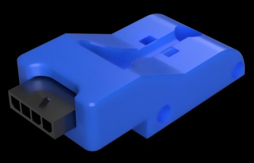
Ab Plug Microfit 1x4
Voron 2.4 AB Plug (Microfit 1x4)
This mod is to add a plug to the gantry to connect the A
138 downloads
-
Esp8266 Nodemcu Din Mount
ESP8266 NodeMCU Din Mount
Designed to hold an ESP8266 NodeMCU. ESPs are commonly used to control LEDs using the WLED project. The ESP can be mounted in either direction.
The model included can be mounted to the original 2.4 din clip or the newer Trident din clip.
Printing
Default voron settings No supports needed BOM
Size Qty M3x8 4 M2x10 2 Trident PCB Din Clip 1
20 downloads
(0 reviews)0 comments
Submitted
-
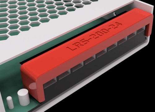
Lrs Screw Terminal Cover
LRS Screw Terminal Cover
Designed to cover the screw terminals for several LRS style PSUs. Other Meanwell PSU may work. Feel free to ping me in discord to add to the compatibility list below.
Pro tip: These are very snug to the point it will bow. This is intentional as it was designed to take some effort to take off.
Printing
Default voron settings No supports needed Compatibility List
LRS-50 LRS-200
495 downloads
(2 reviews)0 comments
Submitted
-
Kirigami LED Bed Front
V0 Kirigami bed front with space for LED
This is a modifaction of the V0 Kirigami front bed made by Kosh42EFG
BOM
Kirigami bed: https://github.com/christophmuellerorg/voron_0_kirigami_bed 1x Kirigami_LED_Bed_Front.stl printed in ABS using standard Voron settings 1x Kirigami_LED_Bed_Front_defuser.stl printed in any white material 2x M3x8 CHCS 2x M3 nuts 1x LED. I use a single neopixel mini button 4x wires for the neopixel (you can use three if this is the only one in the chain) Installation
Install the kirigami bed Wire the neopixel and place in the slot with the wires coming out through the tunnel Add the defuser in front of the neopixel, make sure it is a tight fit to hold it well (print thicker if needed) Fit the Kirigami_LED_Bed_Front.stl to the front of the kirigami bed using the M3 screws and nuts Add configuration change to the printer.cfg in klipper: [neopixel my_leds] pin: PA8 chain_count: 1 color_order: GRB initial_RED: 1.0 initial_GREEN: 0.0 initial_BLUE: 0.0100 downloads
(0 reviews)0 comments
Submitted
-
V0 Belts Holder
Belts Holder
The purpose of this mod it's to ease the printer belt's maintenance.
Usage
Here I needed to replace my x-carriage part. It broke and I glued it for a few days as an emergency.
First, you attach the belts holder to the x-axis inserting it just behind the belts. Then you fix with belt holder's bars the belts, don't tighten too much.
I could remove the x-carriage without having to lose the idlers or have to fight with belts to replace it.
140 downloads
-
Vsw More Robust Belt Paths
More robust Voron Switchwire belt routing
This mod was created because the original stock parts didn't work well for me. The major part are the moded stepper cages. The stepper cages got tilted usually during tensioning and leading to the axle of the stepper not being parallel with the horizontal plane, which lead to yawning of the belt and increased wear and tear of the belt. Additionaly, the cages parts a and b had the tendency to open up in the bottom, especially when the tensioning screw is one or two mm too long.
The modded version has a through-screw in the bottom and additional screw slot on the top to attach it to the vertical extrusion, to help with proper leveling of the stepper axle. You'd probably be able to address these issues without if you were careful and knew about them. Using this design is just much faster.
Additional mods
The xz blocks have a slot for M5 button head screw that can be used to fix tilting of the blocks w.r.t. the plane defined by the X gantry extrusion. The original blocks have already some measures to prevent this, but apparently those were not sufficient in my case (I was worried about tightening the screws too much, as the plastic already started to give and yet there was still a bit of tilting play).
The upper xz blocks/supports were modded just to help more carefuly define in what position and orientation the blocks should stay. These have the least effect, IMO.
With these, I had printed almost 400 hours without any belt-related issues and the belts look still fresh, no signs of fraying. There exist also similar unofficial mods on Voron discord addressing similar issues but I think this is the most exhaustive version.
Print Instructions
Print Settings: Standard Voron PIF sttings -- at least 40 percent infill, 4 perims, 5 solid layers top and bottom
Quantities: Quantities are noted in the filenames -- each part needs to be printed only in single copy.
Installation
Install should be fairly straightforward, the naming of the parts should follow the original naming, so you could follow the SW manual. Few pictures Please note that the last picture contains an old revision of the upper XZ block (that was reducing the Z travel), but the provided version installs the same way and does not reduce the Z travel. Generally speaking, I suggest tightening the screw attaching the stepper to the vertical extrusion as a very last step.
Overal BOM
6x M5x10 BHCS 6x M5 T-Nut for 3030 2x M3x16 SHCS 2x M3 Threaded Insert (standard700 downloads
-
Vsw More Robust Belt Paths
More robust Voron Switchwire belt routing
This mod was created because the original stock parts didn't work well for me. The major part are the moded stepper cages. The stepper cages got tilted usually during tensioning and leading to the axle of the stepper not being parallel with the horizontal plane, which lead to yawning of the belt and increased wear and tear of the belt. Additionaly, the cages parts a and b had the tendency to open up in the bottom, especially when the tensioning screw is one or two mm too long.
The modded version has a through-screw in the bottom and additional screw slot on the top to attach it to the vertical extrusion, to help with proper leveling of the stepper axle. You'd probably be able to address these issues without if you were careful and knew about them. Using this design is just much faster.
Additional mods
The xz blocks have a slot for M5 button head screw that can be used to fix tilting of the blocks w.r.t. the plane defined by the X gantry extrusion. The original blocks have already some measures to prevent this, but apparently those were not sufficient in my case (I was worried about tightening the screws too much, as the plastic already started to give and yet there was still a bit of tilting play).
The upper xz blocks/supports were modded just to help more carefuly define in what position and orientation the blocks should stay. These have the least effect, IMO.
With these, I had printed almost 400 hours without any belt-related issues and the belts look still fresh, no signs of fraying. There exist also similar unofficial mods on Voron discord addressing similar issues but I think this is the most exhaustive version.
Print Instructions
Print Settings: Standard Voron PIF sttings -- at least 40 percent infill, 4 perims, 5 solid layers top and bottom
Quantities: Quantities are noted in the filenames -- each part needs to be printed only in single copy.
Installation
Install should be fairly straightforward, the naming of the parts should follow the original naming, so you could follow the SW manual. Few pictures Please note that the last picture contains an old revision of the upper XZ block (that was reducing the Z travel), but the provided version installs the same way and does not reduce the Z travel. Generally speaking, I suggest tightening the screw attaching the stepper to the vertical extrusion as a very last step.
Overal BOM
6x M5x10 BHCS 6x M5 T-Nut for 3030 2x M3x16 SHCS 2x M3 Threaded Insert (standard197 downloads
(0 reviews)0 comments
Submitted
-
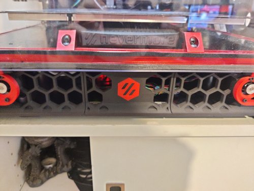
RGB LED Grid For SB
RGB LED grid for the Stealthburner (a.k.a. Rainbow Barf Logo LED)
This PCB, created in KiCad 6.0, is a collaboration between me and tanaes (a.k.a. whoppingpochard). It's a RBG 8× LED grid to be used on the logo of the Voron Stealthburner, to give the user more animation options than a single, boring RGB LED. 😁
Important note: this PCB uses 2.0mm × 2.0mm WS2812B RGB LEDs, they should not be used with RGBW LEDs in the same chain unless you know what are you doing, as they use different data protocols. The usage is possible, but it isn't straightforward. There is information that a workaround for mixing RGB and RGBW LEDs is being developed at the Klipper-led_effect repository, which is what whoppingpochard and I recommend for controlling this board.
Updates
January 16th, 2022: Initial release.
February 18th, 2022: added link for whoppingpochard's Rainbow Barf's repository, and info about Klipper-led-effect developing a solution for mixing RGB and RGBW LEDs. There are little cosmetic differences between that version and the one I've uploaded here, nothing that will change the way it works. Choose whatever suits you better. 🙂
March 17th, 2022: added the KiCad version that was used to design the PCB.
66 downloads
- VinnyCordeiro
- v1.8
- (and 3 more)
(0 reviews)0 comments
Submitted
-
Voron 0.1 - Pi Cam Mount
A webcam mount for Voron 0.1.
Not the best position for a cam but while printing it does its job and it isn't attached to the tophat. It also requires no long cable.
You need the following parts:
- 4x M3 8mm screws
- 4x M2 6mm screws
- 2x Zipties OR 2x M3 15mm screws.
266 downloads
(0 reviews)0 comments
Updated
-
Voron Design Logo STl File
Just thought maybe others might like .stl file as option, Seems to scale nicely.
233 downloads
(0 reviews)0 comments
Submitted
-
(0 reviews)
0 comments
Submitted
-
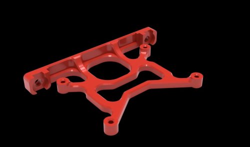
Voron2.4 GE5C
Voron 2.4 GE5C Z joint
BOM
Screws Size Qty M3x12 4 M3x16 or M3x20 SHCS 16 M5x20 4 Ge5C Bearing 4 M5x1mm spacer 4 If using Halleffect 6x3 magnet 1
First just insert GE5C bearing , it should just pop in
Now if you are using the
1,048 downloads
-
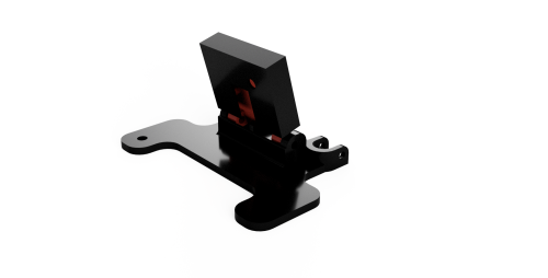
4channel Relay Under Deck Mount
4 Channel Relay Under Deck Mount
Mod to mount a 4 channel GPIO controlled relay in the electronics compartment.
Printing
Default voron settings No supports needed BOM
Size Qty 4 Channel relay 1 M3x8 or M3x6 4 M5x8 2 M5 T-Nut 2
20 downloads
(0 reviews)0 comments
Submitted
-
FIT0729 Camera Housing 2020 rail mount
Housing for a FIT0729 plug&play camera. Top mount Voron 2.4
Printed with Petg Extrudr black matte
96 downloads
(0 reviews)0 comments
Updated
-
Double DIN LRS200-24 Mounts for Voron 2.4
I'm in the middle of my build and mounting my MeanWell LRS 24V and didn't like the options I found which predominantly seemed to be horizontal with the DIN rail. I wanted something turned 90 and clipped to both DIN rails so I modified the ones from the 2.4 Fusion file to work. I'm still quite new to Fusion so somethings not working for you on it let me know but I've already printed and mounted on my power supply where they snuggly hold it in place.
544 downloads
-
Retainer Hardware for 6mm Glass Enclosure Panels
These are sized for a sheet of 6mm Glass WITH a layer of VHB; the base is 7mm tall and the retainer tab is 4mm thick.
48 downloads
(0 reviews)0 comments
Submitted
-
Voyager Gtx Din Mount
Corsair Flash Voyager GTX Din Mount
Din carrier for a Corsair Flash Voyager GTX. To be able to plug in the USB drive you can purchase a small USB extension cable located in the BOM below.
The model included can be mounted to the original 2.4 din clip or the newer Trident din clip.
Printing
Default voron settings No supports needed BOM
Size Qty M2x10 2 Trident PCB Din Clip 1 Corsair Flash Voyager GTX 1 .5ft USB extension (Optional) 1
0 downloads
(0 reviews)0 comments
Submitted
-
Extrusion Thermistor Mount
Extrusion/Chamber Thermistor Mount
Designed to mount a NTC100K Thermistor Sensor to 2020 extrusions.
Printing
Default voron settings No supports needed BOM
Size Qty NTC100K Thermistor 1 M3x8 1 M3 T-Nut 1
377 downloads
(0 reviews)0 comments
Submitted