-
TeamFDM.com is an UNOFFICIAL companion site for the DIY Voron 3D printer community. For official docs and final source of truth, visit the Official Voron Discord or the Voron Github
Printable Voron User Mods
Voron User Mods, or "UserMods", are a collection of community created and Team FDM curated modification for Voron Printers. All of these mods are available on the VoronUsers Github repo and unless otherwise specified follow the Voron communities GPL3.0 Licensing. Use any Mods at your own risk, if you make modification please share them on the VoronUsers repo.
Mod Authors: Have a Voron mod? Upload it at TeamFDM.com and let us know you're the author. We will ensure you can update and curate your files for more feedback! Please include tags for what Voron, or extruder your mod is compatible with.
660 files
-

Microfit 2x3 Skirt Connector Adxl
Microfit 2x3 Skirt Connector (ADXL)
Mod for a Microfit 2x3 connector to be mounted in the bestagons. Typically used for ADXL but can be used as a general connector for anything outside the printer.
Pro tip: I found that adding some hot-glue while installing it into the skirt makes it a bit more robust for unplugging and plugging in.
This is originally based off of this mod. It was modified to not require supports and have a bit tighter fit onto the connector.
Printing
Default voron settings No supports needed BOM
Size Qty Microfit 0430200608 1 Microfit 0430250600 1
265 downloads
(0 reviews)0 comments
Submitted
-
Corner Cable Hide
Top Corner Cable Hide/Cover (LED Wires)
Designed to hide cables that are running around the top corners of 2.4 extrusions behind the z idlers.
They are large enough to fit 3 pin microfit connectors.
There maybe some small loss in z. Don't forget to check your clearances after installing.
Pro tip: It may take some fiddling to get the wires to fit. You will know they are in place when it sits flush to the extrusions without wobbling. Also disable 'Thin Walls/Detect Thin walls' so the mounting ears print cleanly.
Printing
Default voron settings No supports needed BOM
Size Qty M3x8 8 M3 T-Nut 8
562 downloads
(0 reviews)0 comments
Submitted
-
SuperSlim - LED Bar with Simple Bracket
SuperSlim LED
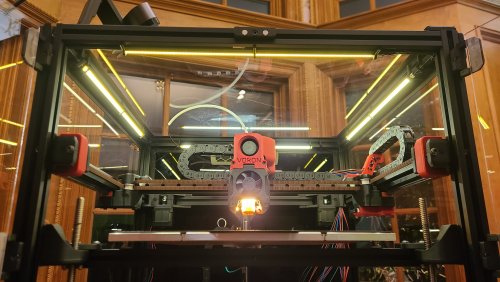
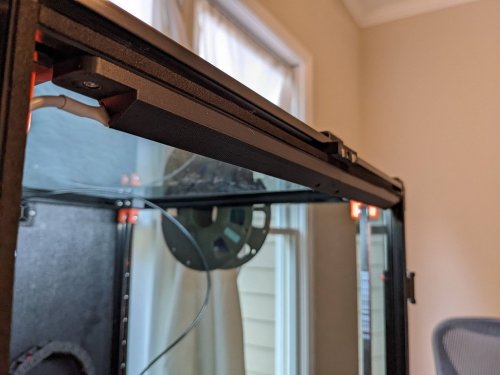
This is a design I'm calling the SuperSlim. It's a super slim LED bar that fits at a 45 degree angle on the 2020 extrusion at the top of your Voron. You print out these small and simple brackets, clip them onto the LED bar and against the extrusion, and presto! You have a gorgeous looking, bright, and simple LED light. Even better these bars use micro LEDs so you get a lot of light diffusion, i.e. no hot spots, and one of the best final looking lights out there for your Voron.
SuperSlim Bracket
The bracket truly makes this design awesome and simple. Here it is in all its simple glory. Print 12 of these. In fact print 20 of these and use them to push/hide your wires tucked into the extrusion slots as well because they're so quick to print, easy to snap in, flexible, strong, sexy looking, and durable. And they're fun to print on your new ABS capable Voron.
Grab the STL or 3MF file attached to this post to print out the bracket using your favorite slicer.
Use 0.3mm layer height for faster prints that are stronger. Use 4 walls to achieve basically no infill. 100mm/s speed should be fine.
Micro LED Bar
Here's a link for the LED light bar on Aliexpress. There are several vendors, so just search 300x6mm LED. Get the Warm White color temperature. Too stark of a bright white is harsh to look at.
300x6mm LED Lights (Pack of 10. About $1.70 each.)
https://www.aliexpress.com/item/32786326547.html
Wiring / Soldering
The light bars are 12V, so to plug them directly into your control board's 24V output, like HE2 (heater 2), so you can control the light from Klipper, you need to wire up 2 of the lights in serial to get 24V. Then wire up the other 2 in serial for another 24V. Then connect those together in parallel to drive off of one heater output.
So connect the + out of HE2 to the + on your first LED bar (LED1). Then connect the - from LED1 to the + on the your 2nd LED bar (LED2). Then connect the - on LED2 to the - on HE2. Go ahead and test out LED1 and LED2 by turning on HE2 using the settings in the section below. Once you're happy, go ahead and finish connecting the last 2 LED bars the same way you did this set of LED bars in step 1 thru 3. Configuring Klipper
You can see it here in Mainsail called "Caselight".
Here is the printer.cfg settings for controlling the LEDs.
[output_pin caselight] # Chamber Lighting - HE3 Connector (Optional) pin: PB11 pwm:true shutdown_value: 0 value:0.06 cycle_time: 0.0002 # with 0.0002 the min is 5%. 7% seems like a good idle state. 40% for prints. over 60% to 100% all seems to be same brightness # with 0.0001 the min is 9%. 12% seems like a good idle state. over 60% to 100% all seems to be same brightness hardware_pwm: True Add some macros as well for convenience.
[gcode_macro LED_ON] gcode: SET_PIN PIN=caselight VALUE=1 [gcode_macro LED_PCT_IDLE] gcode: SET_PIN PIN=caselight VALUE=0.06 [gcode_macro LED_PCT_PRINT] gcode: SET_PIN PIN=caselight VALUE=0.4 [gcode_macro LED_OFF] gcode: SET_PIN PIN=caselight VALUE=0 Then modify your Start / End / Cancel macros so they turn up and down the lights when you start or end your print.
The Start macro...
[gcode_macro PRINT_START] # Use PRINT_START for the slicer starting script - PLEASE CUSTOMISE THE SCRIPT gcode: ;SET_PIN PIN=caselight VALUE=0.4 ; turn on case light LED_PCT_PRINT
The End macro...
[gcode_macro PRINT_END] # Use PRINT_END for the slicer ending script - please customise for your slicer of choice gcode: LED_PCT_IDLE The Cancel macro...
[gcode_macro CANCEL_PRINT] description: Cancel the actual running print rename_existing: CANCEL_PRINT_BASE variable_park: True gcode: LED_PCT_IDLE You should end up with some nice macros that turn your lights on and off at the right time.
This video walkthrough of my serial request will help you get an idea of what these lights look like in a video.
331 downloads
-
LED Light Clip Corner
For use with Eddie's LED_Bar_Clip, this is a 50mm corner piece that hides wire management and fills out the corners. Comes with eyelet for a zip-tie and two M3 loose-fit thru holes for screwing to the extrusion (could modify for clips but would require support to print)
Pieces are 50mm square, on my 250x250 I have 16 of Eddie's clips and one of these on each side. You may need to adjust the size depending on your build, but the FreeCAD file provided should still hold up if you want to adjust the dimensions (I tried reducing to 45mm square and it turned out fine)
Hope this helps with making pretty lights!
~happylittlePCBs
66 downloads
- led
- happylittlepcbs
- (and 3 more)
(0 reviews)0 comments
Submitted
-
Chamber Wire Caps
I was struggling to find a clean way to wire components I was installing to the front and sides of my chamber, so I designed these wire caps to allow me to route the wiring through to the wiring compartment in a much more convenient location without showing the wiring.
BOM:
3x8mm SHCS x1 3mm T-nut x1 3/8" Rubber Grommet Assembly:
Drill a 3/8" hole in the bottom panel (Do not exceed 20mm from the extrusion) Install the rubber grommet Route the wire through the grommet Install the t-nut Tighten the wire cap to the t-nut There are two versions of the wire cap so you can use this print to route wire from either direction. Just make sure to choose the one that works for your use case.
30 downloads
(0 reviews)0 comments
Updated
-
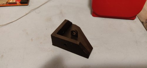
v2.4 45 degree LED mount
This is a two piece LED strip mount. It accommodates 7mm-8mm LED strips and mounts them to 2020 extrusion at a fixed 45 degree angle.
BOM:
Printed Male Mount Printed Male Mount - 1 Printed Female Mount - 1 3mm Socket Head Bolt - 4 3mm T-nut - 4 Strip of 7mm-8mm led lights
Notes:
This was specifically designed to fit my 350x350 build. It would likely need to be scaled down to fit smaller v2.4s I'll add a better wiring photo once I get it cleaned up596 downloads
-
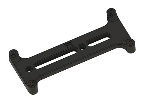
nut adapter for mgn9 rails
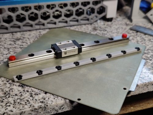
This is a simple nut adapter to keep hex nuts in place inside the 15mm extrusion if you're using mgn9 linear rails. This complements the MGN9 X-axis mod for the V0.1. The hole spacing is 20mm center-to-center between each screw hole and 5mm edge to center on either end.
115 downloads
-
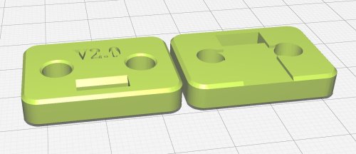
Upper Z Clip Mod V2.0
I'm working on this mod because I only left about an 1 1/2" of belt hanging out of the upper Z clip. I printed it with 100% infill to match other parts printed on a resin printer. I'm hoping others find it useful.
154 downloads
-
Switchwire Front Grill
Why?
I had no intention of enclosing my Switchwire as I have a 2.4. This machine is going to be dedicated to printing PLA so I just wanted a cleaner front middle grill and here we are! Obviously this mod is only intended if you don't plan on enclosing your switchwire.
Installation of the center grill does not change.
7 downloads
(0 reviews)0 comments
Updated
-
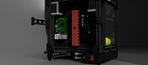
Raspberry Pi Zero Bracket
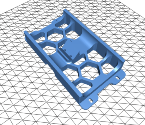
Raspberry Pi Zero Bracket
This is a modified version of the raspberrypi_bracket for the VORON Trident. Use this bracket along with a pcb_din_clip_v2 to mount a Raspberry Pi Zero to a DIN rail.
DIN Rail Install:
The STL file for the pcb_din_clip_v2 is located on GitHub at VoronDesign/Voron-Trident/STLs/ElectronicsBay/
Use six(6):M2x10 Self-Tapping Screws to mount the bracket to the din clip and then the RPi Zero to the bracket. Note that these fasteners are included in the VORON Trident BOM.
VHB Tape Install: This bracket can also be installed on the VORON V0 with VHB tape in the same manner as the stock RPi bracket.
107 downloads
(0 reviews)0 comments
Submitted
-
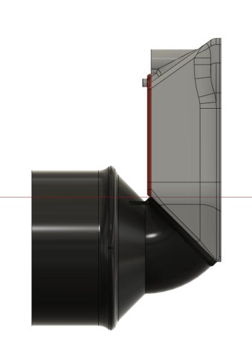
Exhaust Adapter 100mm
Exhaust Adapter to 100mm ventilation system
Please find attached my exhaust adapter to a 100 mm ventilation system. The adapter replaces the original 60mm fan on the exhaust housing of Voron 2.4 and comparable 3d printers.
Printing
Printing succesful with standard VORON settings. Support should not be required, as dedicated structure has been added for increased rigidity and to avoid necessary support structures.
Use the following *.stl file for realization in one print:
VORON2_v2.4_Exhaust_Adapter_100mm_RC3.stl
Additional Material
Bill of Material:
4x M3x8 SHCS bolts 2x 90-110mm hose clamps (e.g. local hardware store) Optional:
1x 100mm Ø flexible ventilation hose (e.g. local hardware store) 4x M3x10 BHCS bolts for reverse mounting 4x M3 hex nut 4x M3 washer Mounting
Replacing the original 60mm fan
Losen the screws of your original 60mm fan and detach the fan from the exhaust housing. Pre-load the mounting holes in the exhaust adapter with M3x8 SHCS bolts and align and fix the adapter to your exhaust housing with the 100mm opening facing away from your printer.
Screwing the bolts at the upper side of the adapter requires a hex key with ball ends. Alternatively you can screw M3x10 bolts inverse from the inner side of the exhaust housing and mount the adapter with M3 washers and hex nuts.
The exisiting 24V supply for exhaust fan can be used with an external SSR for the control of an AC ventilation system or as input for any ventilation valve system in central exhaust system set ups. (Mind electrical isolation between printer and exhaust system !)
Slide a 100mm Ø flexible ventilation hose over the 100mm opening and fix it with one or both of the hose clamps.
Alternatively rigid 100 mm PVC ventilation pipes can be directly slided over the adapter and sealed with remains of 3mm sealing tape from your enclosure panels.
FAQ
No Questions and Answers yet.
Question ?
Answer.50 downloads
- chri.kai.in
- v1.8
- (and 2 more)
(0 reviews)0 comments
Submitted
-
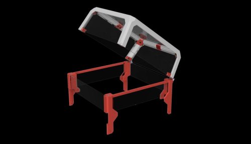
V0 Extended Tophat Hinge
V0.1 Extended tophat hinge
Contents
STL files with print number suffix Manual for simplier assembly - TBD BOM Renders cad file Explanation
For people who cant print hinged tophat parts as it not fits v0 bed, you can print hinge_for_stock_tophat_x2.stl and connect it to default v0.1 tophat with 2x10mm self tapping screws, small 1.2mm holes needs to be made in tophat back parts to secure it with screws.
BOM
In addition to preloaded nuts and screws that are in stock v0.1 you also need:
8 x standard v0.1 BOM magnets 6x3mm optional: 2x10mm self taping screws in case of connecting default tophat with hinge_for_stock_tophat_x2.stl 2 x M3x16 BHCS 2 x M3 Nylon-Insert Locknut Acrylic/PC 3mm thick or printed panels (dxf included) 1 x front plate - 210x48 mm 2 x side plate - 208x45 mm 1 x back plate - 207x48 mm Renders
647 downloads
(0 reviews)0 comments
Submitted
-
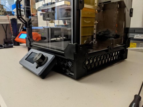
V0 Trident Skirt Mix
V0.1 Trident skirt remix with 12864 LCD
Contents
STL files with print number suffix Manual for simplier assembly BOM Renders Live photos cad file BOM
In addition to preloaded nuts and screw that are in default v0.1 version you need also:
4 x standard v0.1 BOM heat set inserts 6 x M3x12 BHCS 2 x M3x6 BHCS BTT MINI 12864 V1.0 Renders
Live photos
Courtesy of Revnull Courtesy of Revnull
Collaboration
Big thanks for all who gave ideas, showed mistakes and discussed about this little mod.
Especially for:
hartk for lcd_case_front_mini12864 step and stl files DaveR for front_skirt_one_piece.stl and v0.1_trident_skirt_foot_rear_right_bowden_tube_connector_x1.stl594 downloads
(0 reviews)0 comments
Submitted
-
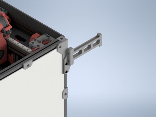
CornerPanel SpoolHolder
Purpose
I originally came up with this mod in order to accommodate my custom hinged rear panel. The stock spoolholder gets in the way of the hinging panel and won't allow it to open without removing the spool holder. This mod moves the spoolholder to the top rear corner panel clip, allowing for easier access to the rear panel as well as providing a more secure mount. It requires minimal hardware and is very easy to install.
Required Hardware
1 x M3 Nut (Square, Hex, or NoDropNut, any will work) 2 x M3x10 BHCS
Print Settings
4 Walls, 5 Top/Bottom, 40% Infill Standard Voron structural part settings. You do want this to be relatively strong.
Install Instructions
Remove stock spool holder. You can reuse the PTFE lengths. Remove left side panel. Remove top rear corner panel clip from the acrylic panel. Hopefully you used VHB instead of glue :) Install the modified CornerPanel onto the side panel. Remove rear left foot and install one extra M3 dropnut (or use NoDropNuts Mod) onto the left side of the rear left extrusion. Reinstall side panel. Install the spool holder using the M3x10 BHCS. One of them will replace the original M3x8 in the old panel clip.
Notes
There are four different CornerPanel files. Each one is sized to different panel thicknesses, like the originals. Pick one that matches your panel thicknesses. There is an additional 3.25mm size just because a lot of 3mm panels tend to be actually 3.15-3.25mm in my experience.
If you find that your spoolholder is slightly skewed to one side or the other, the CAD files are supplied so you can extrude them slightly thicker or thinner to get the spoolholder to stick out perfectly straight. If this part is too thick for your panels, the spoolholder will be skewed slightly to the left (when viewed from the back of the printer). If it's too thin for your panels, it'll be skewed to the right.
When properly sized, the spoolholder will be perfectly straight out the back, and there's little to no chance for the edge of the spool to rub on your back panel.
34 downloads
(0 reviews)0 comments
Submitted
-
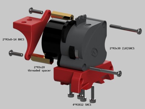
LGX Lite Mount
A mod to mount the LGX Lite to the current X carriage.
Additional Hardware:
LGX lite mount
4* M3x12 SHCS don't forget to install the included nuts with the LGX lite into the extruder housing. 4* heatset inserts Chainmount:
2* M3x30 SHCS low head to match the originals but regular work 2* M3x20 threaded spacer 2* M3x8-14mm BHCS length isn't critical as long as it's between 8 and 14mm 2-3* heatset inserts Installation:
Install heatsets into printed parts. Remove the motor and install the nuts included with the LGX. Attach the LGX to the mount. Reattach the motor using the longer screws. Thread the spacers on the exposed screws behind the motor. Screw the chainmount onto the spacers. Attach to the carriage.
222 downloads
-
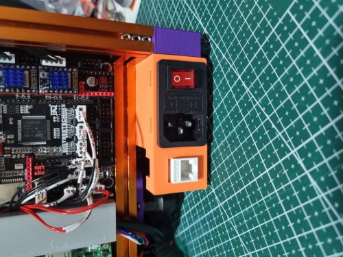
Power Inlet W Keystone Insert
Power-Inlet-w-Keystone-Insert
For Voron 0.1
Description
Adds a keystone slot for the v0.1 Power Inlet. This does not change the way the inlet mounts onto the frame. This was remixed in TinkerCad, using the original v0.1 power inlet, as well as a section of the v2.4 power inlet (the keystone insert portion).
BOM
Keystone insert x1 LAN cable x1 Heatset insert x1 Installation
Install heatset insert (per the original assembly instructions) Cut LAN cable to required length Crimp it onto the keystone insert I used a toolless keystone insert Insert keystone insert into the inlet slot Slide in the prepared power inlet Mount the power inlet per assembly instructions22 downloads
(0 reviews)0 comments
Submitted
-
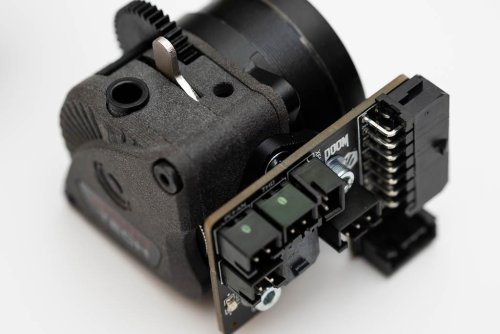
LGX Lite Toolhead PCB Mount
LGX Lite toolhead PCB mount
Use with Mrgl-Mrgl's LGX Lite and cable chain mounts https://github.com/Mrgl-Mrgl/VoronUsers/tree/master/printer_mods/Mrgl-Mrgl/LGX_Lite_Mount
Tested with version 3.2 of the toolhead PCB https://github.com/VoronDesign/Voron-Hardware/tree/master/Afterburner_Toolhead_PCB
Fasteners
2 x M3x5x4 threaded inserts (the standard Voron M3 threaded inserts) 2 x M3x8 countersunk socket head screws to attach the toolhead PCB mount to the LGX Lite body side (with square nuts installed) 2 x M3x8 socket head cap screws to attach the toolhead PCB to the mount (use plastic washers) 2 x M3 plastic washers Notes
install the threaded inserts from the flat side of the mount. This will leave some plastic between the threaded insert and the PCB to prevent damage to traces etc use the spacer or washers between the mount and the LGX Lite body to avoid interference with the gears Images
Fiction#5826 on Discord
332 downloads
(0 reviews)0 comments
Submitted
-
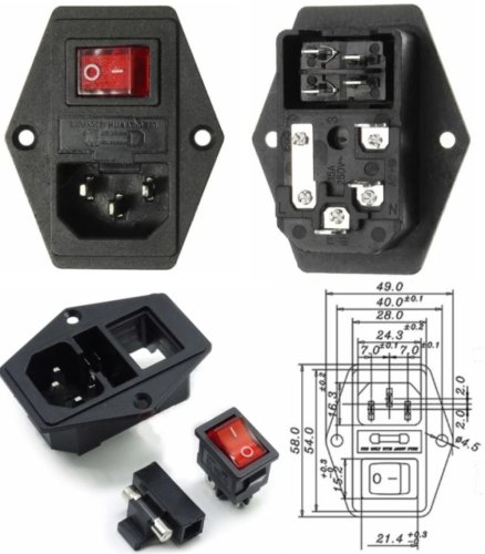
V2.4 Plug Panel Generic Combo
V2.4 Plug Panel Generic Combo
A modified power plug skirt section which accepts generic amazon plug/switch/fuse combo modules with a hexagonal shape (two mounting holes on flanges on the long sides) such as this:
Fasten with 2x M4x10 self-tapping screws.
56 downloads
(0 reviews)0 comments
Submitted
-
Cable Management Duct
Cable Management Duct
Little cable duct for hiding the cable. Can print with your desired color to match with your build. Integrated with zip tie mounts.
For the cable management manual, I refer to: LDO here.
Printed parts
There are two version:
Standard size: if you have a large size printer I refer this. Small size: can print on Voron V0 bed size. Print recommended:
ABS No support needed
2,092 downloads
-
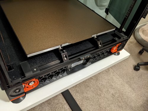
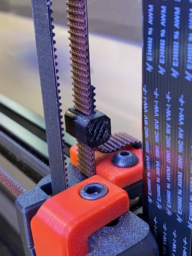
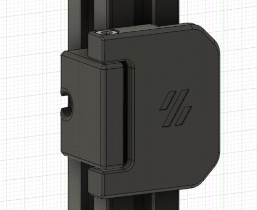
Z Belt Clip
A simple Z belt clip
The 2.4 manual suggested leaving 1 to 2 inch Z belts, however, when the panels are up, the extra belt can drag along the panel. Not sure about adversary effects but not a bad idea to keep it tidy. The clip works for 9mm width belts, also should fit 6 mm. Just print and slide on.
Extra Belts Length Before Panel
Extra Belts Length with Panel
Installed Clip, all cleaned up!
328 downloads
-
Neopixel Holder
Neopixel Mount
These are neopixel mounts that slide into the V0.1's top extrusions (20 leds in total)
BOM
Neopixel/WS2812B led strip (60 leds/m) only 34cm, 20 leds are needed Cables Instructions
Print 4 of the "Neopixel_Mount" (2 for each side) Solder only the 5V and GND wires on the led strips Slide them into the mounts Solder the signal wire based on the diagram below (There is a hole in the mount to allow the wire to go from the one strip to the other) Remove the 2 screws holding each extrusion into place Remove the 3 screws that attach the panels onto each extrusion Slide the mounts onto each extrusion and screw the extrusions in place
93 downloads
-
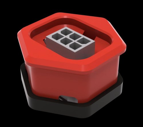
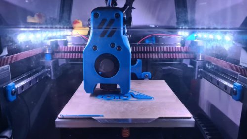
LED Holder
LED Strip Holder
Works on Trident & 2.4 any size.
This mod lets you mount LED strips inside your printer. I mounted three in mine and it is like daylight inside the box.
I used these 24V strips from Amazon and connected them to a fan output on my Octopus board. Works a treat.
You can mount as many "strips" in your printer as you like. I have one on the front rail and one on each side for a total of three. You can cut the strip at the solder obrounds and connect them with wire to go around the corners. I run the wire in the extrusion down to the controller and use an extrusion cover to hold the wires in.
https://github.com/VoronDesign/VoronUsers/raw/master/printer_mods/DerekBackus/LED_Holder/Images/LED_Holder_ISO.png https://github.com/VoronDesign/VoronUsers/raw/master/printer_mods/DerekBackus/LED_Holder/Images/LED_Holder_Side_View.png
https://github.com/VoronDesign/VoronUsers/raw/master/printer_mods/DerekBackus/LED_Holder/Images/LED_Holder_Picture.jpg
85 downloads
(0 reviews)0 comments
Updated
-
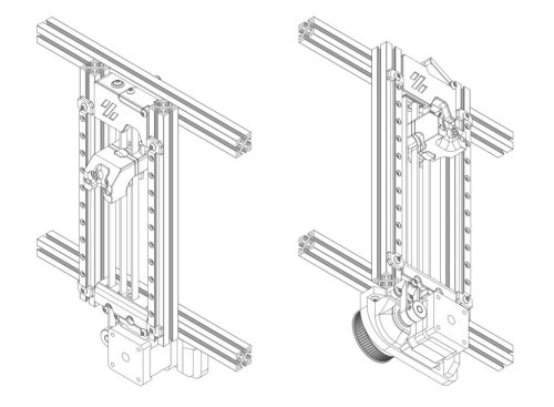
Voron0 Block And Tackle Z Belt
Overview
A block & tackle Z belt implementation for the Voron 0 / Voron 0.1.
The goal was to make use of the original V0 Z motor and timing belt in a compact format, using hardware and screws already in the V0.1 BoM where possible. No additional M3 nuts need to be preloaded - so no disassembly of the frame - though two will need to be inserted into one of the Z axis extrusions.
By default this mod uses 40T & 16T pulleys, combining with the 2:1 of the block and tackle, to give a 5:1 ratio.
Larger pulleys - up to 64 teeth - can be used to increase this ratio, but will require longer timing belts.
The V0 skirt/feet are too short, so this mod requires a taller skirt, such as hartk1213's extrusion skirt mod, doubletrouble023's skirt mod, or my own Trident-style skirt mod (WiP). The V0.1 skirt/feet have enough height, though a 64T pulley may be a squeeze.
Testing has shown there is a maximum of 115mm in Z with the original design. The current files have been modified to address this, but the travel distance has not been tested.
Both the V0 and V0.1 bed positions are now supported - just print the appropriate bed_front_*.stl file.
https://github.com/VoronDesign/VoronUsers/raw/master/printer_mods/MCMBen/Voron0_Block_and_Tackle_Z_Belt/Images/Block_and_Tackle_Z_Belt_Render.png https://github.com/VoronDesign/VoronUsers/raw/master/printer_mods/MCMBen/Voron0_Block_and_Tackle_Z_Belt/Images/Block_and_Tackle_Z_Belt_Drawing.png
BoM
This BoM doesn't include the 2x self-tapping screws, M3x12 BHCS, and Omron switch for the Z stop, though for clarity it does include some hardware which is reused from the V0 and V0.1 builds.
Common
Component Quantity M3x8 BHCS 2 M3x10 BHCS 5 M3x12 BHCS 3 M3x16 BHCS 6 M3x25 BHCS 3 M3x30 BHCS 2 M3 threaded insert 6 3x12 pin 1 F623 bearing 6 F695 2RS bearing 1 MF105 bearing 1 GT2 16T pulley 3 NEMA14 motor 1 3x6x0.5 shim 6 5x10x0.5 shim (optional) 2-4 5x50 shaft 1 GATES GT2 open belt ~700mm Timing Belt
Ratio Type Length 5:1 GATES GT2 110mm 6:1 GATES GT2 122mm 8:1 GATES GT2 152mm OR 8:1 GT2 146mm #Klipper Config This assumes SKR Mini E3 v2 and stock V0 Z motor.
[stepper_z] step_pin: PB0 dir_pin: !PC5 # Remove ! if moving opposite direction enable_pin: !PB1 rotation_distance: 32 gear_ratio: 40:16, 2:1 full_steps_per_rotation: 200 microsteps: 16 endstop_pin: PC2 position_endstop: -0.10 position_max: 120 # Check that there is enough travel - you may need to reduce this by a couple of mm position_min: -1.5 homing_speed: 20 # Default 20, Max 100 second_homing_speed: 3.0 homing_retract_dist: 3.0 [tmc2209 stepper_z] uart_pin: PC11 tx_pin: PC10 uart_address: 1 interpolate: True run_current: 0.37 # For V0 spec NEMA17 LDO-35STH42-0504AH hold_current: 0.35 sense_resistor: 0.110 stealthchop_threshold: 500 [printer] max_z_velocity: 30 # Default 15, test before increasing max_z_accel: 350 # Default 45, test before increasing
158 downloads
(0 reviews)0 comments
Updated
-
Front Door M3 180 Deg 3mm
Door hinges mod for v2
use m3 screw and heat insert as shaft (inspired by mosher) adjusted to 3mm panel thickness Doors can be opened approx. 190 degrees What you need additionaly to the original door hinges: 4x Standard Voron Heat insert 4x M3x35mm screw SHCS
Assembly instructions: Insert the heat insert from below as seen in the picture. Assembly to the Frame on the sides of the printer with the standard M3x8mm and Hammerhead nut.
415 downloads
- quattroerik
- v2.4
- (and 1 more)
(0 reviews)0 comments
Submitted
-
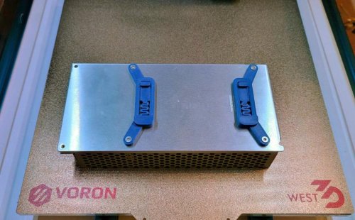
RS PSU DIN Brackets
MeanWell RS PSU Bracket
Overview
DIN brackets for MeanWell RS series PSUs (bolt holes 80mm center-to-center), edited from MarcPot's UHP PSU Bracket.
CAD file included.
BOM
4x M3x8 FHCS
OR
4x M3x6 SHCS Printing instructions
Normal Voron print settings.
Questions
Reach me in Voron's Discord @aTinyShellScript#3121 if you have any questions.
Images
56 downloads
(0 reviews)0 comments
Submitted