-
TeamFDM.com is an UNOFFICIAL companion site for the DIY Voron 3D printer community. For official docs and final source of truth, visit the Official Voron Discord or the Voron Github
Printable Voron User Mods
Voron User Mods, or "UserMods", are a collection of community created and Team FDM curated modification for Voron Printers. All of these mods are available on the VoronUsers Github repo and unless otherwise specified follow the Voron communities GPL3.0 Licensing. Use any Mods at your own risk, if you make modification please share them on the VoronUsers repo.
Mod Authors: Have a Voron mod? Upload it at TeamFDM.com and let us know you're the author. We will ensure you can update and curate your files for more feedback! Please include tags for what Voron, or extruder your mod is compatible with.
654 files
-

C17 EXT CARTRIDGE
C17 -EXT-CARTRIDGE, HEPA Carbon filter
The C17-EXT-CARTRIDGE is designed to be used with the C17-EXT HEPA Carbon filter.
This is a first publication, although all parts has been tested, there may be errors do not hesitate to contact me.
Assembly Manual
BOMs
The list of parts is described in the manual.
HEPA 13 Filter
Use HEPA 13 filters from 10mm to 18mm thick. The best is to find a HEPA 13 filter for vacuum cleaner and cut it with a cutter. The references change according to the country.
I tested this one after cutting:
The best but I do not find the reference in other countries: Amazon.fr
Aliexpress 1
Aliexpress 2
Carbon
WARNING : Although the C17-EXT does not return treated air to the printer enclosure, use Acid-free Activated Carbon (Coconuts for example : amazon) !
Credits
The C17-EXT Activated Carbon Filter was modelled in Fusion 360.
Contributing
A complaint is a gift. Please, help me to improve the C17-EXT-CARTRIDGE !
License
Distributed under GNU General Public License version 3.0 (GPLv3)
Contact
Discord: OboMaker3D#0669 - ()
Acknowledgements
The Voron Dev Team
30 downloads
- OboMaker3D
- v2.4
- (and 2 more)
(0 reviews)0 comments
Submitted
-
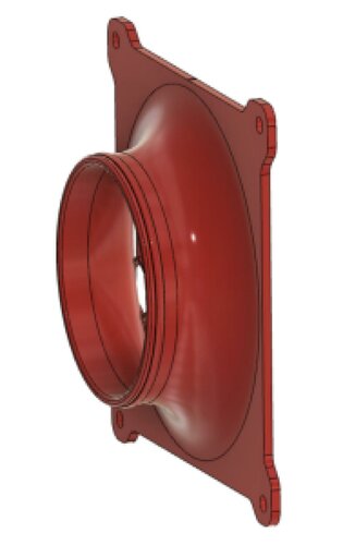
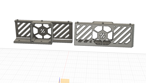
C17 EXT
C17 -EXT, External HEPA Carbon filter
The C17-EXT filter replaces the standard filter of the Voron 2.4 and to add one on the Switchwire . It has a 120mm fan and can use the C17-EXT-Cartridge filter (HEPA 13 and Carbon) or commercial HEPA Carbon filters.
This is a first publication, although all parts has been tested, there may be errors do not hesitate to contact me.
2 configurations
With adapter for standard back panel Voron
With specific back panel
For the Switchwire model only configuration 2 is possible.
2 options to replace the grid
Assembly Manual
BOMs
The list of parts is described in the manual according to the chosen configuration.
Fan
For the 120mm fan, follow the recommendations in the documentation. 3 models:
Efficient but noisy, the best choice (4000 rpm) : Aquatuning Alphacool 24810 ES (tested) Less powerful but quieter (3000 rpm) : Noctua NF-F12 iPPC 3000 PWM (tested, acceptable for commercial cartridges) Less powerful but quieter (3000 rpm) : Sunon MEC0251V1-000U-A99 (Not tested) If you find other models at 4000 rpm, please send me the references.
Filter cartridge
Two possibilities :
Using the C17-EXT-CARTRIDGE Use a commercial cartridge : Alveo3D Credits
The C17-EXT Activated Carbon Filter was modelled in Fusion 360.
Contributing
A complaint is a gift. Please, help me to improve the C17-EXT filter !
License
Distributed under GNU General Public License version 3.0 (GPLv3)
Contact
Discord: OboMaker3D#0669 - ()
Acknowledgements
The Voron Dev Team
342 downloads
- OboMaker3D
- v2.4
- (and 2 more)
(0 reviews)0 comments
Submitted
-
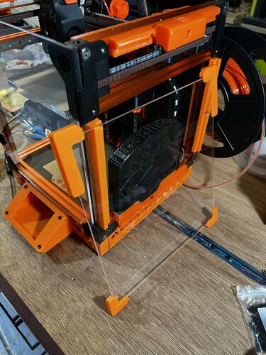
TipTophat
TipTophat
TipTophat is an alternative Tophat for the Voron v0.1 which uses the BOM panels. It provides 30mm in additional height as well as better access via the additional door. It places the side panels fully virtically to make the tophat square. It also comes with hinges that can be used with the Tophat hinge mod.
For the bleeding edge releases, see my development repo
Printing:
Use the Voron defaults and print in ABS. I have successfully printed the main body part(s) using 0.5mm layer width and 0.25mm layer height with 25% infill. This reduces both the time to print and the amount of filament used The parts are orientated correctly in the STLs If using the rear hing, print the appropriate Hinge_panel_left and Hinge_panel_right from Tophat hinge mod There is the choice of printing the whole body using the Unibody if you have a printer with a print bed of at least 238x238mm. Otherwise, you can print the separate quarters on a printer with at least 119x119mm printer bed. So they can be printed on a Voron v0, but it will be tight!
BOM:
Original BOM panels (panels of 2.5mm and 3.0mm have been tested) 28x M3x8mm** SHCS/BHCS (2x door frame hinge, 4x rear hinge (optional), 18x panel connectors, 4x tophat pins (optional)) 1x M3x12mm SHCS/BHCS (door hinge) 1x M3x25mm SHCS/BHCS (door hinge) 28x Brass heat inserts (2x door frame hinge, 4x rear hinge (optional), 18x panel connectors, 4x tophat pins (optional)) 2x 6x3mm Neodymium magnets VHB tape ** If your panels are 3mm in depth you will need to substitute 4x M3x8mm screws for 4x M3x(10 or 12)mm screws for the four mid connectors
Assembly:
Note: These instructions use directions based on the tophat in front of you being upside down with the back facing away from you and the front in front of you. Once you place the tophat on the printer, instruction directions are as you look at the printer from the front.
Building the frame and inserting the panels:
Place brass heat inserts into all the holes you are going to use. This is likely to be everything apart from the top 4 holes. Those top 4 holes are if you use the stock style pins to locate the tophat on the printer instead of using hinges at the back.
If you are building using the unibody instead of the four quadrants, you need to arrange the four quadrants with Q1 at the back left, Q2 back right, Q3 front left, Q4 front right. They need to be aligned correctly.
Place the top panel into the center of the bed and attach four connectors being very careful not to overtighten them, otherwise you can easily crack the print or the panels. It's better to have the connectors loose initially and tighten slightly until the panel doesn't move.
Now work from the left, to the back, to the right, using the side and bottom connectors for each panel.
Building the door:
The door connector takes a single 6x3mm Neodymium magnet. You should be able to press fit the magnet into the hole. If it's too loose, use a bit of superglue. If it's too tight, use a file of drill bit to widen it a little. Attach this to the frame.
Take the two door hinge parts and assemble. The screws go into plastic, so do not tighten. The hinges should be a little bit loose so that it moves cleanly without binding. This can be adjusted later.
Put VHB tape on the panel hinge.
With the hinge open, put the panel into place abutting the panel into the hinge and centered. Press the panel to the hinge with some pressure to ensure a good seal.
Screw the hinge to the side of the tophat frame. There is adjustment available here for later if there are issues with the door opening/closing or being askew.
If you are going to use the hinged tophat, screw the hinge parts to the back of the tophat frame. You should also fit the hinge parts to the printer.
If you are using the standard locator pins, screw those in.
Put the tophat onto the printer and screw the rear hinges together if you are using them. Note: The hinge holes are deliberately oversized to allow for different tolerances and spacing for the tophat to sit well on the printer.
Hanging the door:
Open the tophat door and close the main printer door. Now close the tophat door and check that it does not hit the main door. If it does there are a few adjustments that can be made later:
Adding the handle:
Take the door handle and the second magnet. With the tophat door closed, put the magnet against the frame magnet to get the correct orientation (use a marker pen on the magnet if it helps).
Maintaining the correct orientation place the magnet into one of the holes in the foot of the handle:
Place VHB tape over both of the handles feet:
With the tophat door closed, align the handle with the magnet at the top opposite the magnet in the frame and keeping the handle straight press it onto the door. If it's not quite right, it should be fairly easy to carefully, and slowly, remove the handle and do it again.
You can adjust the frame mount from the inside screws to change the fitting of the hinge. You can also tighten and loosen the hinge screws to lower and raise the door panel. If none of that works, unscrew the door hinge and take the hinge tophat door off. You can usually remove the hinge from the door, by very slowly pulling the hinge from the door panel, being careful not to snap the hinge or crack the panel. You can then redo the hanging steps for a better fit.
Changelog:
2022-07-22 Updated Body Quarters and STEP file199 downloads
(0 reviews)0 comments
Submitted
-
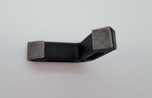
Handle
V2.4 Handle
Carrying handle for Voron 2.4 with 6mm clearance for panel clamping. The design was heavily inspired by https://github.com/yanyixiang/Voron/tree/main/舒服坚固的手把BY_路易斯亚细亚.
The handle is mounted on 2020 aluminium extrusions with 5 T-nuts. It should also fit on Trident and Voron 1.8.
Printing
default Voron print settings no supports needed use accent color for middle part
BOM
Size Qty M3x12 SHCS 3 M5x16 BHCS 5 M5 T-Nut 5 M3 heat set inserts 3
Assembly instructions
put heat set inserts in inner handle part
put T-nuts in aluminium extrusion (2 T-nuts in top slot, 3 T-nuts in side slot, coarsely adjust hole distances)
attach inner handle part to top side of the extrusion
attach middle and outer handle part to the side of the extrusion; do not tighten M5 screws yet
align parts and put in M3 screws; tighten all screws
580 downloads
-
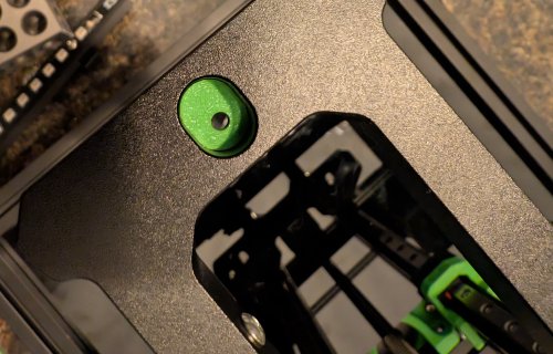
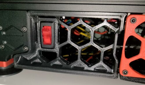
SideSkirtPowerSwitch
Side Skirt Power Switch
A mount for the GSW-42 rocker switch in the skirt element to allow easy access to a power switch without reaching behind the printer and trying to find it by touch. Can be substituted with GSW-41 if you don't want it to glow red when turned on.
Parts Required
(1) GSW-42 illuminated rocker switch Some mains wire Spade crimp connectors Butt crimp connectors Printing
Print as is for the88 downloads
(0 reviews)0 comments
Submitted
-
(0 reviews)
0 comments
Submitted
-
v0.1 V0.1 Magnetic Panel conversion
Converts the current Voron v0.1 panel mounting parts into easily removeable magnetic mounts. Perfect for switching between ABS/PLA without the hassle of unscrewing everytime.
Mounts using the basic m3x8 hardware that the original parts mounted with.
Included are the files for a spacer to fill the gap between the frame and the panels to help with heat loss, this is not needed but will help. I have installed some 12mmx6mm adhesive draft excluder found easily on amazon. You will need to print 8 of each "part 1" and "part 2" to fit each side, they will not totally fill the gap, there is a small space left on the top and bottom to allow gripping the panel to remove it.
Required hardware:
16x m3x8 (original hardware)
16x m3 nut (original hardware)
16x 8mmx2mm neodymium magnets (You can source easy enough, but here is a link to the ones i have used from UK Amazon; https://www.amazon.co.uk/Magnet-Expert%C2%AE-8mm-thick-Neodymium/dp/B007JTL25M/ref=sr_1_2?crid=VG4LDUUBDICR&keywords=8mmx2mm+magnet&qid=1647471673&sprefix=8mmx2mm+magnet%2Caps%2C48&sr=8-2 )
Optional hardware:
2m 6mm thick adhesive draft excluder
32x m3x8
32x m3 nut
3,281 downloads
-
Handle and Nevermore mount to magnetic panels by bravefruitcake
Here's some modified inserts to the V0.1 magnetic panels design by bravefruitcake, I've made a single filler piece with option for single screw mounting, optionally a filler that has built in handles, and a filler that lets a nevermore filter be magnetically mounted with a magnet power connector. Turn it on/off by snapping it on / off.
Also a strong magnetic rear panel mount.
Magnetic electric connector was from aliexpress 'Magnetic Connector 2 Pole Pogopin Male Female 2A Spring Loaded Pogo Pin Waterproof Pad DC Power Charging Connector'
475 downloads
-
Trident Skirt Lights
BOM
Part NO. Qty LCSC Conn_01x03 2 C131339 WS2812-2020 12 C965555 Assembly
Order the pcb at e.g. pcbway or jlcpcb (you need two for one printer) Order the parts at e.g. lcsc Print the new skirts (You WILL need supports) Print the new logo inserts (You WILL need supports) in the meantime, assemble the pcb Push in the new logo inserts in your skirts Push the PCB into the logo insert, no additional fastening required Wire up the pcbs to your controller Add them as normal neopixels to your config [neopixel my_skirts] pin: YOUR_NEOPIXEL_PIN chain_count: 24 initial_RED: 1.0 https://github.com/Gi7mo/TridentSkirtLights/raw/main/Images/Assembly.png https://github.com/Gi7mo/TridentSkirtLights/raw/main/Images/trident-skirt-lights.gif Notes
This project does not come with any warranty, if you choose to build/use one, you are doing this at your own risk!
198 downloads
-
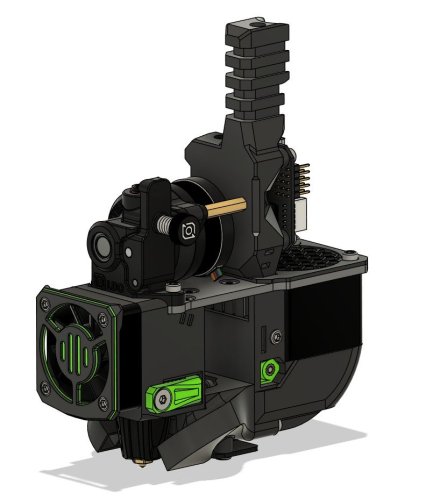
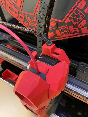
EBB42-Stealthburner-CW1-Mount
ebb42 mount for cw1 nema17 pancake with umbilical strain relief
Decided to go to canbus umbilical for my stealthburner on cw1 and remove both x and y cable chains. As the ebb42 is a new product there had been no mounts that have been released at that time so i came up with this design. The mount sits comfortably on the rear of my extruder nema17 pancake motor and spaces the ebb42 nicely away from the rear of the motor, the m3 motor screws i have are slightly to long so i used spacers on top of the ebb42 to counteract this, also i used a cable strain relief to protect the 4 wires to the ebb42 which the dimentions are 5mm hole, 28mm length, diameter 11.8mm, slot diameter 7.55mm x2.1mm which goes into a little slide in wedge to hold into place and also used expandable braided sleeving size 3-9mm which protects the wires and sits nice and snug in the strain relief.
i also modified the original stealthburner cw1 pcb cover by Demosth to fit with this mount (https://www.teamfdm.com/files/file/535-stealthburner-cw1-pcb-cover).
433 downloads
- stealthburner
- ebb42
- (and 3 more)
-
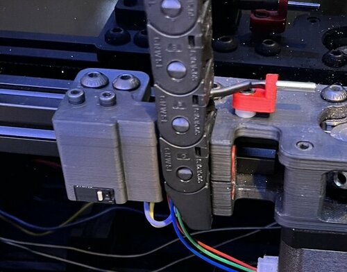
Y Endstop Adjustable Gantry Mount
After installing the btt ebb42 canbus and removing the x y cable chains i tried the ab motor mount y endstop mod but found it moved y max forward about 1mm which affected my euclid gantry mount deploy and stowing so i designed an adjustable gantry mounted y endstop with jst 2 pin socket connection and the wires go easily through the z cable chain to the electronics compartment, the mount fixes to the rear gantry via 2x M5 screws with T nuts and has 2 M3 heatsets installed to mount the endstop holder which uses the normal omron endstop switch fitted with standard bom 2x M2x10 self tapping screws.
Printed using standard voron print spec
253 downloads
(0 reviews)0 comments
Submitted
-
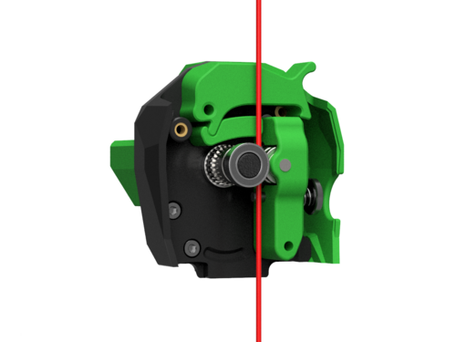
Galileo extruder for stealthBurner
https://github.com/JaredC01/Galileo
BOM
Galileo componants 4x M3X25 3x M3X16mm 8x heat brass insert (BOM insert)
Appreciate my work ?
buy me a coffee https://www.paypal.com/donate/?hosted_button_id=9EL8CEDVY28DA thank you and happy printing
2,478 downloads
-
Stealtburner with LGX PCB mount
Fitted the Bondtech LGX extruder to the Stealthburner. Could not find a mount and designed this. Use at your own discretion. Change and mod as you wish and pay back to the community. Hope someone finds this useful. Step file included in zip. Uses M3 x D5 x L4 brass inserts for attaching the PCB. Printed in ABS 0.2mm resolution 18% infill. Print with supports enabled.
207 downloads
(0 reviews)0 comments
Submitted
-
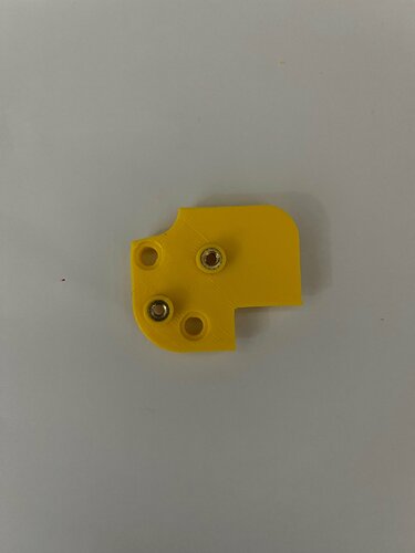
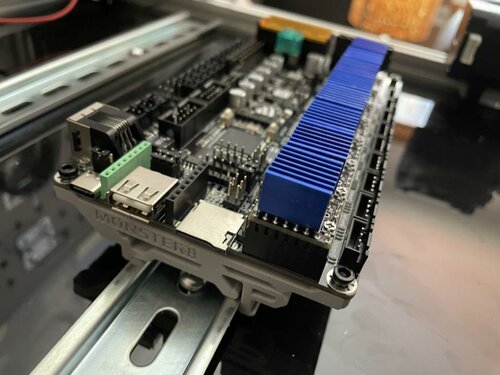
Monster8 Heatsert Mount
Monster8 DIN clips (with heatset inserts)
There's a DIN clip mount from Makerbase but I don't like it because it's too big to print on the bed of a V0 and I hate threading small bolts into plastic.
So I made this version. It works!
58 downloads
(0 reviews)0 comments
Submitted
-
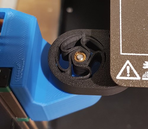
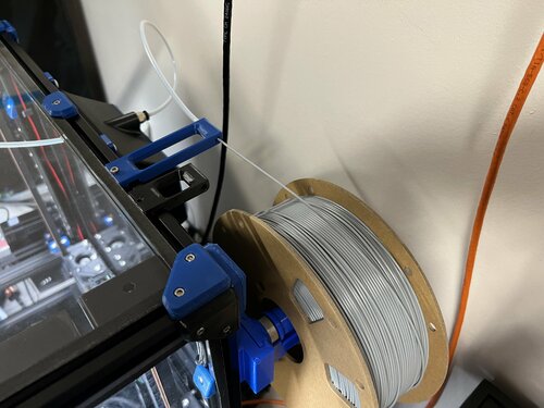
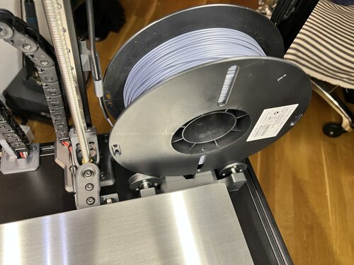
Enlongated Bowden Retainer (for use with longer spool holders)
Simply elongated the stock bowden retainer to be more inline with the roller spool holders like the one below.
This adds 35mm to the overall length of the retainer.
118 downloads
(0 reviews)0 comments
Updated
-
Z-Motor cover Trident
2 Parts
Mounts snap in place
0.2 layer Height 20% infil i hope this help
877 downloads
-
V6 Bowden Head fan shroud
I was dealing with serious jamming in the hotend every print.
On my research I noticed almost every picture of the V6 hotend shows a fan shroud that forces the air to get pushed trough the cooling fins.
It seems not necessary on the Voron design because there is not a lot of space where the air can go, but rememeber: air is like any other fluid, getting forced it always wants to get the way wich has less resistance and in this case it is beside the cooler and nothing of them will go inside the cooling fins. especialy that tiny amount of air from an 30mm fan.
For me it works well, getting rid of the jamming by this little mod 🙂
+ getting sure you have added thermal compound paste on heatbreak/cooler
1 download
(0 reviews)0 comments
Submitted
-
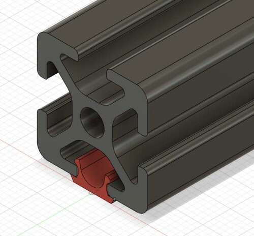
20x20mm Profile Covers
20x20mm, slot 6 Profile Covers
Please find here my mod for variable profile covers for 20x20 construction profiles with 6mm slot.
Printing
Printing successful with standard VORON settings.
For adjusting the length of the profiles you can scale the *.stl file in your slicer in y-direction after import and before positioning (rotating/placement) on your print bed. Please find the following example on how to do so for SuperSlicer:
Sequence: Deactivate linked scaling with click on lock symbol, Lock symbol status (
1,023 downloads
- chri.kai.in
- v1.8
- (and 3 more)
(0 reviews)0 comments
Updated
-
MKS CANable Pro Mount
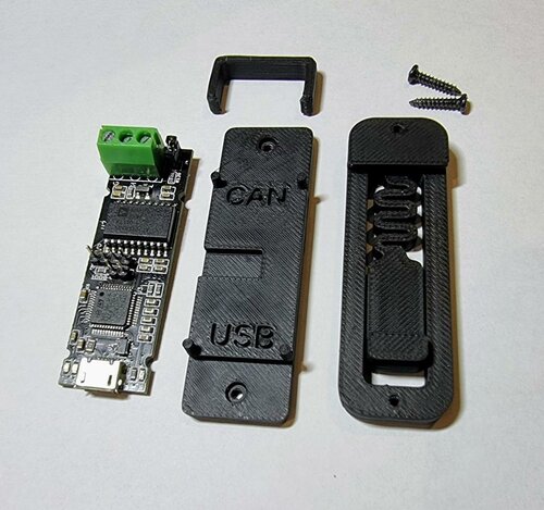
MKS CANable Pro DIN rail mount
This mod is to mount the MKS CANable Pro to a standard 35mm DIN rail.
The CANable Pro is held from moving along its longest axis by the 4 locating pins and held onto the mount by a clip over the CAN transceiver holding it in place. The board can only mount one way due to the header pins and for any doubt the output directions are labelled on the mount.
To print you need
canable_pro_clip.stl canable_pro_mount.stl pcb_din_clip.stl (credits to the Voron team for making this) And 2*M2x10 self tapping screws or if you don't want one of the screws poking out a shorter one (5-7mm) or just cut the end off with snips.
To assemble, screw the mount onto the PCB DIN clip and then place the board on the mount with the outputs aligned in direction shown on the mount. It should sit flush as shown below and then the clip slips over the top and locates into 2 small indents.
Enjoy!
Thanks to @Micko SE
288 downloads
(0 reviews)0 comments
Submitted
-
Trident Internal Spool Holder
Important Note:
This mod works on Trident 300 and 350 builds ONLY. 250 build simply has no space needed to accomodate the holder and the spool. Sliding 8mm linear guides allows for adjustable spool width. Supported spool size is 200mm in diameter and up to max 75mm wide, typical for spools up to 1kg - 1.2kg.
Changelog
08.05.2022. Initial Release
20.05.2022. Added new PTFE guide with tilted opening that guides the PTFE slightly to the left to prevent sharp bends. Just one lower guide is recommended now with this new top guide.
Why?
Over the years i've been getting nicer prints and almost 100% eliminated wet filament ooze by placing the filament spool inside of enclosed chamber. Since my printers work almost 24/7, chambers are always hot enough to keep the filament dry and produce perfect prints.
Print Setup
All parts are printed without supports. Recommended material is ABS/ASA. Recommended perimeter count is 4 and 5 top/bottom layers with infil from 30% . All parts in STL already have correct orientation, just import and print.
STL File naming:
...x2.stl simply means you need to print 2 parts BOM
8x F688zz Flange Radial Ball Bearing 8 x 16mm 2x 8x100mm linear guide 12x M3x4mm countersunk screws (M3x6 BHCS or SHCS screws can be used as well) 18x M3x4x5 Brass Heat Inserts 2x M5x16mm 2x M5x10mm 4x M5 T-Nut (Regular or Hammerhead) 6x M3x8mm Images
958 downloads
-
Lgx Lite Side Can
LGX Lite CAN Side Mount (Huvud/SHT42)
Side mount for CAN toolhead boards with NEMA 17 sizes such as Huvud and FLY-SHT42.
You will need two M3 square nuts that should have come with the LGX Lite to put into the side holes for mounting.
I am using this on my Voron 2.4 with Mrgl-Mrgl's LGX Lite Mount for the extruder.
BOM
4x M3 Square Nuts (Included with LGX Lite) 4x M3 Heat Sets (Standard Voron Spec) 2x M3x6 BHCS to mount through to LGX Lite holes 4x M3x6 SHCS for board mounting (or whatever is suitable for your board)65 downloads
(0 reviews)0 comments
Submitted
-
Toolhead Pcb To Can
Toolhead PCB To CAN Mounting Adaptor
Simple mount to convert Afterburner Toolhead Board mount spacing to the spacing for popular CAN toolhead boards like Huvud and FLY-SHT42.
The assumption is that you have created an evenly spaced pair of holes to mount to with spacing for the afterburner toolhead PCB (version 4.0 and below). For example, on my 2.4 with a Galileo Stealthburner I am using hartk's Galileo Body. If you need spacers, they should be easy enough to create in Tinkercad or just by overlaying cylinders in your slicer.
BOM
4x M3 Heat Sets (Standard Voron Spec) 2x M3x6 BHCS to mount through to PCB holes 4x M3x6 SHCS for board mounting (or whatever is suitable for your board)47 downloads
-
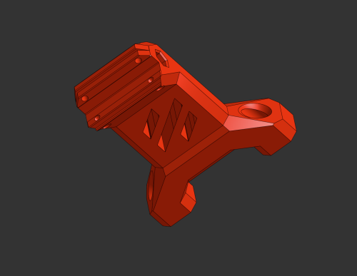
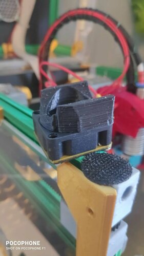
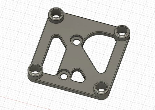
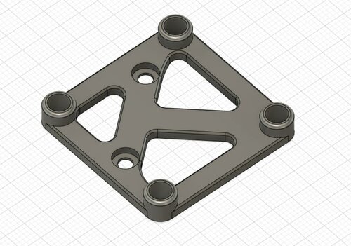
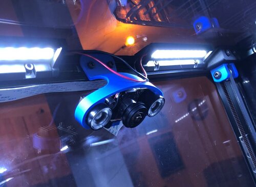
Mount For Electreeks Camera
This is a simple mount for the currently popular Electreeks Camera (and the similar models of other brands). It is supposed to be mounted on one of the top Aluminium Profiles of the Voron 2.4 (see picture) maybe it also fits on other printers with closed frame and 20x20 profiles. You need two M3x8 Screws and two M3 slot stones to mount it.
40 downloads
(0 reviews)0 comments
Submitted
-
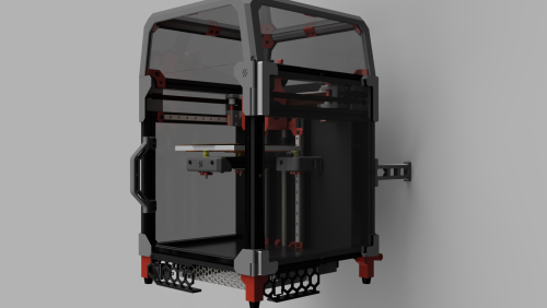
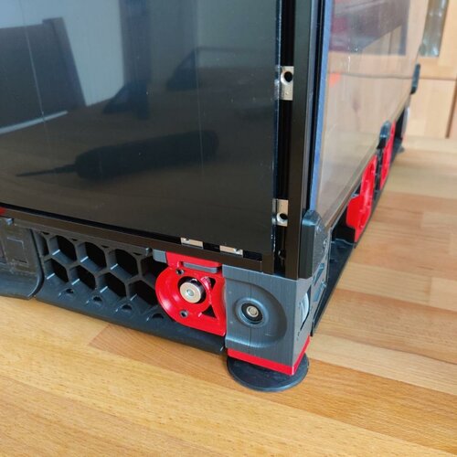
RockNRoll
RockNRoll - Rockers for Voron V2.4
This mod is intended to make access to the electronics compartment easier by enabling the printer to be rolled on its back without damaging cables or the exhaust system. The rockers are mounted on the vertical extrusions in the back replacing the panel corners. Additionally they are braced against the horizontal back extrusion. The mod is designed for and tested with a 350mm V2.4, but it might work with a V1 or Trident as well. Due to their higher center of gravity V1 and Trident might need additional feet higher up. If you tried this mod on a V1 or trident, let me know how it went on discord.
Gallery:
To give you an example how this works, take a look at these pictures:
Hardware needed:
pcs. name 4 M5x10 BHCS 4 M3x12 SHCS 2 M3x20 SHCS 4 M5 T-nut 4 M3 T-nut 2 M3 Threaded Insert As all these are in the BOM of a V2.4 it is highly likely you can build this mod with leftovers from your printer.
Printing:
Parts:
To start off you need to print these parts:
1x rocker_right 1x rocker_left 1x rocker_right_brace 1x rocker_left_brace If you use thicker panels or foam tape than the default 4mm, there is a 6mm version in a subfolder.
For additional support you can swap the base plates of the rubber feet to the ones from this mod. If you are building a 2.4r2 print these:
1x base_plate_a_r2 1x base_plate_b_r2 If you still have an 2.4r1 build you therefor need:
1x base_plate_right_r1 1x base_plate_left_r1 Print Settings:
This mod needs rigidity and stiffness. Based on the Voron recommendations for structural printer parts these settings are recommended:
0.4mm Nozzle 5 Perimeters 40% Infill 10 top and bottom Layers The test prints in the pictures are done with Formfutura rTitan ABS.
Support:
All the STLs are oriented correctly. The rockers themselves have overhangs where the backpanel is supposed to sit. Don't forget to remove the three support tabs integrated into the 3D model before mounting:
Assembly:
Threaded Inserts:
Start with melting the M3 threaded inserts into the braces:
Mounting the Braces:
Remove the bottom corner panel clips of the back panel and insert the T-nuts. Put two M5 T-nuts into each vertical extrusion and two M3 T-nuts on each side of the horizontal extrusion. Put the braces roughly in place and screw them in lightly with two M3x12 SHCS bolts each.
Mounting the Rockers:
Make sure the T-nuts line up with the holes in the rockers and mount the rockers on their braces. They should slot right in. Bolt rocker and brace together with a M3x20 SHCS bolt before mounting the rocker on the vertical extrusion with two M5x10 BHCS bolts. Once every bolt is in place, tighten them all up.
Optional: Mounting the Base Plates:
To increase the support of the rockers you can swap out two of the original base plates of the rubber feet with the ones of this mod. They slot into the rockers tip and support it while tilting. There are STLs available for both 2.4r1 and 2.4r2. The mounting example shows the r1 version, mounting the r2 version is similar.
Start with playing your favorite Elvis song and rocking and rolling the printer on its back for the first time. Remove the rubber feet and the stock base plates:
Swap the M5 nut of the stock base plate to the new one and slot the fork tips of the new base plate into the rocker. Then screw everything back together:
3,863 downloads
-
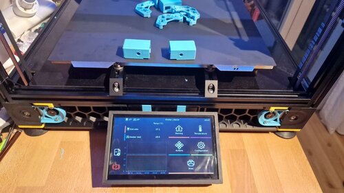
BTT PiTFT
Overview:
This mod adds a mount for the BigTreeTech PiTFT. Currently the mod works for the PiTFT70, but im planning on adding a 5
412 downloads
- Mac10goesBRRRT
- v2.4
- (and 1 more)
(0 reviews)0 comments
Submitted
-
Most Actively Discussed Mods
-
Hottest Files!