-
TeamFDM.com is an UNOFFICIAL companion site for the DIY Voron 3D printer community. For official docs and final source of truth, visit the Official Voron Discord or the Voron Github
Printable Voron User Mods
Voron User Mods, or "UserMods", are a collection of community created and Team FDM curated modification for Voron Printers. All of these mods are available on the VoronUsers Github repo and unless otherwise specified follow the Voron communities GPL3.0 Licensing. Use any Mods at your own risk, if you make modification please share them on the VoronUsers repo.
Mod Authors: Have a Voron mod? Upload it at TeamFDM.com and let us know you're the author. We will ensure you can update and curate your files for more feedback! Please include tags for what Voron, or extruder your mod is compatible with.
660 files
-

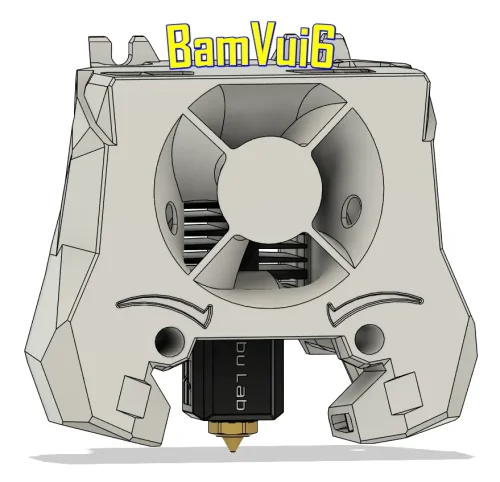
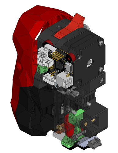
BamVui6 - Stealth Burner Bambulab Clone Hotend Mount
This mod allows you to mount the Bambulab clone hotend with a V6 nozzle onto the Stealth Burner.
292 downloads
(0 reviews)0 comments
Updated
-
(0 reviews)
0 comments
Updated
-
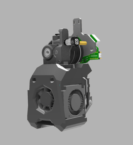
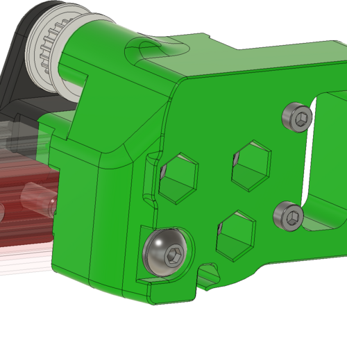
Printhead | Amended Voron Tap + Rapido Hotend + Orbiter 2.0 + EBB36
Printhead | Amended Voron Tap + Rapid + Orbiter 2.0 + EBB36
Using 2x: 4010 radial fan + 3010 fan.
1,760 downloads
-
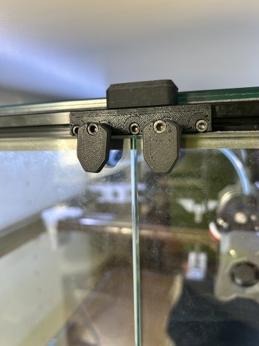
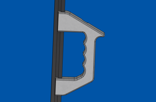
Door handle | 3 Parts only - no magnets / tape
I wanted a more accessible door-closing mechanism for my glass doors, which provides some pressure to seal the door.
It uses a simple half-helix. You might have to amend the height for your specific panel thickness.
269 downloads
-
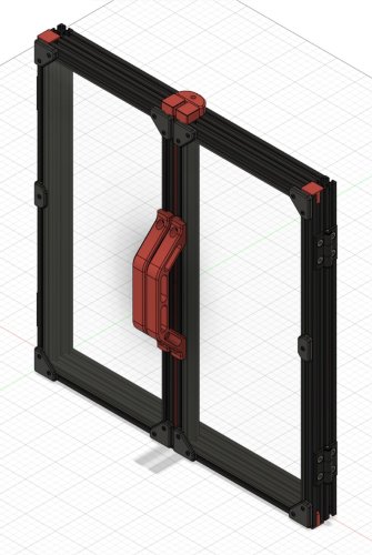
Beefcake Handle Version 2 - Extra Heavy Duty Handle for Extra Heavy Vorons
My printer weighs close to 100lbs and half of that is glass panels. I don't trust current handle designs for that kind of weight but I needed something to make my printer movable. Each one needs 2 screws: 2 x m4-18mm and 2 x m4 t-nuts.
The handle is designed to load the extrusions along the inserted ridges. The screws are mostly there to keep it fully inserted; in fact, the handle clips on the frame and hold there without the screws!
These handles will make it possible for two people to firmly hold the printer and carry it. STL needs to be mirrored to make a proper pair and 2 pairs needed for a full set.
Hinge Clarence:
Version 1 installed (v2 looks the same)
309 downloads
-
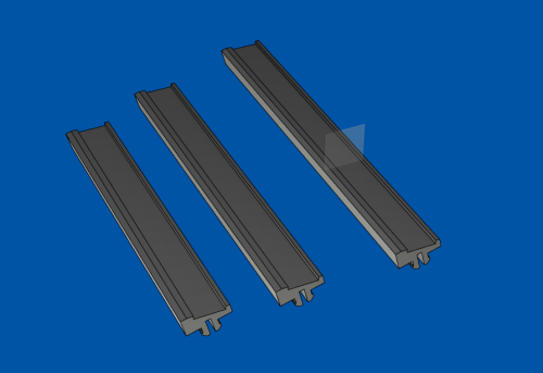
LED clipping rails for 250 300 and 350 frames
These are designed to clip into 2020 extrusions and have a 12mm trough to accommodate 11mm LED strips of the most generic kind. a set of 3 is required to cover your horizontal rails. They clip pretty hard. I suggest printing just 1; interrupt the print after the first clip is done and test on your extrusions to make sure it clips but not unreasonably hard. You can use "horizontal expansion" setting in your slicer to adjst the fit. Print them standing up and with a wall width of 0.5mm: this is required for the plastic to comply when pushed in the slot.
** This is meant as a permanent fixture: be careful when testing as I was only able to remove them by sliding off the end. It would suck to have to disassemble your frame **
New shaded version here: Shaded LED rails
368 downloads
(1 review)0 comments
Updated
-
JetPack | Carbon Filter + HEPA incl. 12032 Radial Fan
Created an alternative Carbon Filter using a 12032 Radial Fan.
The Carbon filter is magnetically interchangeable.
Additionally, you might install a HEPA-Filter (from a S6 vacuum robot)
Printed in PC and ABS / no support needed / 0.6 nozzle
As a filter I use Coconut Active Carbon.
Any ideas for improvements? Please leave comment 😉
174 downloads
(0 reviews)0 comments
Updated
-
v2.4 300 Doors
This is just for the 300mm v2, but it should scale well for other sizes. The vertical extrusions are the same length as the verticals for the printer. The horizontal extrusions are the half width of the printer minus 22. For the 300 this is 420/2 - 22 which is where the 188 comes from.
BOM:
4 HFSB5-2020-480-LCH-RCH 4 HFSB5-2020-188-TPW 4 HHPBSN5 18 SHCS M3x8 16 FHCS M5x8 4 BHCS M5x10 4 M5 T-Nuts 9 M3 T-Nuts 2 Acrylic Pannels 202 x 454 (slightly different than stock) 18 3x6 Magnets 3mm Foam Tape Print List:
6 2020 Profile Corner Endcap 2 2020 Profile Corner Endcap with 6x3 Magnet 2 Handles 1 Top Latch 2 480mm Door Magnetic Latch 1 2 480mm Door Magnetic Latch 2 2 480mm Door Magnetic Latch 3 8 6.5mm Corner Panel Clip 8 6.5mm Midspan Panel Clip
477 downloads
(0 reviews)0 comments
Updated
-
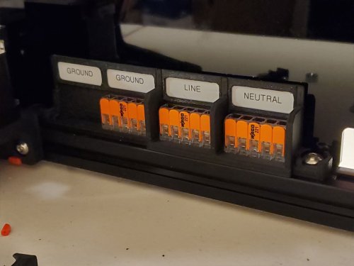
221-415 WAGO Mount with Labels (REMIX)
These are some WAGO 221-415 holders, which are just a remix of the WAGO holders in the Voron Github (here).
Since these models are designed to work with electrical components (WAGO blocks), use these models at your own risk.
The stock 2020 rail WAGO mounts included in the official Voron files fit the WAGO 221-415 blocks perfectly. So well that I had to break the first one I printed to remove the precious WAGO's, when I remixed the design, and needed them out, to test it. The models here are just modified from the original Voron design, I did not change the parts of the models which hold the WAGO blocks (since that works well).
There are really only 3 changes from the original design incorporated into this remix. The first change was to create a 4x415 block (as well as a 2x415 block). Then I added some taller walls between the WAGO's, and label holders. The walls are there to give connections a bit of extra protection from getting bumped. The last change is the label holders, which are designed to be used with Brother P-Touch 12mm labels, but other labels would also work if they can be made to fit. Since the labels may not stick well to a bumpy printed surface, they are retained by small frames which will slide over them. A dab of superglue could be used to hold the frames if there are no plans to change the labels.
There are three sizes and the label frames are the same between them (just print as many frames as needed). The design shown in the pics is the one I used in my Voron 2.4 R2 build, and is slightly different that the models here. But I only updated the design slightly, so that all the WAGO's have individual frames and higher walls between them in the models posted here (compared to the model I used which has two WAGO's sharing one label frame).
The STEP file is included for easy remixing.
You can check out some of my other projects in progress (and completed projects as well), on my blog here. I'm still building my Voron 2.4 R2 and am working on a few other designs related to it. If you want to help me get to my first spool of Prusament, you can add a make over at Printables for this design.
430 downloads
(0 reviews)0 comments
Updated
-
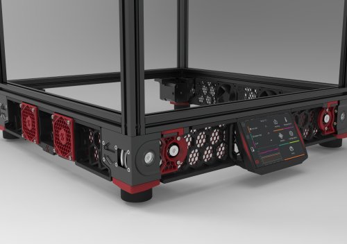
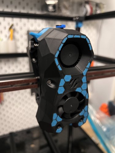
Hex mesh skirts for voron 2.4, with matching fan grills and Z motor covers.
Hex mesh skirts for Voron 2.4, with matching fan grills and Z motor covers. The skirts are obviously remixed versions of the default Voron designs. The fan grill and motor covers are my own creations.
The center, side, fan supports have been modified so that they fit onto the printer backwards. You will need to install one additional heat set insert into the front of the fan (4 total in the front), and add 3 to the back. Three m3x8 screws hold the fan into the support from the backside, and four m3x8 screws hold the fan grill onto the front.
Included is a model file for a 6020 fan blank. This blank will allow you to mount the grills on the side opposite that which has the fans, while maintaining the same appearance as the side with the fans.
For multi-color prints, just swap out your filament at the layer above the hex mesh.
I have included .stp files, to make it easier for anyone who would like to remix.
12,362 downloads
-
(0 reviews)
0 comments
Submitted
-
(0 reviews)
0 comments
Submitted
-
-
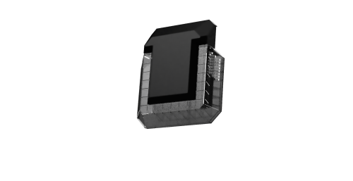
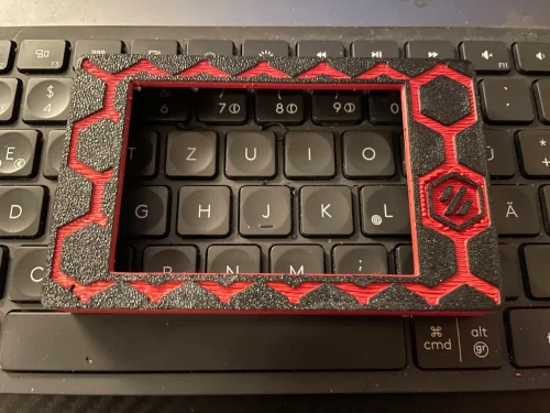
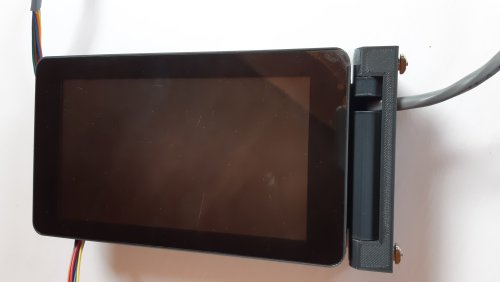
DRO Style, Side-Mounting, Housing for Official Raspberry Pi 7 inch Touchscreen
This is an "expert mod" and should only be attempted if you understand the risks involved, which include:
-ruining your printer's frame, which means starting over your project... The mod requires you to drill through your frame. I suppose the cable could be routed outside but, hey, in for a penny...
-dealing with RF interference on the usb lines which may produce hard to detect issues: The Raspberry Pi is going to be housed with the screen so the USB lines need to be passed back down in the cable to connect the main board and the webcam: care needs to be taken here to reduce RF interference so it involves wrapping wires in foil tape.
also, the actual print is challenging because it includes aspects of 'print-in-place' that require good temperature tuning to succeed: the cover is printed in place with the main case and need to be broken out with tools after printing. If you are good enough to drill your frame, I'm sure you'll figure out the print...
I doubt anyone will try this one but I'm putting it out there given the amount of work this was to perfect. So I could go on with details but I'll stop here. PM me if you want build this and have questions.
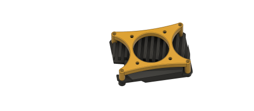
So for the uninitiated, a DRO is a computer you add to a machine tool to make it partly CNC and generally looks like this:
It is typically hanging around on the sides and most importantly, at eye level !
40mm x 10mm fan in fashionable brown 😉 snaps in tight
ADDITIONAL NOTES:
Wow, that's an honor, I hope you like it. Here is a bunch of extra info on that. did you look at the STL's ? what do you think of the print-in-place cover?
As it is now, the base piece is sized for my thick enclosure at 7mm. This can be adjusted:
Also, I did not test it yet because I'm waiting on parts to finish a bunch of peripheral stuff all at once when I put the printer out of commission. It should be next weekend. I'm pretty sure the Rpi will fit ok but I have a little doubt about the clearance between the fan and the pi's pins. I used drawings to figure out clearances but I may have did it a bit tight. The cover may need modifications but all the other parts are tested and working fine.
to separate the cover from the main body, you need to pry it from the inside from under the screw posts. if your print settings are just right, it pops off with moderate force. to do this, I placed the part in an open vice and pried with one of these:
drill size is 9/32" or 7mm or 7.5mm max. drill at high speed and low pressure to prevent sudden biting, take breaks to prevent melting of the drill guide
The cable I used is a leftover from industrial worksites. the passages are for a 7mm cable so anything smaller than that will work. you will need to splice usb cables somewhere in there so take care of adding shielding, especially where the cables pass near the z motors at the corner of the base
for the base: 2 x m3 t-nuts and 2 x m3-12 screws
for the arm and main body joints, 2 x m3-30 and 2 x m3-12
for the face: 4 x m3-8 and for the cover 2 x m3-12
also, the screen's included m2.5 brass posts are too long by almost 2mm and need to be replaced. -->testing needed but I got an assortment box:
https://www.amazon.ca/gp/product/B06XX28ZZR/ref=ppx_yo_dt_b_asin_title_o03_s00?ie=UTF8&psc=1
Finally got the time to get it working:
power management: I soldered on the monitor's PCB cause I had no space to plug on the header. I added 2 pairs of wires for the Pi and for the fan :
USB:
For cables, I just used 2 spare USB A-B cables from a dusty box. Try to get the thinnest possible wires that are shielded.
Here is a suitable choice for a spool of generic USB 2.0 shielded wire:
https://www.digikey.ca/en/products/detail/cnc-tech/2725-2828-BL-01000-A/6023708
Since the cable needed a splice in any case, I bought 'Type-A' USB connectors to make my own cable termination:
https://www.digikey.ca/en/products/detail/adam-tech/USB-AP-S-RA-SMT/9832307
Keep the wires as short as possible. I used a ferrule to join up the sheathings from both cables, which includes stainless steel, aluminum, copper, cotton and mylar... It can't be soldered !
Hot-Snot for that extra Chineseum touch also, I soldered a solid copper rod between the two connectors for strength. you can see it through the snot on the right side
As for the other ends of the cables, I just did a simple soldered splice with heat shrink: made them as short as possible, as straight as possible, and I introduced 1 turn between the data lines in the joint and shielded with foil tape.
RF shielding and hot-snot hider: it's just aluminum foil tape:
All working! looks awesome!
192 downloads
-
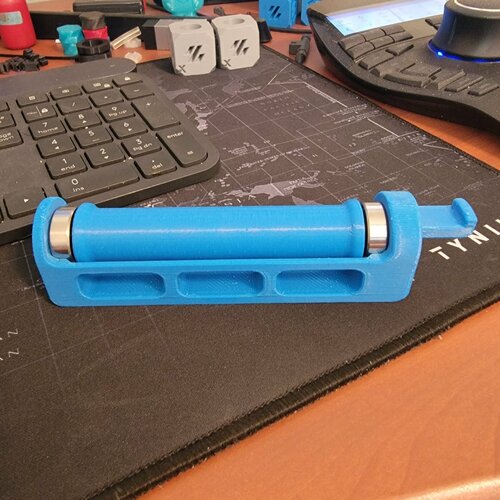
Roller Spool Holder for Switchwire
I designed this roller spool holder for the Switchwire after modifying and existing 2.4 roller spool holder to make it easier to print.
Roller (1 req'd) should be printed vertically. I chose gyroid infill as it doesn't cross over infill lines that've already been printed like cubic that can potentially knock the part off the print bed. Use standard Voron print specifications.
Pegs (2 req'd) for the ends should be printed vertically. I increased the perimeters to 6 so that I didn't need infill and also added a brim to further stabilize the parts during printing.
The Roller Holder (1 req'd) should be printed with the flat side down. You will need, at a minimum, supports for the hook and stub that mount into the Spool Holder Bracket. I used the default supports in SuperSlicer.
Bearings: Bearings are 8mm ID x 22mm OD x 7mm wide sealed ball bearings. Two required.
Spool Holder Bracket: This is the standard Voron Design spool holder bracket for the Switchwire. Print per Voron specifications.
823 downloads
- penatr8tor
- switchwire
- (and 2 more)
(0 reviews)0 comments
Updated
-
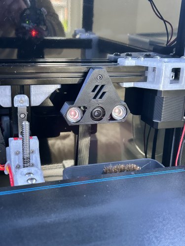
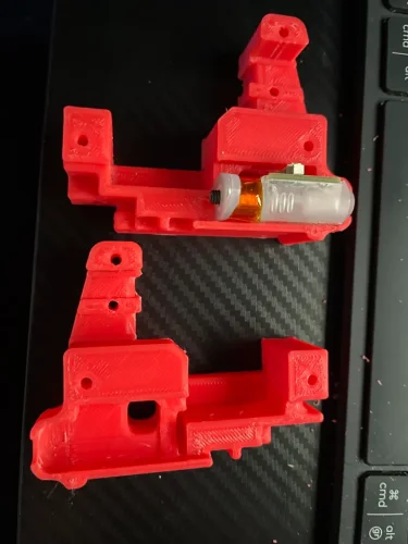
beacon CW1 Beacon drop-in mount
Made a drop in mount for anyone still using CW1. Not sure if it'll work with the CW2.
Requires the low profile beacon. The normal version will not work with this mount.
QTY: 2 - Brass heat insert from 2.4 BOM
My Beacon config
[beacon]
serial: [insert your address here]
x_offset: 0 # update with offset from nozzle on your machine
y_offset: 22.5 # update with offset from nozzle on your machine
backlash_comp: [change to whatever yours is]
mesh_main_direction: x
mesh_runs: 2
44 downloads
(0 reviews)0 comments
Updated
-
BTT CB1 Heatsink 30mm Fan Mount
I got some Heat issues on my CB1 so i desingt in Fusion 360 this Model
BOM
4 M3 Nuts
4 M3x12 screws to mount Fan on the Fan Mount
4 M3x20 screws to mount on CB1 and BTT M8P
41 downloads
(0 reviews)0 comments
Submitted
-
FYSETC Carbon Fiber Tube End Plugs and Rail Install Tools for the Voron 2.4 R2
These parts are designed to be used with a FYSETC Carbon Fiber X-Axis Tube, which I bought on sale at AliExpress for my Voron build, before realizing it would be a bit of a pain to assemble due to the design. These parts resolve most of the problems I expected to have, and went together well, when I built the XY joints and the X rail. I used the official models to help with the design and hole placements. Thanks to the Voron team for providing the design files and all their work in creating the Voron series of printers!
Before continuing, please note, use these parts at your own risk. They are by no means perfect and you can, if you wish remix this or use another method (STEP file is included). This worked for me and so I am posting it here, but I am still building my printer.
The parts include a model for an “plug” which holds three M5 locknuts and M5 washers, and two tools which are designed to assist with installing the MGN12 linear rail. The plugs stay in the final part.
Two plugs are needed and they can be interchanged between left and right sides of the rail. There are stops on the plugs, which I considered removing, however they help to keep them from going in too far during installation. I suggest printing one, and then testing it in the tube. If it is too tight, you can try calibrating the flow and then the horizontal expansion which will help get it to the correct size (the plugs should be 16.87mm in width). I printed them in PETG using a 0.6mm nozzle, 3 walls and 30% gyroid infill, since these should be robust. The plugs have holes designed within the parts, which are there to help fill up the areas around the nuts, since these areas need to be almost solid.
The tools are used by setting M3 locknuts in the pockets of the “A” tool, and then setting M4 washers on top (I used M4 instead of M3 since the M3 washers I have are too small to do much). Make sure the nuts fit snug but not tight, otherwise you will have a problem removing the tools.
I recommend doing a test before using the tool, by tightening down a few of the locknuts installed in the “A” tool, using some M3 screws, checking to see if doing so will cause the nuts to spin out. If they do spin out, DO NOT USE THE TOOL, since during installation there will not be a way to tighten the nuts down if they spin out. If the nuts do spin out in a test, then you can try adjusting the flow and horizontal expansion (if the holes are too large), or increase the strength of the part using more walls, more infill, higher temp, or use a different material. It is also possible that the nuts being used are different than the ones I used when designing this (the M3 locknuts I used were approx 5.42mm flat to flat, and the model is designed with 5.65mm flat to flat pockets).
Once tested, the “A” and “B” tools are then placed together, and both are then inserted into the tube and aligned with the holes for the linear rail. Note that the “B” model should have the groove facing the front of the tube where the rail will mount (this groove is there to allow the tool to pass by the screws when removed - see pics). If the tools go in too tightly, do not force them. Remove them, and either sand them down, or recalibrate flow and horizontal expansion for the material being used. Take the time to do this right, and if you don't feel this will work, please do not continue, since getting the nuts removed once installed will be a problem with or without a tool.
Once the tools are in place (and loaded with the locknuts and washers), the rail can be installed using M3x10mm screws (and M3x12mm screws on the holes that do not go through). I only printed one set, however if you want to print two sets, you can install screws on both ends of the rail at the same time, otherwise just do one side and then the other.
To remove the tools, use longer M3x12 screws in the holes that are not through holes, these will help to push the tool away from the nuts. I would start these longer screws with the “B” tool installed almost all the way, but remove the “B” tool before fully tightening the longer screws. If tightening down the M3x12 screws does not loosen the “A” tool enough to remove it, you can use a long (and thin) flat screwdriver, or even a folded over wire coat hanger to help pop it off the remaining nuts. It may also be easier to start with the innermost screws, remove the tools, reload and reposition, and then do the screws near the edges, if removing the tool is challenging.
Please refer to the pics to see how the tools work together, or ask a question in the comments.
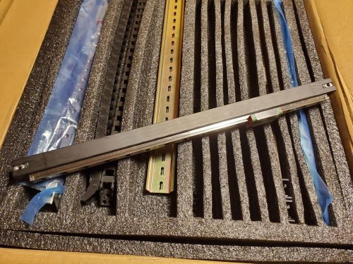
As for whether it's worth it to use the FYSETC CF tube, I'm not sure yet. I forgot to weigh it before assembly, so I don't know how much is being saved, but it does seem pretty robust and I'm sure its lighter than the aluminum extrusion. The pic showing the weight of 438g is just the tube, rail, screws, nuts, washers and plugs as shown in the pics, it does not include any other parts like the printed XY joints. In any case, this is not an endorsement of the FYSETC product, only some parts which may help to actually use it.
The STEP file is included for easy remixing.
You can find more info and pics for this thing at my blog here. I'm also documenting my Voron 2.4 R2 build here (but it's been a slow going process due to some other issues).
102 downloads
(0 reviews)0 comments
Submitted
-
Belt Clip Shim for the CHAOTICLAB CNC Tool-free XY-Axis Tensioner for Voron 2.4
I'm building a Voron 2.4 R2 and purchased the CHAOTICLAB CNC Tool-free XY-Axis Tensioner for Voron 2.4, which is a nicely made part (milled from aluminum) with a knob to adjust the tension of the XY belts. Mine did not ship with any belt clips, and I don't think they are typically included, so I first tried using the stock clips. However when I assembled my XY axis, I found that the 30mm screws used to hold the XY tensioner to the Z-blocks were 2mm too long. This is because the CHAOTICLAB XY tensioner has a thickness of 3mm where it connects to the 2020 extrusion, while the stock is 5mm thick. Because this 2mm difference affects the stack height for the Z-carriage mounts, I thought I should do something about it. The simplest way to address this is to thicken the lower Z-belt clip (which is 5.6mm thick) by 2mm, so that's what this part does.
I included a version which adds 2mm (7.6mm overall), and another which adds 1.9mm (7.5mm overall).
I'm still building my printer, so things may change, but this seems like such a simple thing I doubt there will be any issues.
119 downloads
(0 reviews)0 comments
Submitted
-
Stealtburner CW2 Main Body and Latch UM2 MOD
Makes it possible to use a UM2 lock to hold your Bowden Tube in place, often it can let go when loading your filament manually, this fixes that.
133 downloads
(0 reviews)0 comments
Submitted
-
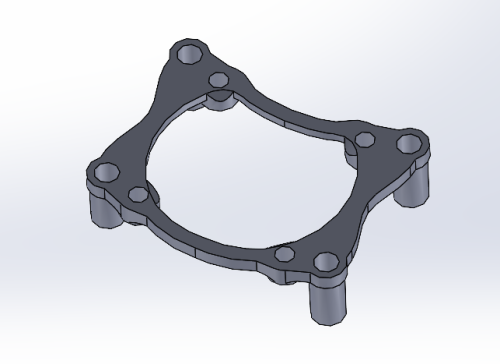
MGN 12 Y rail mod for Trident gantry
This mod allows you to use MGN 12 rails for the Y axis on your Trident Gantry. I think it will work on a 2.4 as well. All geometry is left stock except for the linear bearing mount. Enjoy
1,513 downloads
-
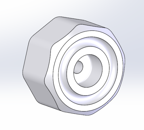
Voron foot with Oring
I didn't like any of the Voron feet I could find, so I made this one. No additional hardware required over stock, aside from a 4x20 oring to snap into the groove on the bottom. Adds just enough cushion, and anti-slip properties to the printer for my liking.
76 downloads
(0 reviews)0 comments
Submitted
-
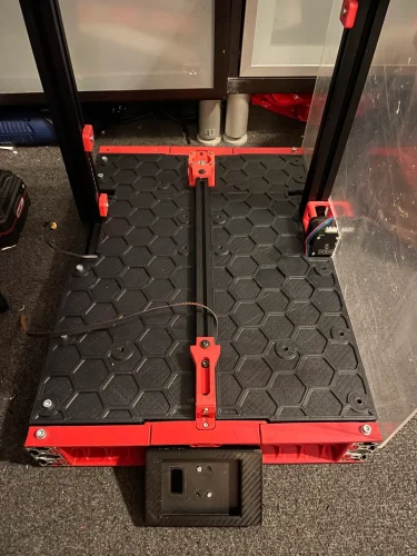
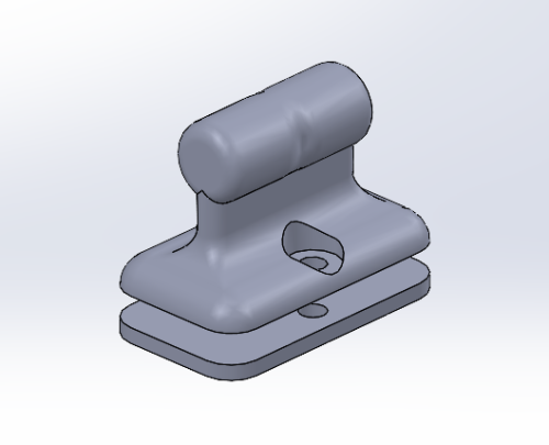
Deck Panel Lifting Handle - Trident with Inverted Electronics
It was a bit finicky to lift out the deck panel from my Trident with inverted electronics (awesome mod by the way). So I made this little handle up. It doesn't interfere with the bed at all. I used 3mm screws with locknuts so I don't get a rogue nut floating around with the electronics.
256 downloads
(0 reviews)0 comments
Submitted
-
CB1 Heatsink - 40mm Fan Mount
40mm fan mount for the BTT CB1 Heatsink. I suppose it would work without the heatsink as well, when slicing, just sink the part through the build plate far enough so that the standoffs are on the same plane. Uses Voron standard heatserts for mounting the fan. Uses stock heatsink screws to mount the part.
147 downloads
(0 reviews)0 comments
Updated
-
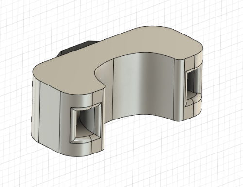
Cable Anchor - 2.5mm Ziptie
Trying to finish my Trident build, and can't get 1.8mm zipties for a reasonable price. I have a bunch of 2.5mm on hand, so I modified the original cable anchor to accept the larger zipties and also increased the saddle size a bit.
105 downloads
(0 reviews)0 comments
Updated