Search the Community
Showing results for tags 'chirpy'.
Found 3 results
-

Version 2022.08.16
399 downloads
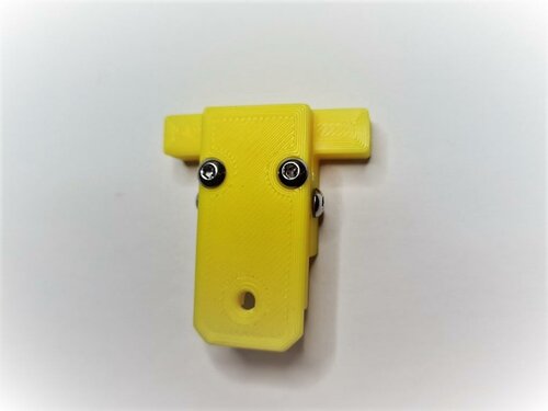
Runout UnKlicky Sensor The Runout UnKlicky Sensor is a filament runout sensor that can be used to pause a print if printing filament breaks, runs out or otherwise is no longer present in the sensor. The design uses magnets as the switch, making it easy and cheap to source BOM components. Printing: Components: 1x Pin.stl 1x Roller.stl 1x Base.stl (different options are available[*]) 1x Top.stl (different options are available[*]) Printer: Use the Voron defaults and print in ABS or better The parts are orientated correctly in the STLs [*]Base and Top: There are 3 bases and 4 tops to choose from: Bases: Base.stl is the standard base with push in holes for the PTFE tubes Base_PC4-M6.stl which allows the use of PC4-M6 connectors for the PTFE tubes Base_Collet.stl which allows the use of E3D M4 collets Tops: Top.stl is the standard top with no mounting options Top_2020.stl provides mounting to 2020 extrusions using a t-nut Top_1515.stl provides mounting to 1515 extrusions using an inserted nut Top_1515_NoNut** provides mounting to 1515 extrusions if you have no inserted nuts available [**] The Top_1515_NoNut can be used if you don't have any free nuts. It snaps into the extrusion. If it moves or slips, you can use a M2x10mm self-tapping screw to secure the sensor to the extrusion. Do note that the screw can scratch the inside the extrusion if that might bother you. BOM: 5x M3x8mm SHCS/BHCS (2x for the wired screws, 2x for the top/base, 1x for 2020 extrusion mount) 2x 6x3mm neodymium magnets (for the switch) 1x M2x10mm (optional for 1515 extrusion mount) 1x M3 Hammer T-Nut (for 2020 extrusion mount) 2x fork connectors (optional - for attaching wires) Assembly: Parts used: Insert one of the magnets into the pin, push it in fully so that it shows in the groove gap: Insert the corresponding pin into the base and make sure that they attract from the outside as shown: Insert the pin into the base with the pin grooves to the sides for the screws to enter. The pin should be pushed down to the bottom by the magnet in the base. Push the pin right up to the base magnet and screw in the screws to either side of the pin: Place the top on the base and secure with two screws: Attach cables to each screw that goes into the pin. There is no polarity and no voltage so it doesn't matter how they are connected. I used fork connectors for ease of use. Make sure the pin screws are screwed in tightly: Hook up the wires to a multimeter and put it on it's continuity test. It should show resistance (and/or beep) when there's no filament in the sensor: It should show no resistance (and/or remain silent) if you fully insert some filament into the sensor. Feed the filament through a few times from each side to ensure that you do not see any resistance when filament is present, and that you do see resistance when there is none: Wiring: Wire to an end-stop or similar pin. Do not connect to voltage, only to pin and GND. For example, with the BTT SKR MINI V2.0 you could use the E-STOP pin (PC15) and GND. For the BTT SKR Pico you could also use the E-STOP pin (gpio16) and GND. Klipper: A simple configuration is available in this repo. Upload and include runoutunklicky.cfg in your printer.cfg and change the PIN definition to the one you chose on your MCU. The config file contains what is required to use a runout sensor, but it will only literally pause the machine and resume when prompted. To have the toolhead parked away from the print to an accessible place to change filament, implement one of the following examples in your klipper configuration: AndrewEllis93 Mainsail Test by inserting and removing filament. If it shows incorrectly in klipper add a ! in front of the PIN definition and test again. Credits: Thanks to: chestwood96 for inspiration from the UnKlicky probe for SlideSwipe majarspeed for the Unklicky probe jlsa1 for the Klicky and Unklicky probes al3ph for the -
Version 2022.08.16
414 downloads
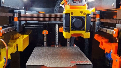
Nozzle Wiper This is a nozzle purge and wipe mod for the Voron V0.1. It is based on the SlideSwipe magnetic probe by chestwood96. It uses a snap in frame clip, that doesn't require screws, to attach a servo that extends a bucket and brush over the build plate for the hotend nozzle to clean it of filament debris for cleaner prints. Goals: Servo used to extend system over the print bed Bucket and brush to clean nozzle Snap in frame clip that does not need screws Klipper macros to control the entire process These have all been implemented in this public release. Printing: Use the Voron defaults and print in ABS or better The parts are orientated correctly in the STLs There is a single All In One STL that fits onto the v0.1 build plate to make life easier BOM: 1x Micro Servo 9G Servo Motor (SG90/MG90) 2x M3x8mm BHCS (for servo mount) 2x M3x6mm BHCS (for brush holder mount) 2x M2x10mm self tapping screws (optional: for snap in frame clip) 1x Nozzle cleaning brush in Copper 3x OD 4mm, length 16mm, PTFE tube 1x OD 4mm, length 7mm, PTFE tube Hardware: Brush: https://www.amazon.co.uk/gp/product/B08H8SXBKM https://www.aliexpress.com/item/4000801101276.html Servo: https://www.amazon.co.uk/gp/product/B0972M7JN1 https://www.aliexpress.com/item/1005001956791642.html Assembly: Step 1 - Set Servo Take the servo and attach a single arm to the top. Slowly and gently rotate the rotor clockwise until it hits its limit. Remove the arm and replace it on the servo so that it is positioned slightly more than 90 degrees clockwise as shown in the picture above. This sets the servo arm to its 0 position. Use the smallest screw in the servo packaging to affix the arm to the servo in that position. Step 2 - Parts Preparation Remove the support tabs from the bucket. Cut down the brush head so that it matches the internal width of the brush holder. It's soft plastic so can be cut with a craft knife or a pair of angle cutters. Cut the PTFE tube into 3 lots of 16mm and 1 lot of 7mm. These will act as the hinges. Step 3 - Fit Servo to Mount Push the cable connector through the slot provided in the servo mount as this will run on the inside of the extrusion. Fit the servo into the mount and fix in place with 2 M3x8mm screws. You may need to fettle the plastic around the hole for the top of the servo for it to fit. Note the correct orientation of the servo. Step 4 - Servo Section Assembly Place 1 of the 16mm pieces and the 7mm piece of PTFE tubing into the sections as shown above. Place the section with the space for the servo arm first and then the double ended section behind it. Carefully seat the PTFE tubes into the servo mount and fix in place with the angled part shown to the top of the mount: Step 5 - Brush Section Assembly Place the remaining pieces of 16mm PTFE tubing into the ends of the fitted sections and then fix onto the brush holder using the remaining 2 M3x6mm screws. Fit the brush head into the brush holder: Step 6 - Motion Slowly and carefully, manually extend and straighten the arm to ensure a full range of motion: Step 7 - Wiring Before permanently mounting the nozzle wiper to the printer test whether it works as expected by wiring the servo to the MCU from outside of the printer. Red wire = 5v Brown wire = GND Orange wire = signal pin There are various choices for connecting the servo to the MCU. Here will will refer to the BTT SKR Mini E3 V2.0. Always turn off the printer before connecting or removing anything to or from the MCU. The simplest is to connect to the Neopixel or E0-STOP connector if it is not in use as it provides all 3 required connections. Alternatively, a Klipper Expander can be used if there are no free pins. Remember, do not fit the arm to the printer at this point. Step 8 - Klipper Upload the nozzlewiper.cfg file to your klipper configuration directory on the raspberry pi. If using Mainsail you can do this in MACHINE -
Version 2022.07.20
199 downloads
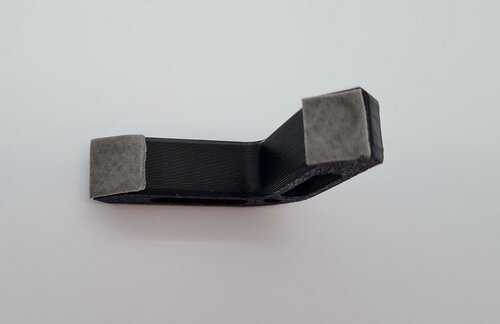
TipTophat TipTophat is an alternative Tophat for the Voron v0.1 which uses the BOM panels. It provides 30mm in additional height as well as better access via the additional door. It places the side panels fully virtically to make the tophat square. It also comes with hinges that can be used with the Tophat hinge mod. For the bleeding edge releases, see my development repo Printing: Use the Voron defaults and print in ABS. I have successfully printed the main body part(s) using 0.5mm layer width and 0.25mm layer height with 25% infill. This reduces both the time to print and the amount of filament used The parts are orientated correctly in the STLs If using the rear hing, print the appropriate Hinge_panel_left and Hinge_panel_right from Tophat hinge mod There is the choice of printing the whole body using the Unibody if you have a printer with a print bed of at least 238x238mm. Otherwise, you can print the separate quarters on a printer with at least 119x119mm printer bed. So they can be printed on a Voron v0, but it will be tight! BOM: Original BOM panels (panels of 2.5mm and 3.0mm have been tested) 28x M3x8mm** SHCS/BHCS (2x door frame hinge, 4x rear hinge (optional), 18x panel connectors, 4x tophat pins (optional)) 1x M3x12mm SHCS/BHCS (door hinge) 1x M3x25mm SHCS/BHCS (door hinge) 28x Brass heat inserts (2x door frame hinge, 4x rear hinge (optional), 18x panel connectors, 4x tophat pins (optional)) 2x 6x3mm Neodymium magnets VHB tape ** If your panels are 3mm in depth you will need to substitute 4x M3x8mm screws for 4x M3x(10 or 12)mm screws for the four mid connectors Assembly: Note: These instructions use directions based on the tophat in front of you being upside down with the back facing away from you and the front in front of you. Once you place the tophat on the printer, instruction directions are as you look at the printer from the front. Building the frame and inserting the panels: Place brass heat inserts into all the holes you are going to use. This is likely to be everything apart from the top 4 holes. Those top 4 holes are if you use the stock style pins to locate the tophat on the printer instead of using hinges at the back. If you are building using the unibody instead of the four quadrants, you need to arrange the four quadrants with Q1 at the back left, Q2 back right, Q3 front left, Q4 front right. They need to be aligned correctly. Place the top panel into the center of the bed and attach four connectors being very careful not to overtighten them, otherwise you can easily crack the print or the panels. It's better to have the connectors loose initially and tighten slightly until the panel doesn't move. Now work from the left, to the back, to the right, using the side and bottom connectors for each panel. Building the door: The door connector takes a single 6x3mm Neodymium magnet. You should be able to press fit the magnet into the hole. If it's too loose, use a bit of superglue. If it's too tight, use a file of drill bit to widen it a little. Attach this to the frame. Take the two door hinge parts and assemble. The screws go into plastic, so do not tighten. The hinges should be a little bit loose so that it moves cleanly without binding. This can be adjusted later. Put VHB tape on the panel hinge. With the hinge open, put the panel into place abutting the panel into the hinge and centered. Press the panel to the hinge with some pressure to ensure a good seal. Screw the hinge to the side of the tophat frame. There is adjustment available here for later if there are issues with the door opening/closing or being askew. If you are going to use the hinged tophat, screw the hinge parts to the back of the tophat frame. You should also fit the hinge parts to the printer. If you are using the standard locator pins, screw those in. Put the tophat onto the printer and screw the rear hinges together if you are using them. Note: The hinge holes are deliberately oversized to allow for different tolerances and spacing for the tophat to sit well on the printer. Hanging the door: Open the tophat door and close the main printer door. Now close the tophat door and check that it does not hit the main door. If it does there are a few adjustments that can be made later: Adding the handle: Take the door handle and the second magnet. With the tophat door closed, put the magnet against the frame magnet to get the correct orientation (use a marker pen on the magnet if it helps). Maintaining the correct orientation place the magnet into one of the holes in the foot of the handle: Place VHB tape over both of the handles feet: With the tophat door closed, align the handle with the magnet at the top opposite the magnet in the frame and keeping the handle straight press it onto the door. If it's not quite right, it should be fairly easy to carefully, and slowly, remove the handle and do it again. You can adjust the frame mount from the inside screws to change the fitting of the hinge. You can also tighten and loosen the hinge screws to lower and raise the door panel. If none of that works, unscrew the door hinge and take the hinge tophat door off. You can usually remove the hinge from the door, by very slowly pulling the hinge from the door panel, being careful not to snap the hinge or crack the panel. You can then redo the hanging steps for a better fit. Changelog: 2022-07-22 Updated Body Quarters and STEP file