


-
 8
8
About This File
This is an intermediate/advanced configuration, it's recommended to first build your Voron to the stock configuration
That way, you will be better familiarized with the concepts that are presented here and will have a much more enjoyable experience.
With an integrated mount, the bed can be fully used during printing, the bed only cannot be probed (at most) 6mm on the left side, this is due to the design of the probe, that extends below the nozzle.
There are currently two other probes available to use on the V0.1, Slideswipe and Sideswipe.

Above all, have fun and be excellent to one another, the instructions on how to install and setup the klicky probe for Vorondesign V0(.1) can be found [here](https://github.com/jlas1/Klicky-Probe/tree/main/Printers/Voron/v0), or below on this download
For me, and for a lot of users, it is working very well, if you decide to use it, give me feedback, either here, or on discord, my discord user is JosAr#0517.
By standing on the shoulders of giants, let's see if we can see further.
Mounting options
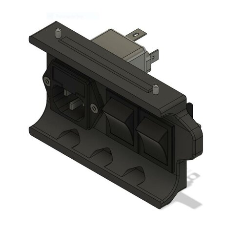
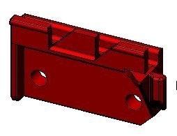
Probe dock mount
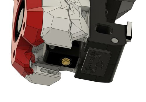
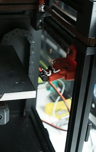
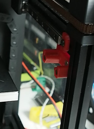
The probe dock is mounted to the front right extrusion, where it minimizes the chance of being removed inadvertently during printing, like this:

There are several mounting options, depending on your setup:
It can be frustrating on the v0 to add extra m3 nuts on the 1515 extrusion after the assembly is complete, so there are several screwless probe dock options to avoid that scenario.
| Screwless variable | Fixed | Fixed extrabeef | Top screws | Side screws |
|---|---|---|---|---|

|

|
|
|
|
| recommended for most setups, does not require extra m3 nuts on the extrusion (v0.0/1) | fixed position, does not require extra m3 nuts on the extrusion (v0.1) | fixed, fits X carriages that are 2mm thicker, does not require extra m3 nuts on the extrusion(v0.1) | fixed, requires 2 extra m3 nuts on the top extrusion (v0.1) | fixed, requires 2 extra m3 nuts on the front extrusion (v0.1) |
There are also some more mounting options on Usermods, like a servo powered dock. Check it out
Probe toolhead mount
The v0 toolhead was not designed to use a probe, so there is no inbuilt location to add one, so i designed two options for the v0.1 variant and one for the original v0.
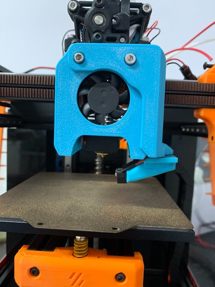
Front cowling mount (v0.1)
You can install a mount the attaches to the front of the toolhead cowling, it will need 2/3mm of X space on the front right of the bed to avoid picking the probe up by accident, it is very easy to install, it's ideal to test the concept of probing on the v0.1
You will require 2x M3 x 40mm (BHSC preferably) that are not on the V0(.1) BOM, there is an included wire path with zip tie support, to keep your printer looking good.
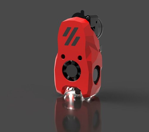
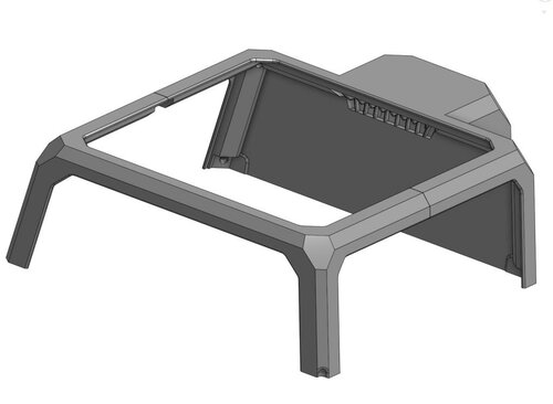
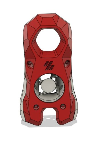
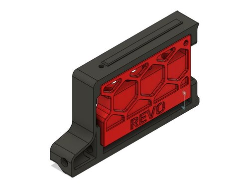
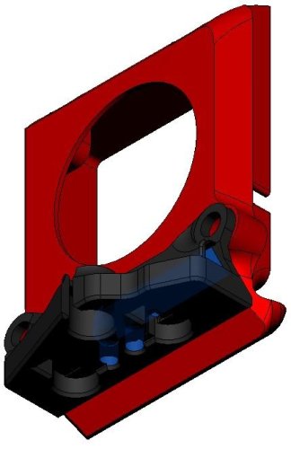
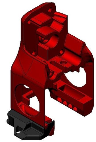
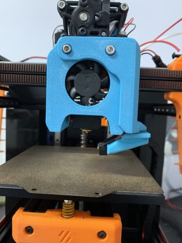
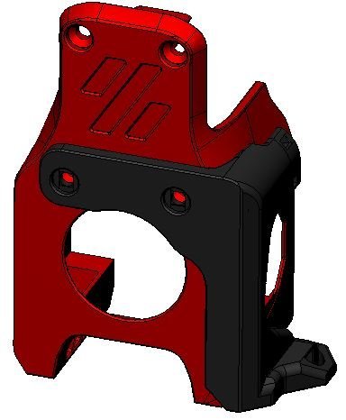
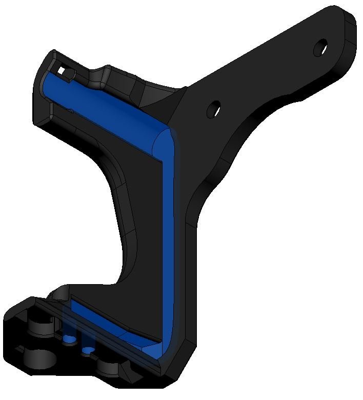
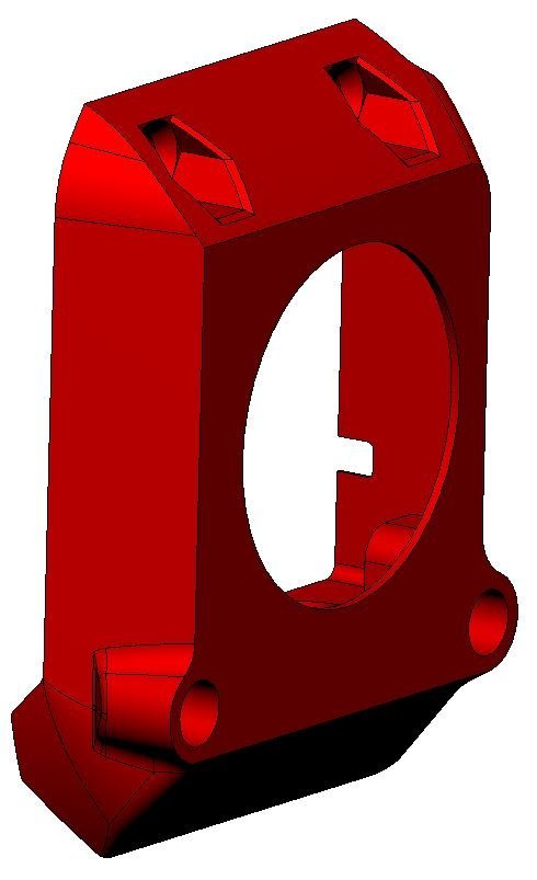
Integrated cowling (v0.1)
You can replace the cowling with a version that has a cutout to allow the klicky mount to attach, it has no impact on the cooling performance of the probe, it also includes a wire path to the back of the miniAB.
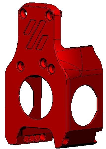

This method allow mounting of different probes on the V0.1, currently only klicky uses this mount, hopefully that can change in the future.
It also allows to pick up the probe at X121, effectively outside the bed, incurring in a no print space lost.
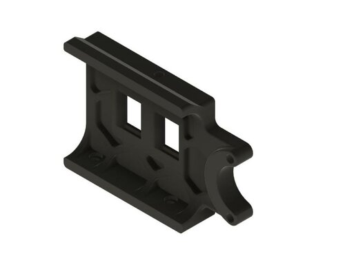
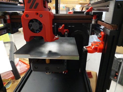
Fan duct mount (v0.0)
On the V0.0, you do not need to reprint the entire cowlink, you only need to replace the right fan duct with a version that has a mount for klicky, it has no impact on the cooling performance of the probe, it also includes a wire path to the back of the miniAB.
|

|
|---|
This version has seen little tests because of the lack of a sufficient number of v0.0 to test on.
If you end up using this version, please tell me at what X do you dock and attach the probe.
It is also necessary to use the Screwless variable dock mount
Bill of Materials (BOM)
Tools:
- 1.5mm Drill (optional)
- Multimeter to check for Continuity
- Super Glue (optional)
- Soldering Iron
Probe:
- 1x microswitch (the omron D2F-5 or D2F-5L (removing the lever is required), other also work with reduced accuracy or repeatability (mostly anecdotal evidence, needs a proper sudy)
- 2x M2x10 mm self tapping
- 10cm of 22AWG cable (to wire the magnets to the switch)
- 5x 6 mm x 3 mm magnets (N35 magnets work)
Probe mount:
| Front cowling mount (v0.1) | Integrated cowling mount (v0.1) | Fan duct mount (v0.0) |
|---|---|---|
| 4x 6 mm x 3 mm magnets (N35 magnets work) | 4x 6 mm x 3 mm magnets (N35 magnets work) | 4x 6 mm x 3 mm magnets (N35 magnets work) |
| 2x 20cm 22AWG cable (to connect the Klicky Probe to the umbilical termination point) | 2x 20cm 22AWG cable (to connect the Klicky Probe to the umbilical termination point) | 2x 20cm 22AWG cable (to connect the Klicky Probe to the umbilical termination point) |
| two wires to connect the controller to the extruder motor vicinity | two wires to connect the controller to the extruder motor vicinity | two wires to connect the controller to the extruder motor vicinity |
| 2x M3 x 40mm BHSC | 1x M3x6 mm BHSC Screw | 1x M3x6 mm BHSC Screw |
| 1x M3 threaded insert M3x5 mmx4 mm | 2x M3 threaded insert M3x5 mmx4 mm |
Probe dock:
- 1x 6 mm x 3 mm magnets (N35 magnets work)
- 2x M3x16 mm
Probe dock mounts:
| Screwless variable (v0.0/1) | Fixed (v0.1) | Fixed extrabeef (v0.1) | Top screws (v0.1) | Side screws (v0.1) |
|---|---|---|---|---|
| 2x m3 nut | 2x M3 threaded insert M3x5 mmx4 mm | 2x M3 threaded insert M3x5 mmx4 mm | 2x M3 threaded insert M3x5 mmx4 mm | 2x M3 threaded insert M3x5 mmx4 mm |
| 2x m3x8 mm | 2x m3x8 mm |
Sourcing
To get the best experience, please consider purchasing from the trusted list of suppliers bellow.
Parts location
The probe STL's are located here.
The printer specific STL's are located here.
The CAD with all the parts are here.
What to print
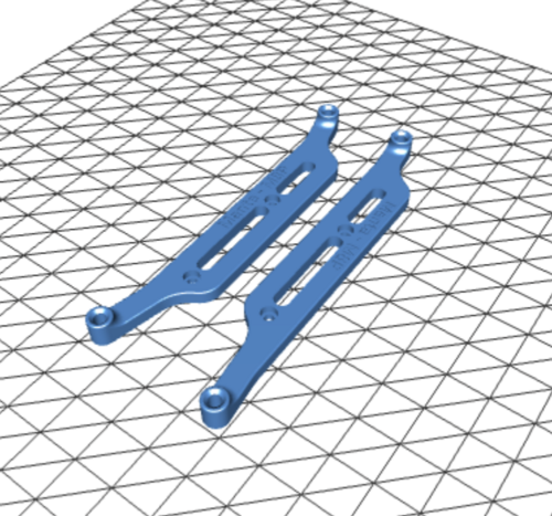
Probe
- 2x KlickyProbe_Long_v2.stl (keeping a spare is always a good idea)
The KlickyProbe_v2.stl is also compatible, but has a different Y offset and cannot probe all the bed.
Helpers to pressfit the probe magnet
-
Probe_magnet_pressfit_helper.stl
-
Probe_magnet_holder.stl
-
Longer_probe_pressfit_helper.stl
Probe mount
| Front cowling mount (v0.1) | Integrated cowling mount (v0.1) | Fan duct mount (v0.0) |
|---|---|---|
| Front_cowling_mount.stl | MiniAB_Dragon_Cowling_wKlicky.stl | V0_Fan_duct_wKlicky.stl |
| v0.1_integrated_mount.stl | v0.1_integrated_mount.stl | v0_integrated_mount.stl |
There are also other integrated cowlings, check the [STL] folder, namely, the Serpa_Mini_Dragon_Cowling_wKlicky.stl from Kyrios and the LGX Lite cowling from Bondtech.
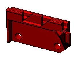
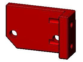
Probe dock
- Probe_Dock_v2.stl
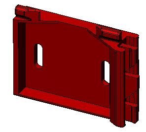
Probe dock mounts
| Screwless variable (v0.0/1) | Fixed (v0.1) | Fixed extrabeef (v0.1) | Top screws (v0.1) | Side screws (v0.1) |
|---|---|---|---|---|
| DockMount_variable.stl | DockMount_fixed.stl | DockMount_extrabeef.stl | DockMount_TopScrews.stl | DockMount_SideScrews.stl |
Printing instructions
Recommended printing settings:
- initial layer height:0,24
- layer height: 0.2mm
- bottom/top/perimeters: 4
- infill: more than 23%
- infill type: Cubic
- Thin walls: On
It was tested and printed with ABS, might work on other materials, if you try, let me know how it worked out.
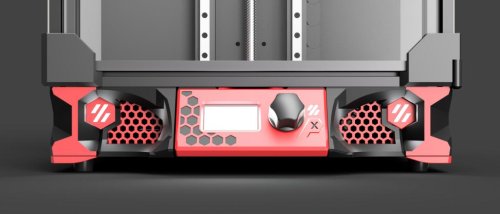
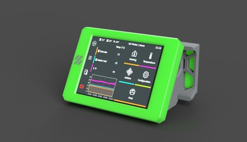
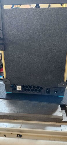
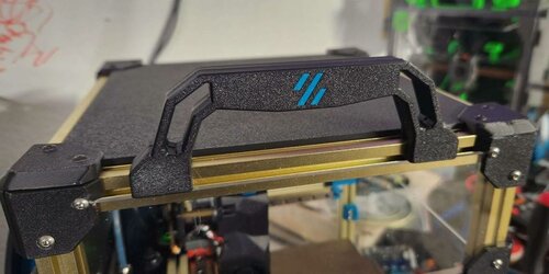
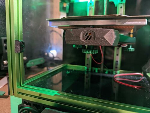
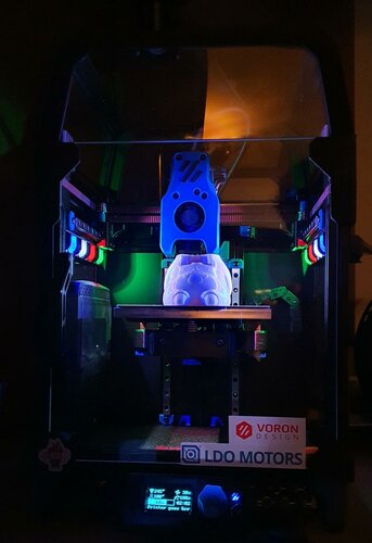
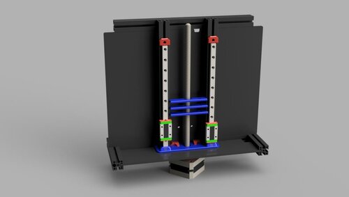
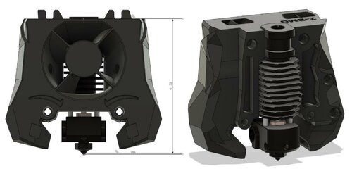
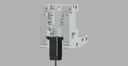
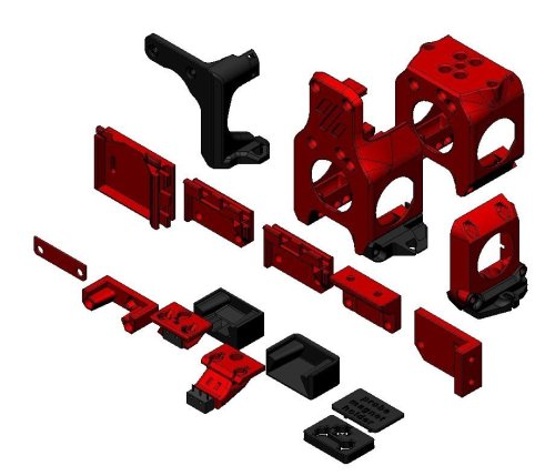
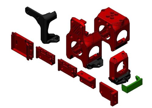
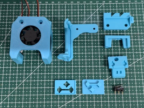
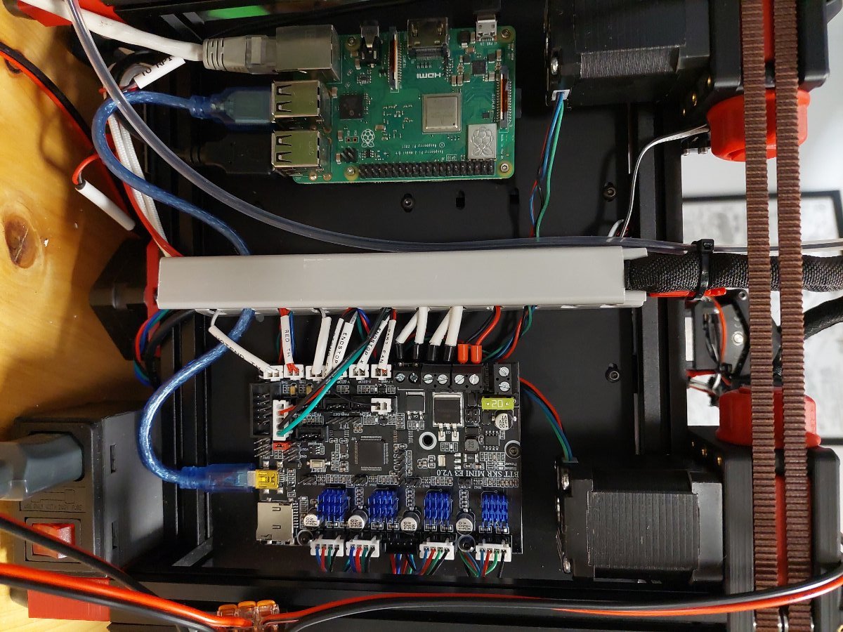
Typical V0.1 components
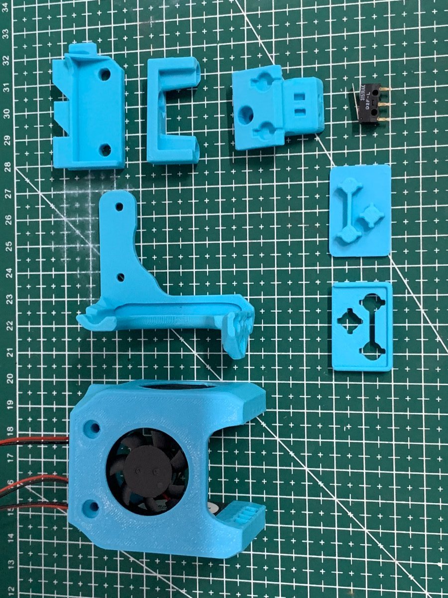
(the images with the green background were provided by user SunB#1489 and are being used with permission).
Assembly
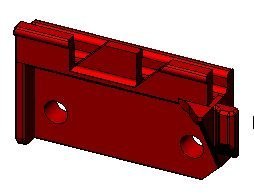
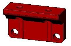
Step 1 - Dock mount and Probe Dock assembly
In this examples, the Fixed dock will be used.
- 2x M3 threaded insert M3x5 mmx 4 mm
- 1x 6 mm x 3 mm magnets
- 2x M3x16 mm
- Super Glue
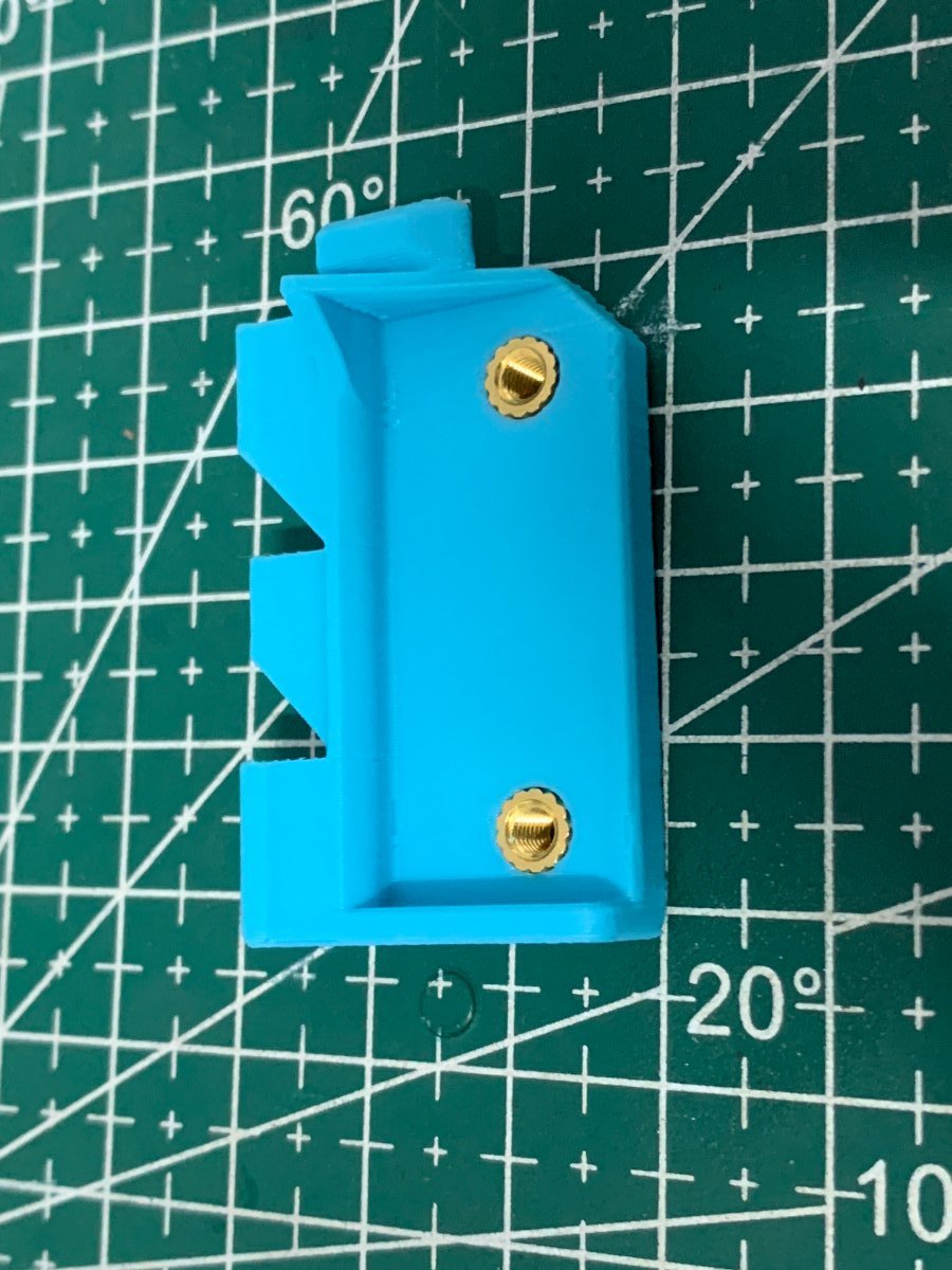
Here we will use the Fixed dock as an example, the other docks are very similar.
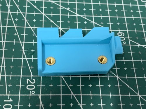
Install your heat set threaded inserts like you did within your Voron build.
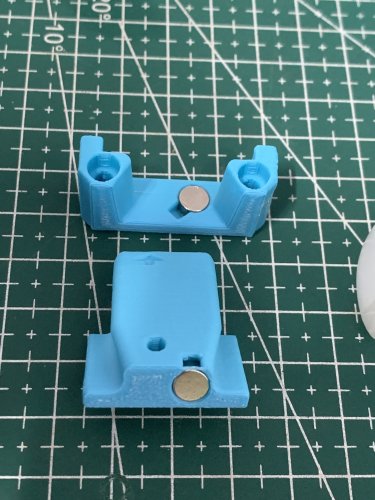
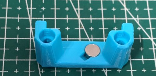
Install the magnet in the Probe dock, make sure that the magnet is fully inserted, it's top should be below the plastic.
Screw the dock onto the Dock mount with the two M3x16mm screws.
Secure the magnet with a dab of super glue (not a lot, just a drop).

Mount the Probe Dock to the front right extrusion, snap first on the front extrusion, then on the top one (do this after assembling the probe).
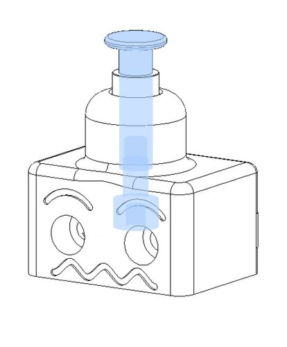
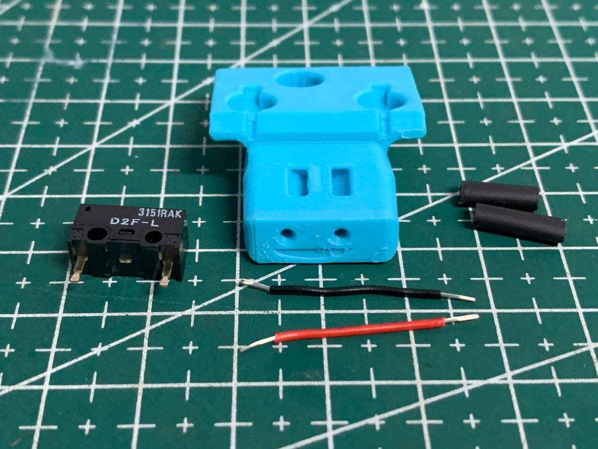
Step 2: Probe Assembly
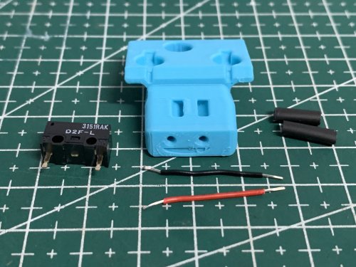
For the probe assembly you need the following parts:
- 1x microswitch
- 2x M2x10 mm self tapping
- 5x 6 mm x 3 mm magnets
- 10cm of 22AWG cable
- 1.5mm Drill (optional)
- Multimeter to check for Continuity
- Super Glue
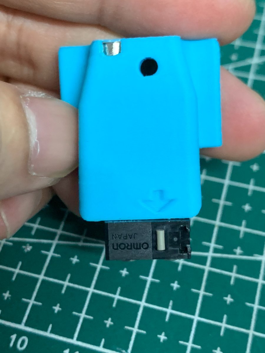
Maybe you need to clear the holes for the microswitch, a 1.5mm drill bit should work fine.
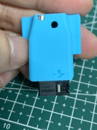
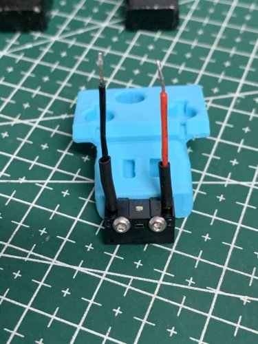
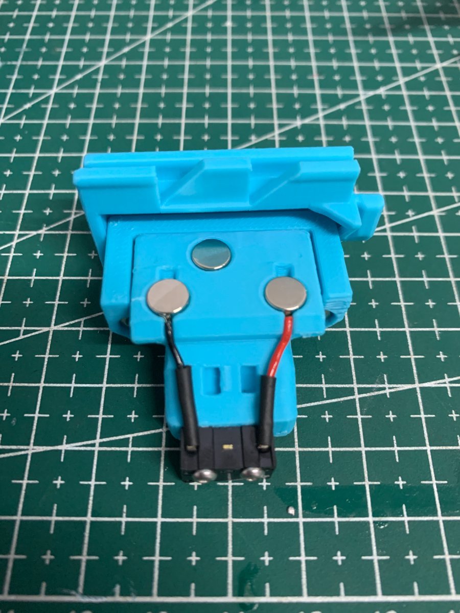
Install the microswitch so that the arrow on the probe body is pointing to the little switch.
The best way to install the back magnet is to attach a magnet to the probe dock and slide the probe on the dock to insert some distance and the insert he remaining with a tool, it should be slightly below the plastic.
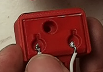
Then take your self tapping screws and screw the microswitch in place, you should also now solder the wires to the outside pins of the switch, that way making this a Normally Connected probe.
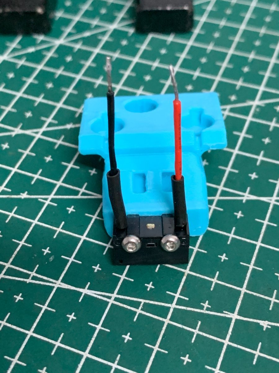
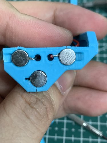
You should place the wires cover outside the ducts to the magnets and install them in the space below the magnets, more like the right wire is on the image below.

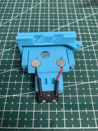
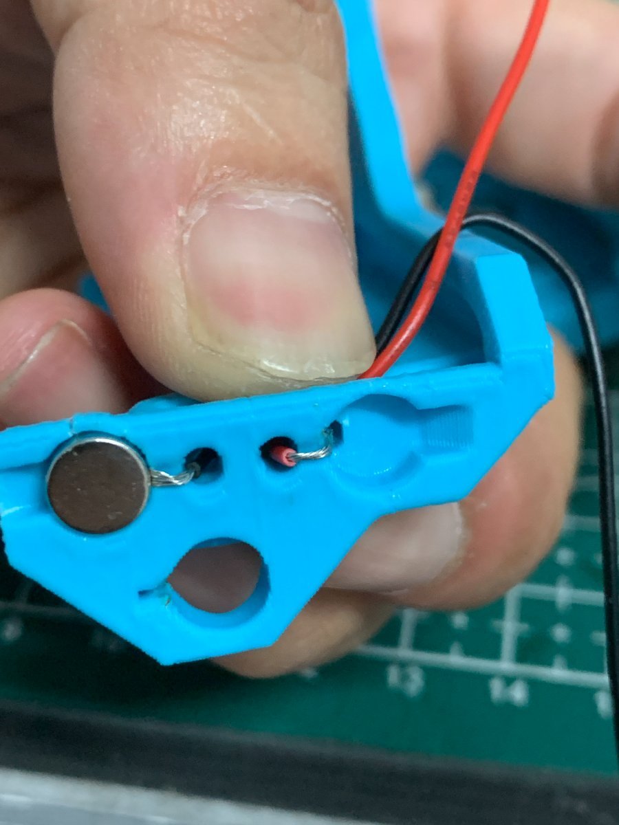
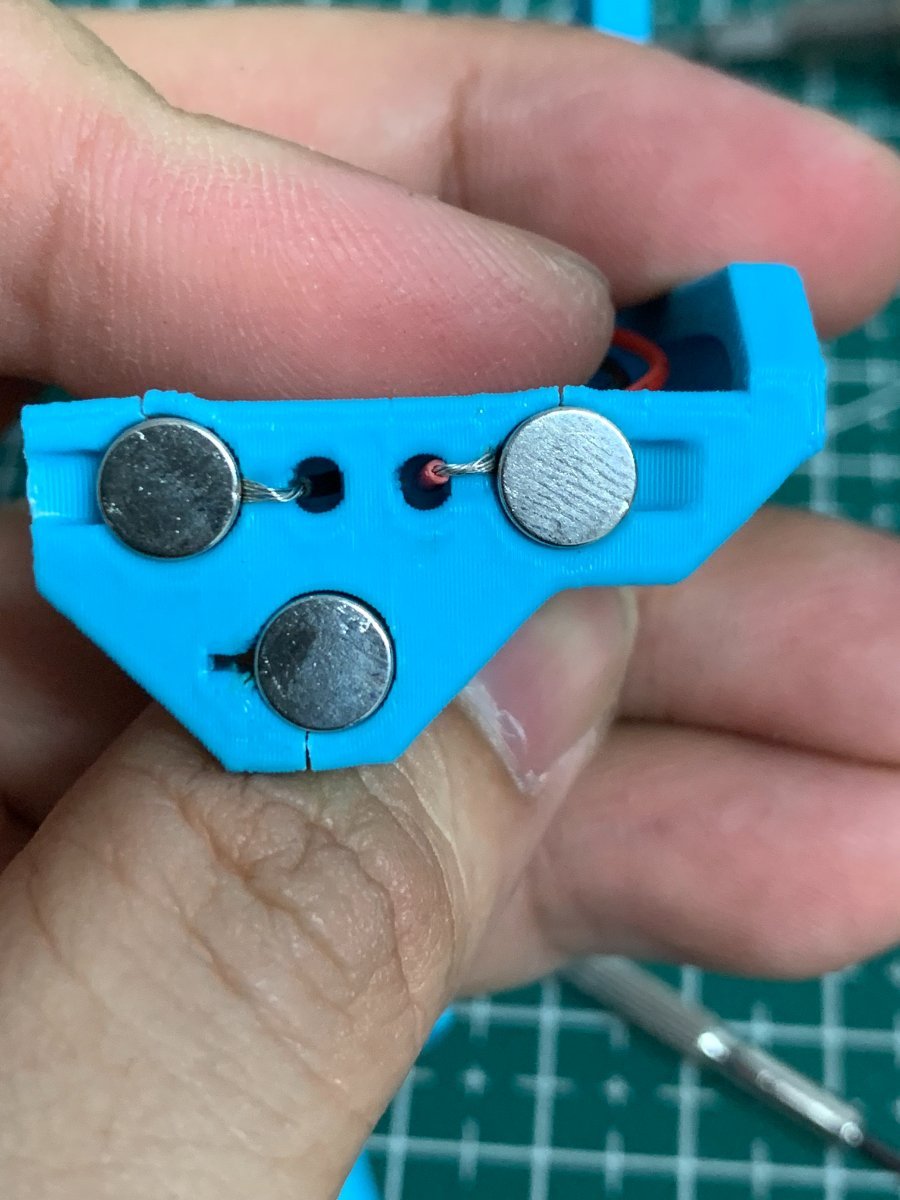
You want to install the magnets in the way that the ones which are connected to the microswitch, have the same polarity.
Before placing the switch magnets, use some super glue on the holes (not a lot, just a drop), avoid the wires and the top of the magnets.
The 3rd magnets (there are two) should have the inverse polarity, wait until the system is complete and assembled before gluing the magnets, they might need adjustment to ensure a good fit on the mount.
You can use the included pressfit helpers to help in securing the probe when you are inserting the magnets.
There is no need for soldering, the probe microswitch connectors are press-fit on the magnets, they should remain with the top above the probe plastic.
As the last step of the probe assembly check if you have continuity between two magnets that connect to the switch.
If you have a normally closed switch (as you should), then you should have a current flow, so continuity is established. When you press the switch you should lose continuity. When you have a normally open switch then the behavior is the other way around.
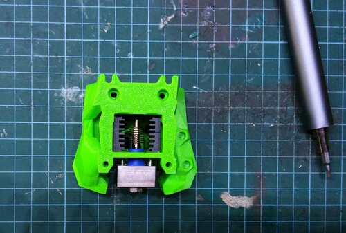
Step 3: Probe mount Assembly
In this example, the Front cowling mount will be used.
For the Front cowling mount assembly you need the following parts
- 4x 6 mm x 3 mm magnets
- 2 x 20cm 22AWG cable to connect the Klicky Probe to the Mircofit Terminal
- two wires to connect the controller to the extruder motor vicinity
- some microfit or JST hardware
- 2x M3 x 40mm BHSC
- Multimeter to check for Continuity
- Super Glue
The probe mount wires are also connected with pressure from the magnets, you can use the probe magnets as a template to insert the probe mount magnets, it is easier that way, so that the magnets are not inserted the wrong way.
again, before placing the wire magnets, use some super glue on the holes (not a lot, just a drop), avoid the wires and the top of the magnets.
The 3rd magnets (there are two) should have the inverse polarity, exacly like on the probe.
Wait until the system is complete and assembled before gluing the 3rd magnets, they might need adjustment to ensure a good fit on the probe.
|
|
|
|---|
(The mount has since been improved a bit to avoid cracking)
After everything is assembled let's check again for continuity, this time joining the ends of the cable and testing connectivity on the two wire magnets that have a cable.
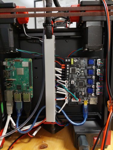
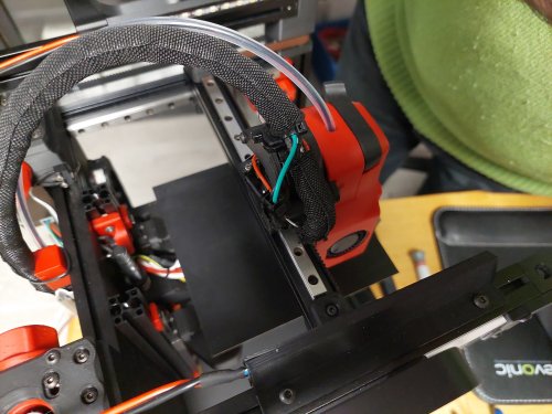
Step 4: Probe Mount installation and wiring
For the installation you need the following parts:
- 2x M3x40 mm BHSC Screws
Route the probe mount cables to near the end of the V0 umbilical, install a male terminal in there.
Before going further, please turn off the printer, the SKR boards are very picky with short circuits.
Connect a female terminal to the wires that will run in the umbilical from the toolhead to the controller.

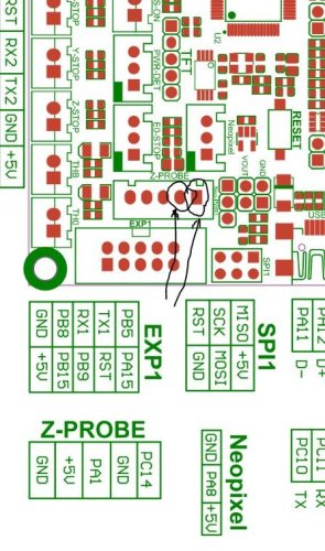
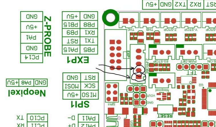
Connect the wires from the Klicky Probe to the Zprobe port, on GND and PC14 bin (I reused the LDO kit connector)
|
|
|---|
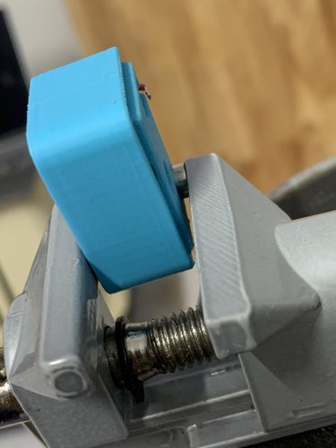
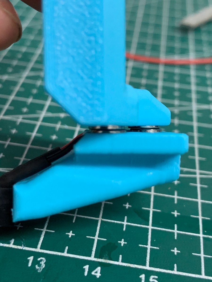
When testing the docking and attachment of the probe, make sure that the back magnet of the probe and the dock magnet do not touch, if they do, it will make attaching the probe much harder.
Step 5: klipper configuration
Unfortunately, I do not know how to document RRF probe configuration, so here is only Klipper configurations.
As of right now, klipper and RRF have no inbuilt support for a removable probe, fortunately, it does support very robust macro programming, so you will need to add macros to be able to dock and attach the probe as necessary, as well as supporting the rest of the functions that require the usage of a probe.
The macros and instructions on how to configure are located on the Macro directory, you need to check that before continuing on the build, there are also some RRF scripts that work for the Voron V2.4.
For the Voron v0, these are the recommended configuration on the klicky-variables.cfg:
variable_verbose:               True  # Enable verbose output
variable_travel_speed:          100   # how fast all other travel moves will be performed when running these macros
variable_dock_speed:            50    # how fast should the toolhead move when docking the probe for the final movement
variable_release_speed:         55    # how fast should the toolhead move to release the hold of the magnets after docking
variable_z_drop_speed:          20    # how fast the z will lower when moving to the z location to clear the probe

variable_safe_z:         	    25    # Minimum Z for attach/dock and homing functions
# if true it will move the bed away from the nozzle when Z is not homed
variable_enable_z_hop:        True    # True v0

#Dock move
Variable_dockmove_x:             0    # Final toolhead movement to release
Variable_dockmove_y:            40    # the probe on the dock
Variable_dockmove_z:             0    # (can be negative)

#Attach move
Variable_attachmove_x:          30    # Final toolhead movement to Dock
Variable_attachmove_y:           0    # the probe on the dock
Variable_attachmove_z:           0    # (can be negative)

variable_max_bed_x:             120   # maximum Bed size avoids doing a probe_accuracy outside the bed
variable_max_bed_y:             120   # maximum Bed size avoids doing a probe_accuracy outside the bed
The sections below should be added to klicky-specific.cfg, that way, it will be loaded on klipper via a klicky-probe.cfg include.
If you would like to use a bed mesh, this is the recommended settings:
[bed_mesh]
mesh_min: 15,15
mesh_max: 105,105
speed: 100
horizontal_move_z: 20

probe_count: 3,3					#if you would like more detail, use 5,5 here
relative_reference_index: 4			 #if you use 5,5 above, place 12 here
move_check_distance: 3

algorithm: lagrange
fade_start: 1
fade_end: 10
fade_target: 0
split_delta_z: 0.0125
mesh_pps: 2,2
Regarding the Screws Tilt Adjust (Klipper probes the three screws positions and recommends the number of turns to level the bed), you can use this configuration as a reference, the probe should be over the screws when you do send the nozzle to the respective coordinate:
[screws_tilt_adjust]
screw1: 100,115          #For Long probe
screw1_name: back right
screw2: 0,115            #For Long probe
screw2_name: back left
screw3: 60,5             #For Long probe
screw3_name: front screw
horizontal_move_z: 20
speed: 100
screw_thread: CW-M3
You should test this and adjust accordingly.
This is probe configuration is with the default Voron v0.1 SKR mini E3 v2 configuration, with the probe connected to the PC14 pin, please update it to your specific configuration:
[probe]
#with Long Klicky Probe
pin: ^PC14
x_offset: 8 #(9.5 with front cowling)
y_offset: 0
z_offset: 14.5
speed: 7
lift_speed: 7

samples: 3
samples_result: median
sample_retract_dist: 2

samples_tolerance: 0.01
samples_tolerance_retries: 10
I recommend a probing speed between 5mm/s and 10mm/s, you may experiment to see what is the better speed for your machine. Please confirm that if you are not using a endstop pin, that the pull-up is enable by using the ^ sign, normally the endstop pins have a hardware solution that does not require this configuration. Depending on your switch you may need to add a ! to invert that pin (normally open vs. normally closed).
Z endstop and Probe configuration
If you want to use the Klicky Probe as your Z endstop, you need to change the endstop_pin: under the [stepper_z] section to probe:z_virtual_endstop.
Just comment out the old one and add a new line endstop_pin: probe:z_virtual_endstop.
You will need to update the Z probing variables, set the two variables below to 0, it will probe the middle of the bed.
variable_z_endstop_x:     0
variable_z_endstop_y:     0
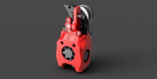
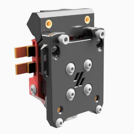
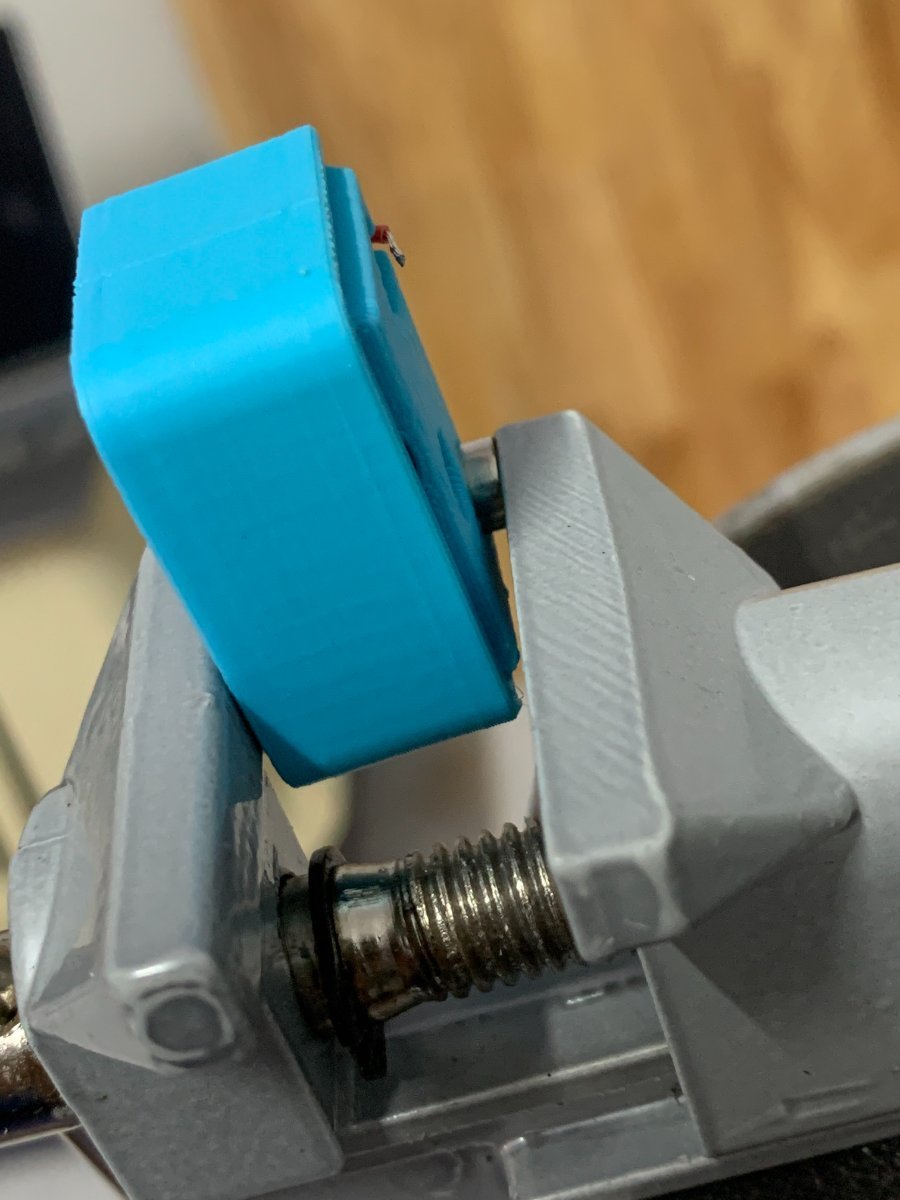
Assembled Klicky Probe

Step 6: klipper Dock/Undock configuration
X max position adjustment
Even in the stock X endstop with a lever, you normally can add a extra mm of X travel due to the lever extra trigger distance:
[stepper_x]
position_endstop: 120
position_max: 121
Adjust Probe Pickup Position
One of the last things we need to do is to adjust the probe pickup position.
Make sure that the x and y axis are homed and the probe is manually attached to mount.
Now manually (with gcode commands) move the toolhead to the probe dock and move it so far to the back that the probe docks, note the Y-Position.
Next, again manually, move the toolhead parallel to the probe dock until the probe it is perfectly aligned with the mount, note the X.Position.
Open your klicky-variables.cfg and find the #dock location section and edit the following two line
variable_docklocation_x:
variable_docklocation_y:
Test now with the ATTACH_PROBE and DOCK_PROBE if it docks and is removed correctly, some common points that can give problems are:
- the dock magnet is touching the back probe magnet, they cannot touch, push them further in
- the probe is hitting the dock arms, please move the toolhead more to the side where the probe does not hit, by 1mm at a time, until it works
- the probe is falling after being release, the dock is too far away, you can insert one or several 1mm spacer to move the dock and solve this
WARNING when you are doing PROBE_ACCURACY, make sure that the probe is above the bed, the PROBE_ACCURACY macro does not move the toolhead in X or Y.
Congratulations, your done :).
Firsts tests
Before starting to test klicky, and from past mistakes, please remove your PEI sheet (the probe works on the magnetic sheet) and if possible, change your printer maximum speed, acceleration and Z current, on klipper with TMC steppers, you can do this:
SET_TMC_CURRENT STEPPER=stepper_z CURRENT=0.2
SET_VELOCITY_LIMIT ACCEL=1000
SET_VELOCITY_LIMIT VELOCITY=50
Enjoy your Klicky Probe!
Dock and undock video
It is working very well, if you decide to use it, give me feedback, either here, or on discord, my discord user is JosAr#0517.
By standing on the shoulders of giants, lets see if we can see further.