-
TeamFDM.com is an UNOFFICIAL companion site for the DIY Voron 3D printer community. For official docs and final source of truth, visit the Official Voron Discord or the Voron Github
Printable Voron User Mods
Voron User Mods, or "UserMods", are a collection of community created and Team FDM curated modification for Voron Printers. All of these mods are available on the VoronUsers Github repo and unless otherwise specified follow the Voron communities GPL3.0 Licensing. Use any Mods at your own risk, if you make modification please share them on the VoronUsers repo.
Mod Authors: Have a Voron mod? Upload it at TeamFDM.com and let us know you're the author. We will ensure you can update and curate your files for more feedback! Please include tags for what Voron, or extruder your mod is compatible with.
660 files
-
 (0 reviews)
0 comments
Submitted
-
AB BN
AB-BN-30
This mod is my latest iteration on improving the afterburner hotend. The naming convention is not hard: AfterBurner BadNoob version 30
Disclaimer: It is your printer. If you do this and something breaks or if someone gets hurt, it is fully your responsibility. I take no responsibility.
Special thanks
I want to say Thank You to the Voron design team. I've really enjoyed learning from you. Thank you for sharing your files, criticism, advice, and support.
Additional thanks to Yellowfish, Long, Greg3D and all the fearless people that took time to help me along the way.
BOM
This is replacement to the stock afterburner, the required screws are ones you will just reuse from your existing afterburner.
The main thing you will need to purchase is a 5015 blower fan. You will then have to mutilate the fan by cutting off the mounting ears.
If this seems daunting to you, stop now.
*Optional de-earing tool ("dearing tool")
1 M3x0.5 heat set insert
1 M3x0.5x16 SHCS
For the mod itself:
4x M3x0.5 heat set inserts
The usual screws used in Afterburner 2.4
1 5015 blower fan (Sunon's 12volt MF50151VX-B00U-A99, SanAce B52, or Delta BFB0524HH 24v fan are recommended)
Note that sunon specifically states to NOT PWM this fan. I have been doing so for months and 10's of kilograms of pushed plastic without issue, but its important to state here.
for fan advice, look for a fan with a high static head (above .7 inches H2O) and a high max flow (5 CFM )
The SoundOriginal 24v fans from Amazon also appear to do well.
The following fans have been tested but are not as good in this application. they may work OK for abs, but not PLA or high speed abs:
Sunon MF50152V1 (the last digit here is "speed" and 1 is a much lower speed than the MF50151VX
Winsinn
Hondaly
Mechatronics
What does it do, and why should I do this mod?
This version of the afterburner fan and duct is a drop in replacement to the spec 2.4 and 1.8 afterburners. It replaces the 4020 blower with a far more powerful 5015 blower. Compared to the spec 2.4 afterburner, v24 improves the following:
* Better part cooling for both ABS and PLA filaments
* Fewer jams caused by heat creep
* Very resistant to melting ducts
* Better left-right balance
* Cleaner airflow for better overhangs
CHANGE Log
Added support for Zodiac BMO and BMS
Removed support for Slice.
Added step file for AB-BN-30
Added support for Phaetus BMS and Phaetus BMO hotend
Release to VoronUsers
In AB BN 28 and 29, we moved to a single piece front. This has a few advantages, but it appears there may be an issue causing hotend fan failures by stressing the 4010 fan at a weak point in its housing. The issue is fixed in AB-BN-30_fan_front.stl\
I also made some slight changes to focus the part cooling flow for the dragon toolhead only. I didn't see much difference from this, so I did not migrate these changes to Mosquito or E3DV6.
I just did AB-BN-xx!...why should I move to the current version?
If you are using AB-BN-28 or 29, I recommend you update the fan front piece.
Performance wise, ab-bn-25 is nearly identical to -30, but there are some changes.
Compared to the version (AB-BN-25):
Better wire management
Single piece front is stiffer
4010 moved slightly to make it easier to remove hotend without removing fans
Better fit (fixed the spacer to 6.6 mm)
Fixed the back of the mosquito hotend.
Changes made since -25 by part:
Fan_front- 100%redo from -25. improved printability, standardized walls at 1.2 mm or greater. visually redone to eliminate "intake duct" or "kenny" appearance. Incorporated 4010 fan into a single piece unit. lower half matched to the hotend-front profile. fixed issue in 28,29 with 4010 fan carrier.
Fan_back- 100% redo from -25. changed tabs to fit with the front.
Spring- reduced size to fit
Spacer-reduced thickness to 6.6mm
Hotend-E3Dv6-front, Hotend-Dragon-front, Hotend-Mos-front:
Reduced and adjusted stator to flow better with relocated 4010 fan, thickened walls at important points.
Hotend-E3D-Dragon-back- NO CHANGES FROM -25
Hotend-Mos-back- adjusted to line up with Mos-front better.
Print Settings:
I use the standard Voron print settings, but with 30% infill. I have gone as low as 0% on the hotend_front, these parts don't get a lot of stress. I also use Hilbert curve for top and bottom patterns. ABS is recommended, but these have been printed in ABS+ and PETG as well:
0.4 mm Nozzle
0.2 mm layer height
30% infill
no supports
4 vertical shells
5 solid layers top and bottom
What files need to be printed?
Everyone will need:
AB-BN-30_fan_front.stl
AB-BN-30_fan_back.stl
AB-BN-28_spring.stl
AB-BN-28_spacer.stl
Depending on your hotend you will need:
Phaetus BMS:
AB-BN-30_Hotend-Phaetus_BMS-front.stl
AB-BN-30_Hotend-Phaetus_BMS-back.stl
Phaetus BMO:
AB-BN-30_Hotend-Phaetus_BMO-front.stl
AB-BN-30_Hotend-Phaetus_BMO-back.stl
Zodiac BMS:
AB-BN-30_Hotend-Zodiac_BMS-front.stl
AB-BN-30_Hotend-Zodiac_BMS-back.stl
Zodiac BMO:
AB-BN-30_Hotend-Zodiac_BMO-front.stl
AB-BN-30_Hotend-Zodiac_BMO-back.stl
E3DV6:
AB-BN-28_Hotend-E3Dv6-front.stl
AB-BN-28_Hotend-E3Dv6-back.stl
Dragon (high flow and regular):
AB-BN-30_Hotend-Dragon-front.stl
AB-BN-28_Hotend-Dragon-back.stl
Mosquito (high flow and regular):
ANNOUNCEMENT I no longer support the hotends from Slice Engineering. I find their business practices to be inconsistent with my philosophy. It makes no sense for me to put time and effort into designing a toolhead so that they can get a better price for their overreaching patent claims. My designs are all open source. Slice is free to take them and adapt them their own damn selves, but I'm not lifting another finger to help them.
Assembly:
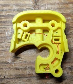
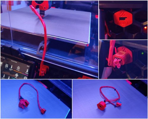
This is the fan after modification
Step 1: Cut the ears off the 5015 fan. In order to fit, you must cut the ears (mounting tabs) off the 5015 fan, and take off the top cover. The ears can be cut with diagonal clippers, hacksaw, bread knife, belt sander...whatever you have at hand. Just make it look like the image above. If you cut too much it's probably fine, as long as you don't damage the turbine.
I have included stls for an optional de-earing tool (5015-deearing-tool and 5015-deearing-tool-b). The tool is meant as a handle and guide to saw off the ears. The tool fits around the ear and its edge can be used as a saw guide to cut the mounting ear off.
Step 2: Fan test fit.
The fan fits into AB-BN-30_fan_front. We have learned that different "5015" fans have very different shapes. AB-BN is designed to allow for adjustment for your fan. Here's how:
Test fit the fan in AB-BN-30_fan_front. Looking at it from the front, move the fan around to center the turbine blades. You may need to trim your fan housing a little more. Once the fan is centered, turn this over and note where you need to add shims between AB-BN-30_fan_front and the fan. To shim this I recommend vhb tape.
Step 3: Spring THEN Fan
Once you have your shims in the right spots, remove the fan and install the printed leaf spring (AB-BN-28_spring) into fan front. The little circle tab should be cut off, it's an integral print support only. Don't forget to remove the integral print support
Insert fan into 5015 front and secure with fan spring. The spring bends back to hold the fan in place.
Step 4: Insert the 4010 fan in the AB-BN-30_fan_front. This is a tight fit by design.
Step 5: Carefully route the wires, they will exit the 5015 back.
tip: use a dab of hotglue on the fan housing to secure the wires to the fan housing
fans wiring Step 6: Insert the tabs from the AB-BN-30_fan_back into the front and take the wires out through the cutout.
mounting the fan spacer between extruder and fan assy
Step 7: Assemble with the spacer as shown and secure to the extruder body.
excess wire may be stored in the spacer
Assemble the hotend as usual.
ENJOY!
Please drop me a DM if you find this mod useful or you have an idea to change.
2,585 downloads
-
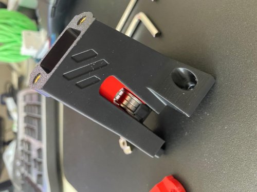
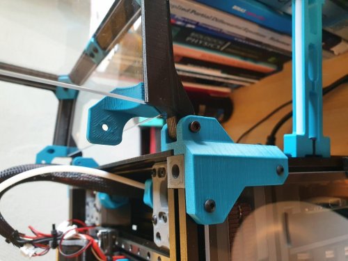
Wago Mount
Wago_Mounts
Wago 221 Lever Nuts are really cool, and easy to use (and not inexpensive). The 221-412 Lever Nut can be used to make your heater bed modular. You can get them here: https://www.amazon.com/Lever-Nuts-Compact-Splicing-Connector-Contains/dp/B093LQSQXG
There are also very nice mounting brackets for them. The one I based mine on was created by deepfriedheroin and is available here: V2 Bed Wagos
But, that mod assumes nothing else is going to be taking up that space. I am going to also use the purge bucket and brush mod, so I won't have enough area to take advantage of DeepFried's mount. So I made a smaller one, that mounts flush to the same extrusion the Z-stop is on.
I also added features!
It has an indexing tab on the back so it only requires one M3x8 SHCS bolt (and matching T-nut) to mount, and the indexing tab does not extend the entire length, just in case you want to push the edge past the end of the extrusion a bit for added space. It has a tiny area to wedge a flathead screwdriver in to pry the WAGO out if you need to, without having to work too hard. I printed this in PETG, but I imagine I will need to reprint in ABS once the Voron is working. Infill doesn't really matter I don't think, but I used 70%
Note: The live pic is an older version which works, but could be better. It's a good location example.
195 downloads
-
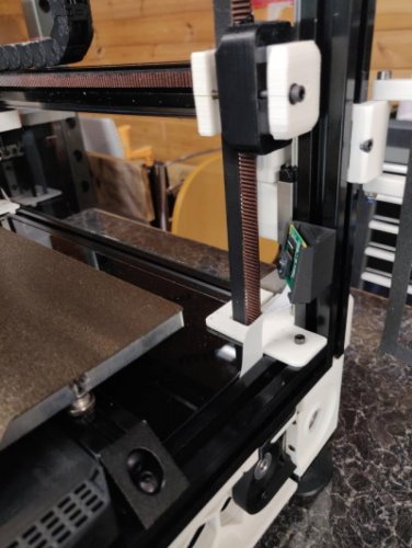
Switchwire Y Belt Tensioner
This mod for Voron Switchwires Y axis Belt tension, you don't need cut panels
Fasteners
2x M3x8mm SHCS 2x M5x10mm SHCS 1x M5x10mm BHCS 1x M5x16 up to 20mm for tensioner 2x M5 T-Nut (For 3030) 1x M5 T-Nut (For 2020) 2x M3 Threaded Insert Use Allen key for tensioning your belt, You can use brim while printing
212 downloads
(0 reviews)0 comments
Submitted
-
Voron Parts Logo for your VORON Printer
STL File
You can print this logo on your 3D printer. I have included base (0.64mm thick) in this stl file which you can print in base color (at 0.24 first layer + two 0.2mm layers) & change filament after 3 or 4 layers to your accent color. I changed filament after 4 layers. Use monotonic top layer infill to have uniform top layer of Black base. Check images below. Use VHB tape to stick it to back panel.
Image Files
Image files are included in high quality JPG & PNG format if anyone wants to print them on paper with traditional ink printer.
DXF File
DXF file is included if anyone wants to cut this on laser cutter out of Vinyl wrap. (Like I did, Shown in Images below)
885 downloads
(0 reviews)0 comments
Updated
-
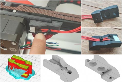
Filament Sensor for Dragon Mini AB
I wanted to create an invisible filament sensor inside the toolhead to check if the filament runs out or if there is a clog in the extruder gears. Tested on Dragon normal flow, not tested on Dragonfly, but it should work.
https://github.com/diego589/Mini-AB-Filament-Sensor/raw/main/Images/Comparison.jpeg
BOM
For both (before and after the extruder's gears)
2x digital hall sensor, it doesn't matter if it's latching or not. I'm using U18 7x 4mm ball bearings 4x 5mm x 3mm Round Neodymium Magnets 2x 10k ohm resistor Thin wires, 32 AWG recommended BOM If you only want a sensor before the gears:
1x Digital hall sensor 1x ball bearing 2x Magnets 1x resistor Thin wires BOM If you only want a sensor after the gears:
1x Digital hall sensor 6x ball bearings 2x Magnets 1x resistor Thin wires Tools
Multimeter Printed parts
[a]FS_Mid_Body.stl - Needed Recommended to print 2 copies of every hall sensor holder [a]FS_Cowling_Dragon.stl - Not needed at all, but print it if you don't want to sand it down (step 13) Assembly
Insert 6 balls in 1 Insert magnet in 1 Make sure that magnet is around 2mm down the tunnel, if not, then push it using filament or something similar Test your clearances by inserting filament, when there is no filament the magnet should be 2mm down the tunnel and when the filament is loaded, the magnet should raise up about 2mm Insert a magnet in 3, it should repel the magnet in 1. If you inserted it in the wrong orientation use an 1.5 or 2mm drill bit to remove it out of the hole Prepare hall sensor, solder resistor at no less than 10 cm from the sensor Test your circuit, move the hall sensor towards each magnets and check with a multimeter between GND and OUT, it should read 5v next to one and 0v next to the other Insert the hall sensor in [a]HallSensorHolder145-145.stl, then insert the holder with the sensor in 2 (small face of sensor pointing towards 3). DO NOT force it yet Load and unload filament and check with a multimeter if there is any variation, if the voltage doesn't change, rotate hall sensor and repeat If everything is working, push the hallsensor holder in place If it's not working, remove it and try with a different sensor holder, then repeat For the sensor that goes before the gears follow the same instructions but use just 1 ball bearing instead Bend the sensor pins until they are below the highlighted part (image below) Route your cable following the path as shown in the image below. If you didn't print [a]FS_Cowling_Dragon.stl you have to sand a path down yourself (black circle in image below) Choose any available pin on your board. In this case I am using RX2 and TX2 because they are right next to GND and +5v. See TestCode.txt
17 downloads
- diego589
- filament sensor
- (and 2 more)
(0 reviews)0 comments
Updated
-
BTT Smart Filament Sensor Mount
SLICER SETTINGS
4 Perimeters 40% Infill DISCLAIMER
You are responsible for your own actions.
CREDIT WHERE CREDIT IS DUE
I am unsure of the original designer of this part. If you know, let me know.
BILL OF MATERIAL
7g of Filament 2 M3x10mm SHCS for attaching the mount to the sensor 2 M3x6mm SHCS for attaching the mount to the frame 2 M3 T-nut152 downloads
(0 reviews)0 comments
Submitted
-
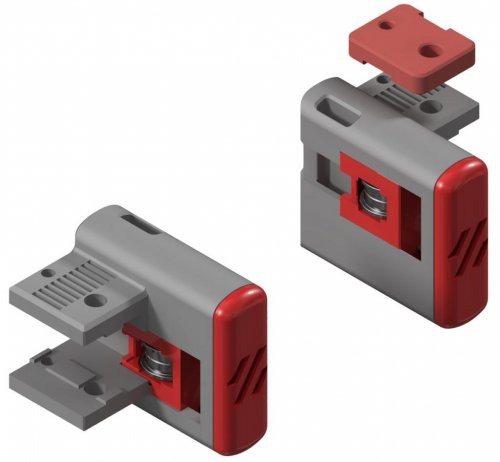
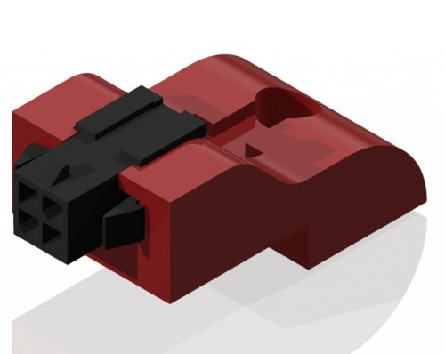
Input Shaper Skirt Connector
SLICER SETTINGS
4 Perimeters 40% Infill Supports are needed to support the panel mount DISCLAIMER
Make at your own risk. Worked for me, may or may-not work for you.
CREDIT WHERE CREDIT IS DUE
The outer housing and lock are a modification of meteyou's gcode_buttons mod
BILL OF MATERIAL
Roughly 4g of filament 6 Pin MicroFit3 Molex Panel Mount Connector (Molex Part #0430200608) 6 Pin MicroFit3 Molex Receptacle (Molex Part #0430250600)105 downloads
(0 reviews)0 comments
Submitted
-
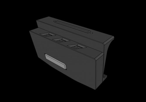
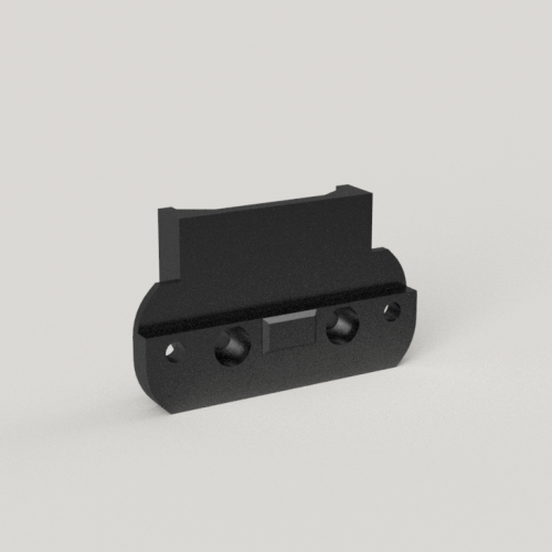
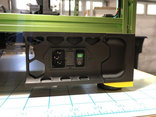
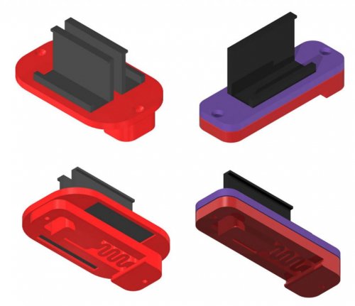
Trident Schurter Power Inlet
Trident Inlet Skirt For Schurter DD11.0124
This is a modified inlet skirt for VORON Trident to install a Schurter DD11.0124 or similar power inlet.
Print using standard VORON print settings. You'll need the same 2 heatset inserts and 2 FHCS screws as the stock filtered inlet to mount this.
17 downloads
(0 reviews)0 comments
Submitted
-
Front Idlers
Longtime Testing Phase! Update (02.09.21): STL's available for testing! Please print and report issues! Update (03.09.21): Added7,128 downloads
-
Stiffer DinMount
Stiffer DIN Mount
Credits:
Voron-Team: Its the default generic DIN Mount, but modified! Printing:
Default voron settings, correct orientation, no supports needed! Bom:
2x M2x10 Self-tapping Screw Description:
Stiffer generic Din Bracket (same as the one for the pi, but it sits much tighter on the din rail. I found the voron ones a bit wobbly on the din rails) You can use this bracket for everything else. Pictures:
248 downloads
(0 reviews)0 comments
Submitted
-
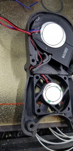
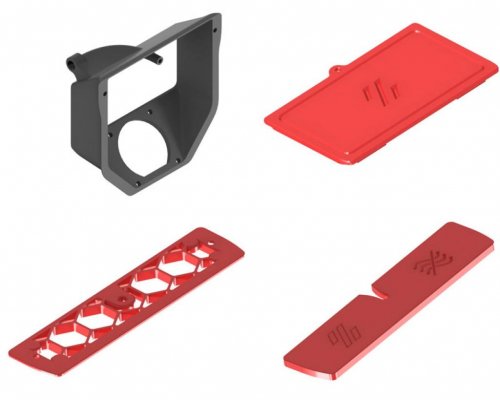
Exhaust 90
Exhaust 90° Mod (Guided max angle radius for smooth filament sliding)
Credits:
Voron-Team: Its the default 2.4 Exhaust, but modified! @falo2k: Magnetic Grill Cover (Awesome guy, my Grill Cover is exactly his Grill Cover, only with a recessed filament hole, to match the Exhaust 90° Mod.) So all credits to him! Printing:
Default voron settings, correct orientation, no supports needed! Bom:
6x M3 heat inserts 4x M3x25 SHCS (Fan Screws) 2x M3x8 BHCS (Grill Screws) 4x 6x3 Magnets (Grill) 4x 6x3 Magnets (Cover) Foam Tape, please check falo2k for this Magnetic Grill Cover PTFE Tube (3mm ID / 4mm OD) 2x Mount Pieces Description:
Exhaust Mod with as less as possible ptfe tube bending. The ptfe tube is guided. I highly recommend an 4mm OD and 3mm ID ptfe tube. But all other ptfe tubes fits either. The magnetic cover parts are a nice touch. Housing: Only modified for better printability. So no supports needed and it's easy printable. You don't have to use this whole set. The housing is compatible with all351 downloads
(0 reviews)0 comments
Submitted
-
Wagomount 221
Wago 221 DIN Mount
Credits:
Voron Team :-) Printing:
Tolerances are very tight, print only with calibrated flowrate Default voron settings, correct orientation, no supports Bom:
2x M2x10 Self-tapping Screw Description:
Simple design for 1/2/3 x 221 5-port wagos. I didn't found anything here that is mountable to din rails, so i made one simply. The wagos are sitting in there pretty extreme, so you don't need to worry about opening66 downloads
(0 reviews)0 comments
Submitted
-
Misumi Led Corners
Misumi LED Corner Clips
Credits:
Eddie from the Voron-Team (From his awesome Misumi Led Clips) You get his LED Clips in Discord, he didn't published it to Voronusermods sadly :-( Printing:
Default voron settings, correct orientation, no supports Bom:
Nothing Description:
Corners for the awesome Led Clips from eddie, to hide the wires and one blanklet. No need to cut or recable your wiring, this clips are meant to hide already existing cables. You will find out how it works once you print and try it :-) You can modify their Z-Size as you need, simply scale it. Don't scale below 75% and above 150%. Below 75% the wires will probably not fit on the exit. And above 150% it will just have an big wire exit and will look weird. Pictures:
213 downloads
-
ADXL Skirt Dupont
ADXL Skirt Connector mount (Dupont Version)
Credits:
@alch3my: The plug is based on his skirt insert base, which works amazing btw. Printing:
Tolerances are very tight, print only with calibrated flowrate Default voron settings, correct orientation, no supports Bom:
2x m3x8 or m3x12 screws. 3x 3-pin Dupont 3x 4-pin Dupont 1x 8-pin Dupont (for adxl itself) Some cables (im using 30 20cm) Description:
Should be self explanatory in the pictures! The ADXL Dragon mount is available here: https://github.com/Ramalama2/Voron-2-Mods/tree/main/ADXL_Dragon_Plug Pictures:
277 downloads
(0 reviews)0 comments
Submitted
-
(0 reviews)
0 comments
Submitted
-
Bedhole Plug
Buttom Plate Bedhole Plug
Credits:
Everyone that can draw a Circle :-) Printing:
Default voron settings, correct orientation, no supports Bom:
Nothing Description:
It's by default for Ø15mm hole on a 3mm plate, but you can simply scale it in your slicer to your needs. Pictures:
59 downloads
(0 reviews)0 comments
Submitted
-
ADXL Dragon Plug
Adxl Mount Heatblock (Dragon Version)
Credits:
@tzeman: https://www.thingiverse.com/thing:4897289 (V6 Plug) He inspired me for this Dragon Version! Printing:
Tolerances are very tight, print only with calibrated flowrate To be safe, scale it to 102% in all dimensions. (It's designed to be scaled between 100145 downloads
(0 reviews)0 comments
Submitted
-
AB Plug Microfit
AB Motor Plug (Microfit)
Credits:
Myself xD Printing:
Default voron settings, correct orientation Supports are needed (Check Pictures below) Bom:
M3x8 M3 T-Nut Microfit 3.0 4-Pin Description:
LDO motor steppers comes with that prewired steppers (which doesn't have a plug), so this is exactly for making a25 downloads
(0 reviews)0 comments
Submitted
-
AB Plug JST XH
AB Motor Plug (Jst-XH)
Credits:
Myself xD Printing:
Default voron settings, correct orientation Supports are needed (Check Pictures below) Bom:
M3x8 M3 T-Nut JST-XH 4-Pin Description:
LDO motor steppers comes with that prewired steppers (which doesn't have a plug), so this is exactly for making a75 downloads
(0 reviews)0 comments
Updated
-
Picam Corner
Picam corner mount
About the only place I found to mount the picam with a view low down of the bed. This was inspired by the v0 design by xbst
Hardware
A single m3x8 bolt and t-nut A suitable length of picam ribbon cable
274 downloads
(1 review)0 comments
Submitted
-
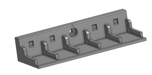
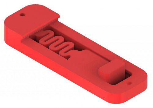
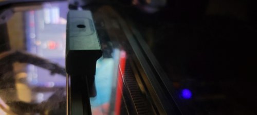
LED Bar Clip
This simple LED clip allows you to mount LED Strip (16.6mm spacing between LEDs) to your 2020 Extrusion. It has baffles to block the light from shining in your face. Print one per LED!
130 downloads
(0 reviews)0 comments
Updated
-
Huvud Chain Mount
Huvud Cable Chain Mount
A mount for the Huvud toolhead board that mounts on the back for cleaner wiring but still allows for the use of a cable chain. Moves the assembly 6mm up to clear the chain at X0 as it rises onto the X joint. Has space for airflow between the motor and the Huvud to keep temperatures reasonable and includes a wire tie spot for wires coming out of the chain. Current only configured for 3-bolt generic chains. Works for both Clockwork and LGX.
Parts Required:
(3) M3 heat set inserts for the chain (3) M3x6 FHCS to mount the chain (2) M3x25 BHCS to mount to the motor (4) M3x8 SHCS to mount the Huvud. Installation:
Remove the printed support. Install the 3 heat set inserts. Remove the upper two screws of the motor. Install the mount with the two M3x25 BHCS. Attach the Huvud with the four M3x8 SHCS. The screws will thread into the plastic. Be sure to check clearance between electrical components and the M3 BHCS screws underneath Attach the chain with the three M3x6 FHCS. Designed for the Trident but will also work on a V2.4, just be conscious of clearance to the Z chain.
31 downloads
- 120decibell
- v1.8
- (and 1 more)
(0 reviews)0 comments
Submitted
-
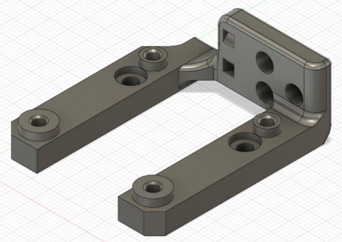
TophatHingeV0.1
I really like the design of the tophat of the V0 but wanted to be able to open and close it easily.
This is a hinge for the tophat of the V0, without changing the aesthetic. It uses modified panel mounts and tophat parts. I've added panels mounts for thicknesses of 2, 2.5 and 3mm. Also the lower corner clips are adapted to allow for the rotation. All parts can be printed without support.
Printed and tested: the tophat is relatively stable and stays in the open position.
Requirements:
4 x M3x20
6 x M3x12
1,085 downloads
(0 reviews)0 comments
Submitted
-
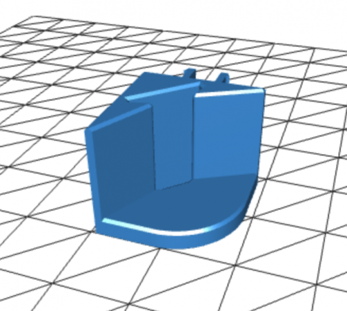
Block Handle V0.1
This is a simple handle design that replaces both side top most panel mount clips. The idea was to make a handle that doesnt require nuts to be added to the frame of the v0.1. Uses a single M3x12.
12 downloads
(0 reviews)0 comments
Submitted