-
TeamFDM.com is an UNOFFICIAL companion site for the DIY Voron 3D printer community. For official docs and final source of truth, visit the Official Voron Discord or the Voron Github
Printable Voron User Mods
Voron User Mods, or "UserMods", are a collection of community created and Team FDM curated modification for Voron Printers. All of these mods are available on the VoronUsers Github repo and unless otherwise specified follow the Voron communities GPL3.0 Licensing. Use any Mods at your own risk, if you make modification please share them on the VoronUsers repo.
Mod Authors: Have a Voron mod? Upload it at TeamFDM.com and let us know you're the author. We will ensure you can update and curate your files for more feedback! Please include tags for what Voron, or extruder your mod is compatible with.
660 files
-
Strain Relief W Microfit
Strain Relief to Mount a Microfit 10 pin panel mount connector. Pics have bent cable tie from previous iteration, for printability without supports the STL included prints without support in your slicer. The hole for the connector has a V shaped built-in support that must be cut away to insert connector. Easily snips away with your flush cutters.
9 downloads
(0 reviews)0 comments
Submitted
-
(0 reviews)
0 comments
Submitted
-

FlyF407ZG
Voron 2.4 Hinge Mod for 3mm Doors with 3mm Foam This is designed for 3mm door panels with 3mm of foam. I used the laser cut panels from Printed Solid which are 3.175 (1/8
2 downloads
(0 reviews)0 comments
Submitted
-
Microswitch Endstop
Voron 2.4 XY Microswitch Endstop for PCB
POD for use with the Microswitch endstop pcb board for X and Y axes.
Check Microswitch_Endstop for the microswitch pcb.
35 downloads
(0 reviews)0 comments
Submitted
-
WansviewCameraMount
Wansview 1080p Webcam Mount
This is a mount designed for a resonably priced webcam that's an alternative to the common Logitech choices. The mount is designed to interface with the Voron 2.4 spec extrusions and uses common mounting hardware (2x m3x8 SHCS or BHCS, 2x m3 spring nuts).
Installation:
Remove the black sticky covers indicated by the two arrows Remove the mounting hardware with a phillips head screwdriver
Install the new mount reusing the OEM hardware; position as indicated so your image is oriented correctly (note: get the screw snug enough to hold the camera in place by friction yet still allow you to make small adjustments after install).
install centered on top extrusion with your choice of m3 spring nuts and m3x8 screws. Enjoy seeing your printer printing
79 downloads
-
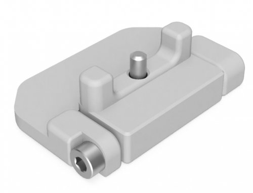
Duet 3 6HC Din Bracket
Please use the generic PCB DIN Clip and mount these on top.
Image coutersy of medicusdkfz
6 downloads
(0 reviews)0 comments
Submitted
-
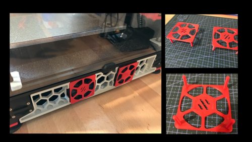
60mmFanCover
60mm Fan Cover for Controller Fans
I took inspiration from StvPtrsn to create an accent cover for the 60mm fans cooling the electronics enclosure. His design is integrated with the skirts and would likely be much more structrually sound; my goal was to make a simple cover that you can insert from the outside without flipping the printer over. It is attached with a small quantity of 3M VHB tape in each of the corners.
Installation:
Apply a small piece of VHB tape on the body of the fan in each of the four corners Insert the pegs of the cover into the fan holes Hold for 30 seconds to give the VHB tape time to bond52 downloads
(0 reviews)0 comments
Submitted
-
(0 reviews)
0 comments
Submitted
-
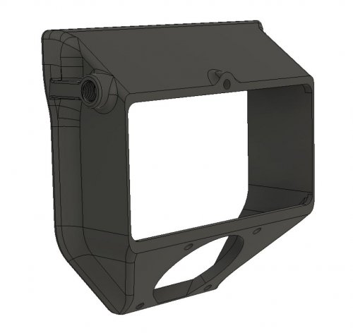
Exhaust Housing Side Fitting
Exhaust housing with the bowden fitting moved to the side
Moves the bowden fitting on the exhaust housing 90 degrees and to one side of the housing. This allows the printer to stand with its back closer to a wall. The only thing that has been changed from the original is the location of the bowden fitting.
If you want the bowden to be on the other side your printer, just mirror the model in your slicer.
42 downloads
(0 reviews)0 comments
Submitted
-
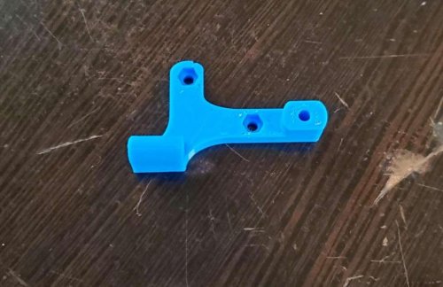
Hartk Mount Galileo
Simple mount for Hartk board for galileo.
Used to mount the Hartk board using the cover screw mounting locations for the galileo. Uses 1 m3 heat insert and 2 captive M3 nuts. Board is available for purchase here Github for the board located here
Thanks to Hartk for making an amazing board for our voron needs.
48 downloads
-
VEFACH
All STL CAD files. Please take a look at the instructions listed in the main README before printing. Feel free to modify the parts :)
431 downloads
- kevinakasam
- filter
- (and 1 more)
(1 review)0 comments
Submitted
-
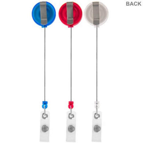
Badge Retractor Mount
Badge Retractor Mount
Just a simple little mod to keep the bowden tube out of the way using a badge retractor. Available in multiple angles.
Designed for this style of badge retractor, but may work with others:
(You probably have one in a drawer somewhere)
25 Degree
104 downloads
(0 reviews)0 comments
Submitted
-
Short Z Joints
Shorter Z joints for Voron 2.4
This mod reduces the size of the Z joint stack by 12.5mm.
The intent is to increase gantry stability by reducing the leverage on the Z ball joints while throwing the toolhead around.
This is only tested with microswitch XY endstops. There is no hall effect magnet slot, though you may be able to affix one to the upper right screw head.
To use this mod, you will need:
4x M5x30 SHCS/BHCS
4x M5x20 BHCS
4x M3x20 SHCS
4x M5 nylon lock nuts (optional*)
You can use standard M5 nuts as per the original config, however I prefer nylock nuts here.
Side by Side
Cross Section
16 downloads
(0 reviews)0 comments
Submitted
-
15x15 Drag Chain End
15x15 Drag Chain End
End pieces for 15x15 drag chains. Designed around Cloudray China chains, but will likely work with other chain brands too.
27 downloads
(0 reviews)0 comments
Submitted
-
C920 Mount
Slim Mount for Logitech C920 Webcam
Inspired by PhilLeMint's mount
BOM
Qty Item 1 Logitech C920/C920s Webcam 2 M3 t-nuts 2 M3x8 SHCS Instructions
Disassemble webcam using instructions seen here stopping after step 5 Remove the metal arms from the factory supplied mount Push the plastic bushings on the metal arms into the holes on the printed mount Reattach the metal arms to the webcam Reinstall lens cover, side covers, and stickers Use two M3 t-nuts and two M3x8 SHCS to mount the webcam to the inside of the top front extrusion193 downloads
-
V0 Beltchain
These files are for printed replacement chains for the z-axis on V0 printers. The original
42 downloads
(0 reviews)0 comments
Submitted
-
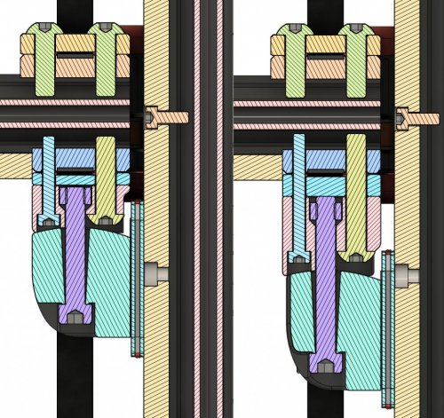
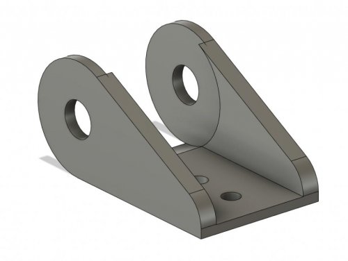
Z Drive Motor Mount
Simplified Z Drive Motor Mount
Issues with original design
I have had issues with alignment on the 188mm Z drive belts causing the belt to rub on the motor pulley. I found that the motor mount was difficult to align squarely with the frame and this was causing the pulley misalignment. I haven't noticed any print issues caused by this misalignment but it will prematurely wear the belts, not to mention that the rubbing noise is not something I'm happy to live with on a £1200 printer.
I found the problem was caused by the design of the tensioner which means there isn't much space for the alignment key feature used to align the motor mount into the aluminium extrusion of the frame (shown highlighted in blue).
Simplified design
I have simplified the design by combining the tensioner into the motor mount. Belt tensioning works by a small protrusion which pushes against the side of the Z drive housing (inspired by the original design). I have tried to keep the belt tension the same as is acheived in the original design. Assembly is surprisingly straightforward and cuts out a few of the steps required with a separate tensioning arm.
Combining the tensioner into the motor mount has created space for the extrusion slot key to be extended across the entire face of the motor mount, allowing for the key to work more effectively in aligning the motor mount squarely to the frame and ensuring that the motor pulley is aligned with the belt and 80T driven pulley.
The only downside I see is to the 'cool factor' The original design looked pretty awesome with the contrast of the tensioner handle, now it is a bit boring looking if I'm honest but it is very functional. I'll leave it up to you to decide whether its worth the change.
69 downloads
(0 reviews)0 comments
Submitted
-
V0 Sherpa Mini Direct Drive
# V0 Sherpa Mini Direct Drive Mod
Requirements
Printed parts included in STL One fully assembled Annex Sherpa Mini (see: https://github.com/Annex-Engineering/Sherpa_Mini-Extruder ) Notes
This is a direct drive mod using the Annex Sherpa Mini. The existing pocketwatch extruder can be broken down to use the TL BMG guts, if desired, for the Sherpa Mini.
Wire routing should be merged together in the slot provided, and wires should exit behind the motor.
Note: This hotend mod is for the Dragon hotend only. Feel free to modify for V6/Mosquito if desired. Fan shrouds should be identical.
80 downloads
(0 reviews)0 comments
Submitted
-
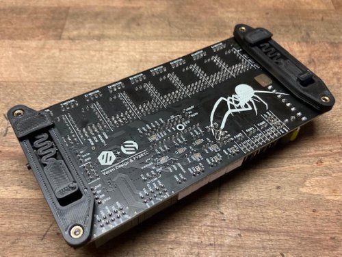
FYSETC Spider DIN Mount
FYSETC Spider DIN Rail Mount
for horizontal or vertical mounting
Required materials:
for horizontal mounting:
1x printed bracket terminal side of the Spider Board: spider_bracket_horizontal_terminal.stl 1x printed bracket USB-Port side of the Spider Board: spider_bracket_horizontal_usb.stl for vertical mounting:
1x printed bracket terminal side of the Spider Board: spider_bracket_vertical_terminal.stl 1x printed bracket USB-Port side of the Spider Board: spider_bracket_vertical_usb.stl for both types:
4x printed spacers: spider_spacer_x4.stl 4x M3 x 8mm BHCS/SHCS 4x M3 x 4mm threaded inserts Assembly:
Put the four screws through the Spider Board mounting holes and screw it into the spacers. The spacers are intentionally tight so that you don't have to fiddle the spacers between the board an the DIN Mount.
Then screw the board on evenly on the mounts.
Note: The mounting holes on the Spider board are very tight for M3 Screws. I drilled the holes out with a 3.2mm drill bit, but don't encourage anyone to do so, because - reasons.
Disclaimer: It is your printer. If you do this and something breaks or if someone gets hurt, it is fully your responsibility. I take no responsibility.
In case of doubt ping me on Discord hoschi#0238
485 downloads
(0 reviews)0 comments
Submitted
-
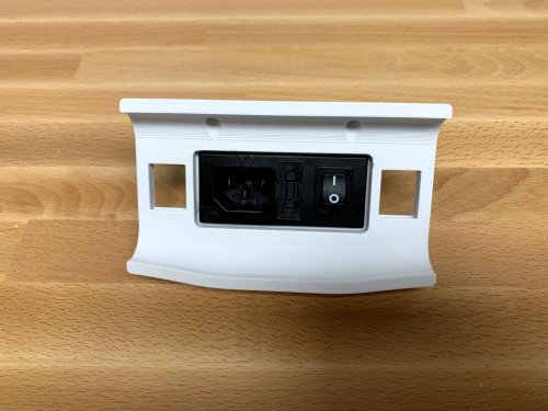
Plug Panel Generic
Voron 2.4 Plug Panel Mod for Generic Unfiltered Modules
OVERVIEW:
Plug panel which fits any modules that have 66mm x 27mm cutout, such as the Delta 06A2 and Qualtek 761-18.
8 downloads
(0 reviews)0 comments
Submitted
-
UHP PSU Bracket Clip
UHP PSU Bracket
Overview
This is a DIN 3 Rail (35mm W) bracket for the Mean Well UHP-200 series powersupply edited from the official Voron Mean Well LRS series powersupply bracket. This design has 2 versions, one with an embedded nut and one with an heat-set insert.
The double rail version is made for the spec rail distance and doesn't work for other distances.
I added the CAD files so editing to other sizes should be wasy. If you can't do it yourself hit me up on Discord.
BOM
4x M3x6 BHCS. 4x M3 Hexnut. OR 4x M3 Heat set inserts (M3x5x4). Printing instructions
No special printing instructions. Part doesn't have to carry much weight.
Assembly instructions
Personally I added a little glue to the embedded nut to make it stick, but this is not needed.
For the double rail version you're supposed to screw the UHP to the last clip after attaching the clips to the rail. Making a version that could be attached without this lost gripping strength or made the part harder than it needed to be.
Questions
Reach me in Voron's Discord @MarcPot#3983 if you have any questions.
Images
107 downloads
(0 reviews)0 comments
Submitted
-
Skirt Mods
MarcPot Skirt Mods
WARNING I HAVE NOT TESTED THE 250 and 350 VERSIONS. PLEASE TELL ME IF YOU DID AND I'LL EDIT THIS WARNING.
WARNING to give the hour counter enough clearance in the 250 version the hour counter will overlap the plug panel, this should not matter. But again, I haven't tested it.
I have checked them all in my slicer and they sliced correctly.
Also, if you think the keystones don't fit, try rotating them.
Overview
These are my mods for the Voron V2.4 Skirts. They are modifications of the official Voron V2.4 skirts.
BOM
Keystone inserts. OR
M3x8 SHCS. Hour Counter Printing instructions
No special printing instructions. They are skirts.
Assembly instructions
No special Assembly instructions. They are skirts.
Configuration instructions
For the keystones there are no special configuration instructions. They are plug
193 downloads
(0 reviews)0 comments
Submitted
-
M3 Door Hinges
Door hinges mod for v2 which use m3 schrews as shafts instead of print-in-place solution
82 downloads
(0 reviews)0 comments
Submitted
-
V0 LED Hinge
V0 LED Hinge
This modification was designed to accomodate a Neopixel Jewel (7) in the top right hinge of the front door. A channel is present in
50 downloads
(0 reviews)0 comments
Submitted
-
V0 TopHat Mini 12864
V0 TopHat Mini 12864
I wanted to have the ability to use the V2 display with my V0, so designed this mod to allow for it. Although they look similar, the Mini 12864 front and back case files have been slightly altered to accomodate this design.
#
Config for SKR Mini E3 V2
Below are the pins that I used in Klipper for the display and a really bad representation of the wiring I performed.
[display]
lcd_type: uc1701
cs_pin: PB9
a0_pin: PB8
rst_pin: PB15
encoder_pins: ^PB5,^PA15
click_pin: ^!PA10
contrast: 63
spi_software_sclk_pin: PA5
spi_software_mosi_pin: PA7
spi_software_miso_pin: PA6
[neopixel fysetc_mini12864]
pin: PA9
chain_count: 3
color_order_GRB: False
initial_RED: 0.3
initial_GREEN: 0.3
initial_BLUE: 0.5
#
Mount It!
M3 threaded inserts are used in the lower wall of the back case file, this allows for M3 screws to be ran through the TopHat pieces into the case, resulting in a solid configuration.
The parts are in the correct orientation for printing.
85 downloads
(0 reviews)0 comments
Submitted
.thumb.jpg.8e84033ccda44c57febd99ef7338ef1f.jpg)