Jump to content

15 Screenshots

  • Like 21
  • Voron FTW! 14
  • Thanks 2

Recommended Comments


On 6/2/2024 at 6:35 AM, atrushing said:

对不起,这花了一段时间。我为 Mini Stealth v2 制作了新的十六进制图案 .stl 文件,并找到了一个视频,该视频应该可用于在 Bambu Studio 中设置双色图案打印。前一分半钟不适用,因为他是从转换后的 .svg 文件创建嵌体。

2024-06-02-002023_992x880_scrot.thumb.png.42b9c6c42a6a1bb4b2505341a88c5721.png

Mini_Stealth_v2_Hex_Pattern.stl获取信息... Mini_Stealth_v2_Hex_Pattern_UHF.stl获取信息...


Link to comment
Share on other sites

Hi, Thanks for the awesome project, I've been following for a long time! I was wondering are the XY_Joint files required for the the Voron 0.2 or just the X-Carriage Mount? 

Thanks!

Link to comment
Share on other sites
9 hours ago, xen0 said:

Hi, Thanks for the awesome project, I've been following for a long time! I was wondering are the XY_Joint files required for the the Voron 0.2 or just the X-Carriage Mount? 

Thanks!

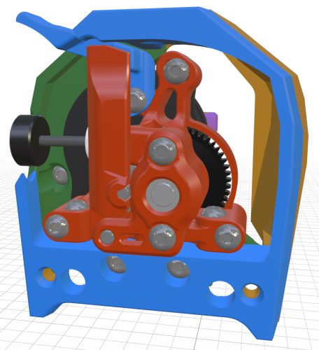
They are needed for the new V0.1/V0.2 x-carriage mount. The new x-carriage (grey below) is wider so that I could add a vertical rib on each side of the MGN7/9 linear carriage making it much more rigid. The original printed x-carriage was always the most flexible part of the toolhead installation. The pink spacer part is the no-drop nut holder. It wraps around the end of the 1515 profile and holds all three of the M3 square nuts for each side. The new X/Y Joint upper L/R pieces are just cropped closer to the stock screw position to make the needed clearance. You could also mechanically cut/file the stock X/Y uppers in place to make the enough room for the x-carriage.

20240614_071206_.thumb.jpg.680d1a43132b71c9a25fe73dd37472d9.jpg

If you are using a CNC aluminum x-carriage then you shouldn't need to change the X/Y Joint pieces but I can't guarantee that the machined x-carriages will clear the 4010 blowers of the Mini Stealth.

Link to comment
Share on other sites

hi guys.

normally i do the mods myself however the lack of a step file left me crippled.

i'm trying to mount this on a u20 with a front facing mgn9c linear rail. Kind of cramped for space seeing that i would like to keep it as close to the rail as possible. Is there an orbiter crop top version with the a bl touch mount on the side? like the diffIR mount?

in exchange id like to offer up a reverse engineered core for orb 2.0 to dragon.

thank you in advance

ministealth v2 orbiter 2_dragon core.stp

Link to comment
Share on other sites

hi guys.

normally i do the mods myself however the lack of a step file left me crippled.

i'm trying to mount this on a u20 with a front facing mgn9c linear rail. Kind of cramped for space seeing that i would like to keep it as close to the rail as possible. Is there an orbiter crop top version with the a bl touch mount on the side? like the diffIR mount?

in exchange id like to offer up a reverse engineered core for orb 2.0 to dragon.

thank you in advance

Link to comment
Share on other sites
36 minutes ago, nvanstaden said:

hi guys.

normally i do the mods myself however the lack of a step file left me crippled.

i'm trying to mount this on a u20 with a front facing mgn9c linear rail. Kind of cramped for space seeing that i would like to keep it as close to the rail as possible. Is there an orbiter crop top version with the a bl touch mount on the side? like the diffIR mount?

in exchange id like to offer up a reverse engineered core for orb 2.0 to dragon.

thank you in advance

Sorry about the lack of a .step file. It is all raw mesh-editing in Blender for me..

This BL Touch mount fits onto the Diff IR shroud with a pair of M2.5x6 flathead screws.

2024-06-23-095843_1206x910_scrot.thumb.png.70d30b226864a7b5018df7550fe69ea8.png

I looked up the Alfawise U20 and the gantry looks similar enough to the Ender 3 that you might be able to use the MGN9 Switchwire style x-carriage I have recently added to the repo. It stays pretty close to the 2020 extrusion and assumes that the back of the MGN9 rail is mounted 4.5mm from the front of the extrusion. There is more information about these x-carriages in this comment thread but the GitHub files are more current.

There is already a core for the Orbiter 2.0 with the Dragon hotend but thanks for the offer!

  • Like 1
Link to comment
Share on other sites

you sir are a gentleman and a scholar.

thank you very much. the attached step file is only for those that wish to incorporate it in their drawings for easier constraints when doing the assembly.

for the bl touch, i assumed that it mounted there. do you think the shroud would still fit with the orbiter if it was printed mirrored?

also for the carriage, from what i have seen of the switchwire style carriages is that the belt mounting is different. i only have a single belt so ill just make my own. however i may convert this to switchwire style in the near future. and you are correct, the gantry has been retrofitted with the same parts as the ender to accommodate a belt driven dual z axis. 

im very excited about the work you have done here, the dragonburner has too much plastic and parts in my opinion, and maintenance seems way easier on yours. truly a work of art.

  • Thanks 1
Link to comment
Share on other sites
6 hours ago, nvanstaden said:

for the bl touch, i assumed that it mounted there. do you think the shroud would still fit with the orbiter if it was printed mirrored?

The base of the Orbiter 2.0 sticks out on one side so the section in red would need to stay where it is. Also, the ducting for the 4010 blowers is directional so mirroring would block most of the airflow.

2024-07-12-195154_868x832_scrot.thumb.png.4879ecf85c7bb006894c0542f6f7c6ad.png

I made the shrouds modular in Blender to make it easier to maintain all of the different versions so it is simple enough for me to mirror some of the features without breaking anything else but I will still need to adjust some of the mesh like the holes for Allen wrench access.

2024-07-12-200630_982x538_scrot.png.2107fb46281fad71347a4379bf28b021.png

6 hours ago, nvanstaden said:

also for the carriage, from what i have seen of the switchwire style carriages is that the belt mounting is different. i only have a single belt

The Switchwire style mounts that I made for the Ender 3 only use one belt and centers it on the bottom of the 2020 extrusion. I started with a Switchwire x-carriage and modded it for an Ender gantry with the MGN9 or MGN12 mods. Check through this and the next few comments in the thread for more information.

20240616_113204.thumb.jpg.e07a4672f4956baa24def36312ebcc33.jpg

Link to comment
Share on other sites

omg you are too nice.


thank you very much!

i also checked and mine is mgn9h. i confused it with my other other printer that is 9c so this carriage will be perfect.

i love that wedge idea.


do you have link for donations?

  • Like 2
Link to comment
Share on other sites
41 minutes ago, nvanstaden said:

omg you are too nice.


thank you very much!

i also checked and mine is mgn9h. i confused it with my other other printer that is 9c so this carriage will be perfect.

i love that wedge idea.


do you have link for donations?

Glad to help and that there is an x-carriage version that will work for your printer! I wonder if I should (or even can) make versions for MGN12C and MGN9C linear carriages..

The wedge was a fun solution. It took a while of staring at the 3D model trying to imagine how to fit clamp blocks and screws before I figured it out.

I have a paypal.me link and would greatly appreciate any support!

  • Like 2
Link to comment
Share on other sites

ill c if i can rework that to maybe carry the bltouch even though it may push the head forward a bit.

thank you for your effort.

  • Like 1
Link to comment
Share on other sites

hi guys.


maybe my african is shining through but i get a hole on the model when im slicing.

the only time there is not is if the line width is 0.2mm

ami i doing this wrong?


this is on the crop top shrouds for orbiter 2.0

all of them


hole.PNG

Edited by nvanstaden
Link to comment
Share on other sites
10 hours ago, nvanstaden said:

hi guys.


maybe my african is shining through but i get a hole on the model when im slicing.

the only time there is not is if the line width is 0.2mm

ami i doing this wrong?


this is on the crop top shrouds for orbiter 2.0

all of them

Apparently, this is true across every single shroud. I re-used as much geometry as possible..  This is how Prusa Slicer handles that feature even with Arachne turned on.

2024-07-19-074722_1084x696_scrot.thumb.png.9156a5cc973c0138fde2463c7823c60f.png

I have never noticed it before in the final prints though.

20240719_074832.thumb.jpg.326a782c60ba7640844dd1345769b8fe.jpg

I will add this to my Mini Stealth ToDo list of improvements.

Link to comment
Share on other sites

ok good so its not just me. i was starting to feel really stupid.

i assume it does not show on some of the prints due to the slicer using it as a z seam and it kind of fills it out.


it only becomes really apparent like when im printing with pacf and a 0.6 nozzle.


on a side note, im having hell with the overhang in the first 60 layers with abs. trying a different filament today. fingers crossed.

Link to comment
Share on other sites
1 hour ago, nvanstaden said:

it only becomes really apparent like when im printing with pacf and a 0.6 nozzle.

That would certainly exasperate the thin walls problem.

1 hour ago, nvanstaden said:

on a side note, im having hell with the overhang in the first 60 layers with abs.

If you're printing the ABS in an enclosed printer, go ahead and bump up the part cooling. I had major ABS curling issues on overhangs until I figured that out.

Link to comment
Share on other sites

yeah i have had it up to 100% in tests. was using polymaker abs lime but switched to galaxy black now. seems to be going better.

i modified the gcode to turn the fan down to 30% when im past layer 60 so i only get the fan at full blast when i need it.

printing super slow too.

it seems to have been the filament though, also its humid AF. ihave my dehumidifier running in the enclosure as well and the filament is in a dry box.

summer printing in montreal sucks.

IMG_20240719_123340_6.jpg

Link to comment
Share on other sites
21 hours ago, nvanstaden said:

hi guys.


maybe my african is shining through but i get a hole on the model when im slicing.

the only time there is not is if the line width is 0.2mm

ami i doing this wrong?


this is on the crop top shrouds for orbiter 2.0

all of them


hole.PNG

I would advise against using 8-9 walls in an attempt to make the part as solid as possible. Even though you're 3D printing plastic... the same rule of uniform wall thickness in injection molded parts still applies as the more mass your part has the more it will want to warp/distort as it cools. 4 walls and 30% infill is plenty strong and will net you better parts. 

  • Like 2
Link to comment
Share on other sites

oh no my dear sir. 

i was just screwing around here to show the hole.

those settings are for a specific part that we use in our machines.

i usually dont surpass 4 walls and mostly do 20% infill.

  • Like 1
Link to comment
Share on other sites
On 7/18/2024 at 9:05 PM, nvanstaden said:

hi guys.


maybe my african is shining through but i get a hole on the model when im slicing.

the only time there is not is if the line width is 0.2mm

ami i doing this wrong?


this is on the crop top shrouds for orbiter 2.0

all of them


hole.PNG

As part of a larger update, I have fixed these thin sections on all of the shrouds and pushed the change to GitHub.

  • Like 1
Link to comment
Share on other sites

Hi Maestro,

Can you please check the Status_LED_carrier.stl - I think it is missing a hole.

On your Git Hub at the first photo you can see the rear of the neopixel LED, so that means there must be a hole for the light to shine through. Or am I seeing it wrong?

Have you got a .step file of the whole thing, I am totally unfamiliar with Blender so cannot use the example.blend file.

I'd like to see how it's put together, it's not so clear in places.

TIA

TAD

Link to comment
Share on other sites
54 minutes ago, TitusADuxass said:

Hi Maestro,

Can you please check the Status_LED_carrier.stl - I think it is missing a hole.

On your Git Hub at the first photo you can see the rear of the neopixel LED, so that means there must be a hole for the light to shine through. Or am I seeing it wrong?

Have you got a .step file of the whole thing, I am totally unfamiliar with Blender so cannot use the example.blend file.

I'd like to see how it's put together, it's not so clear in places.

TIA

TAD

Sorry, I don't have any .step files. I edit everything as raw meshes.

The LED carrier should be printed in white or clear (PET should be fine here) and the Neopixel  will shine through it pretty well. I always use white ABS for both the carrier and the diffuser and it still shines through enough for me.

2024-08-08-170632_698x704_scrot.png.ae0489e4c92b956bb56d26fddd297569.png

I have attached a version with a hole if you would like to give it a try. Just as a reference though, the Stealthburner LED carrier has a solid front as well, and their diffuser is much thicker than mine.

2024-08-08-171907_324x303_scrot.png.6d7781818555b61ec2e22b5c4556cd52.png2024-08-08-172151_333x208_scrot.png.efefb12fcf971921cdcfa7107f7e8f26.png

Here is another picture showing the carrier (on the older Mini Stealth) that might help you visualize the assembly. That version was solid in front too.

20221014_222250.jpg

Status_LED_carrier_holey.stl

Link to comment
Share on other sites

Join the conversation

You can post now and register later. If you have an account, sign in now to post with your account.

Guest
Add a comment...

×   Pasted as rich text.   Paste as plain text instead

  Only 75 emoji are allowed.

×   Your link has been automatically embedded.   Display as a link instead

×   Your previous content has been restored.   Clear editor

×   You cannot paste images directly. Upload or insert images from URL.


User Feedback

×
×
  • Create New...