21 14 2 Details Changelog 0 Questions 643 Comments 3 Reviews 1 Tutorial Support Recommended Comments Prev 3 4 5 6 7 8 9 10 11 12 13 Next Page 8 of 26 atrushing 994 Posted February 20, 2023 Share On 2/14/2023 at 4:44 PM, crazypenguin said: I'm using a Orbiter 2.0 and Dragonfly BMO hotend, so this mod is a perfect fit. Is there a possibility for a BL-Touch attachment? It turns out that the BL-Touch will fit into the Orbiter version of the Switchwire x-frame pieces! The BL-Touch just slots right in between the two halves and its tabs keep it in place. I would have to change offsets for it to fit with the other hotends or in a V2.4/Trident so I will attach the files here and not in the downloads section. The new Biqu MicroProbe looks like it will be a lot easier to fit as it is only 25mm tall and it is also more accurate. Unfortunately it is out of stock for now. I will order a couple when they are available. x_frame_Switchwire_Orbiter_left_BL_Touch.stl x_frame_Switchwire_Orbiter_right_BL_Touch.stl Quote Link to comment Share on other sites More sharing options... TheGodOfWar1337 0 Posted February 20, 2023 Share I have a question , what is the length needed for the ptfe tube? Quote Link to comment Share on other sites More sharing options... atrushing 994 Posted February 20, 2023 Share 26 minutes ago, TheGodOfWar1337 said: I have a question , what is the length needed for the ptfe tube? Which hotend? Quote Link to comment Share on other sites More sharing options... TheGodOfWar1337 0 Posted February 20, 2023 Share Just now, atrushing said: Which hotend? Mosquito Magnum Quote Link to comment Share on other sites More sharing options... atrushing 994 Posted February 20, 2023 Share 35 minutes ago, TheGodOfWar1337 said: Mosquito Magnum According to the 3D model, it should be 21.8mm 1 Quote Link to comment Share on other sites More sharing options... TheGodOfWar1337 0 Posted February 21, 2023 Share 6 hours ago, atrushing said: According to the 3D model, it should be 21.8mm Thanks Quote Link to comment Share on other sites More sharing options... nooss 0 Posted February 22, 2023 Share Hi, Very nice work, congratulation. One question, is there any possibility to make it compatible with Voron tap ? I have seen this mod which is compatible with orbiter 2.0 and ebb36 and Voron Tap, so I was wondering if it could be transfered to the Mini Stealth. Thanks a lot Quote Link to comment Share on other sites More sharing options... atrushing 994 Posted February 22, 2023 Share 20 minutes ago, nooss said: One question, is there any possibility to make it compatible with Voron tap ? Are you hoping for a Mini Stealth TAP in a V0.1 or in a Trident/V2.4? Quote Link to comment Share on other sites More sharing options... nooss 0 Posted February 22, 2023 Share It's for a v2.4 Quote Link to comment Share on other sites More sharing options... atrushing 994 Posted February 22, 2023 Share 56 minutes ago, nooss said: It's for a v2.4 That should be possible but I haven't looked into it much yet. I will start working on it. I personally think that the Biqu MicroProbe would have almost all of the TAP advantages while weighing a lot less and being much easier to implement. It would be an easy fit where the capacitive probe normally sits. Unfortunately they are not in stock at the moment.. 2 Quote Link to comment Share on other sites More sharing options... nooss 0 Posted February 22, 2023 Share 1 hour ago, atrushing said: I will start working on it That’s great, thanks a lot. 1 hour ago, atrushing said: all of the TAP advantages while weighing a lot less I sometimes have the feeling that by the time I decide to focus on a mod and buy the associated BOM, another “much better” stuff has came out. But you’re right! The Microprobe seems awesome but I’ll stick to tap for the time being. Let me know if you need me to test anything for the upcoming “Orbiter2.0Ebb36TapMiniStealth” ! Quote Link to comment Share on other sites More sharing options... atrushing 994 Posted February 23, 2023 Share 15 hours ago, nooss said: is there any possibility to make it compatible with Voron tap ? While it is mechanically feasible to adapt the Voron TAP front piece to fit the Mini Stealth, there are a few issues that arise. The red represents the part of the TAP that would need to be removed to make space for the 4010 blowers. This means that the timing belt loops would need to be removed or re-designed. It also means that new support structures would be needed to make the new overhangs printable. The orange area is the mating face of the shroud. This area is sufficiently rigid for standard printing but with 600 grams of TAPping force I am afraid that it would not be enough. To manage this, the shroud would need a feature added at the bottom to hook onto the two BHCS. This is a very tight area because it is the back of the cooling ducts. I believe the worst part of this mashup is that the airflow of the hotend cooling fan would have nowhere to exit and would lead to unmanageable heat creep. The only remotely plausible solution I can imagine would be to flip the part cooling fans around so they can pull dirty air away from the hotend. This would of course introduce several other problems.. A final concern is that the top piece (grey) which holds the sensor PCB might interfere with the extruder and stepper motor and that wire routing might get very tight. 1 Quote Link to comment Share on other sites More sharing options... mvdveer 2,773 Posted February 23, 2023 Share 6 minutes ago, atrushing said: A final concern is that the top piece (grey) which holds the sensor PCB might interfere with the extruder and stepper motor and that wire routing might get very tight. Just sounds too much to overcome at this moment. Whilst it would be nice, there are alternatives that may work just as well. But then you are a pioneer and if this can be achieved, I am sure it will be grabbed by many. 1 Quote Link to comment Share on other sites More sharing options... kde 4 Posted February 23, 2023 Share 26 minutes ago, atrushing said: While it is mechanically feasible to adapt the Voron TAP front piece to fit the Mini Stealth, there are a few issues that arise. The red represents the part of the TAP that would need to be removed to make space for the 4010 blowers. This means that the timing belt loops would need to be removed or re-designed. It also means that new support structures would be needed to make the new overhangs printable. The orange area is the mating face of the shroud. This area is sufficiently rigid for standard printing but with 600 grams of TAPping force I am afraid that it would not be enough. To manage this, the shroud would need a feature added at the bottom to hook onto the two BHCS. This is a very tight area because it is the back of the cooling ducts. I believe the worst part of this mashup is that the airflow of the hotend cooling fan would have nowhere to exit and would lead to unmanageable heat creep. The only remotely plausible solution I can imagine would be to flip the part cooling fans around so they can pull dirty air away from the hotend. This would of course introduce several other problems.. A final concern is that the top piece (grey) which holds the sensor PCB might interfere with the extruder and stepper motor and that wire routing might get very tight. Instead of removing, I would install an adapter Quote Link to comment Share on other sites More sharing options... atrushing 994 Posted February 23, 2023 Share 13 minutes ago, mvdveer said: Just sounds too much to overcome at this moment. Whilst it would be nice, there are alternatives that may work just as well. But then you are a pioneer and if this can be achieved, I am sure it will be grabbed by many. It is really too bad, I was hoping it could work. If there was a solution to the hotend cooling, the other issues could most likely be designed around. 1 Quote Link to comment Share on other sites More sharing options... atrushing 994 Posted February 23, 2023 Share Just now, kde said: Instead of removing, I would install an adapter Any adapter would need to be at least 5mm thick. It would need to be even thicker to add room to allow the hotend cooling to get past the 4010 blowers. This thickness would directly translate to extra Y axis offset and the TAP already moves the nozzle 3mm forwards. Moving the toolhead forward also reduces rigidity and the TAPping forces would be amplified. The compact nature of the Mini Stealth is both a blessing and a curse.. Quote Link to comment Share on other sites More sharing options... Buurman 891 Posted February 23, 2023 Share With what is said, I do think a TAP version is a bridge too far.. maybe if the design of the tap wasnt so bulky it was possible but yes, it a thick and heavy addition where I think the "rush" SB Mini is mostly about loss of weight, having a lighter print head. I do think adapter like thinking, but then just for a more rigid connection to the X carriage, like mentioned before. I cant design it, but I will try to think of an possible option there. The piece that connects to the X carriage is too small, the part taken out for wiring, doesnt make it better. Also, instead of 2 screw connection, I hope a 3 or 4 screw is possible, again... I hope I can help in brainstorming on this. Dont get me wrong, love what you are doing, its a incredible amount of adjustments needed on what I am suggesting, so I understand thats not something to look forward to but I mean well. 1 Quote Link to comment Share on other sites More sharing options... atrushing 994 Posted February 23, 2023 Share 40 minutes ago, Buurman said: Also, instead of 2 screw connection, I hope a 3 or 4 screw is possible, again... I hope I can help in brainstorming on this. There are very few ways of accomplishing this. One would be to raise the extruder so that there would be more room for another screw or two. This would have a side effect of making it harder to fit the extruder into the shroud, something that is already a bit tricky with certain extruders. On the V2.4/Trident I could possibly sneak screws at the bottom but this wouldn't help the V0.1/V0.2 and the screws would be awkward to reach. I don't want to rely on a solution that would only work for certain hotends. A lot of the work I have put into this has been to make the design hotend and extruder device-agnostic. I think that a simple thing to maximize rigidity with the current design would be to use quality stainless steel screws which are stronger than galvanized or coated screws. The strength of steel is easy to underestimate. The plastic is only under compression. The shroud could be printed at a higher infill as it only weighs 30 grams with 40% infill. I have re-worked the geometry for all of the shrouds and each x_carriage version to apply the improvement shown in the next two pictures. The head of the screw pushed against a chamfered face and the heat-set insert was installed from the front of the carriage. Both of these issues have been improved. The screws just need to be 5mm longer to fit this change. Now I just need to find time to export all of the new files and upload them.. Quote Link to comment Share on other sites More sharing options... Buurman 891 Posted February 23, 2023 Share I think this may already help a lot, never noticed this, the heat insert from back is also added? I was also looking of cables could go trough a hole over the fan, instead of "over" the duct. But this seems impossible for the Revo, and possibly other hotends too, since bending the cables close to the thermistors is often impossible to make that corner. EDIT: adding some ideas.. 1. maybe a small hole in the suggested corner could be good to put fan cables trough, and make the (quite large) gap on top less than half its size. It can easily be half with a revo, but having some cables go through the back, makes it even easier. if made half its width, add plastic close to the mount hole for strength, create the gap close to the middle as possible. 2. For the Revo one, the shape where it mounts can (maybe should) be different, its not round, and would be good in ways of strength and space for a cable hole, but mostly strength. 3. the cable of the left fan, it may be better to have it join the other cables instead of having its own cutout, again, strength. Also this would take away the nasty cable bend from the fan, as you can see, this, with some bad luck can damage your fan.. Quote Link to comment Share on other sites More sharing options... Buurman 891 Posted February 23, 2023 Share Ideas on the X-carriage (V2.4) .... 1. it has minimum touch to the front, again, the gap for cables is too wide, and could bring more stability made narrower, closer to the middle if possible. With use of the X-carriage, the whole gap isnt needed, the X-carriage provides a large gap? (second photo) 2. I would be perfectly fine in cutting off the ear of the fan for stability, and it seems like there is lots to win there. The X-carriage woudnt need the narrowing exactly at its mount holes. 3th photo 3. for me (could be print, but normally my prints are at scale, I noticed I cant close the X-carriage up to the front, it closes on the side fans, but not on print... there is a 0.2mm gap or so.. (could be my brand of fans, but it cant fit right like this). 4. the bottom part I dont get, it doesnt fit over both of two fan ears, it always slips on one side. Again, take of the ears of the fans and a more sturdy connection is possible, maybe even screws? Quote Link to comment Share on other sites More sharing options... atrushing 994 Posted February 23, 2023 Share 1 hour ago, Buurman said: the heat insert from back is also added? Yes, I moved the insert to the back of the x-carriage. When trying to add strength to the system, it is only as strong as the weakest part. The area with the green rectangle is in compression and the screw creates the strength. Unless this material is getting crushed when installed, there is little that could be done to add strength here. Increasing the mating faces at the cyan rectangles could help counter the bending moment caused when applying force at the nozzle. The magenta oval is the weakest area and the layers are not going in the best direction (but this would be very hard to change). The Orbiter extruders are the worst at this area because the stepper motor sits so low while the Mini Sherpa allows the best cross sectional area here. I hope I don't need to add the screwdriver in this illustration 2 1 Quote Link to comment Share on other sites More sharing options... Buurman 891 Posted February 23, 2023 Share 1 hour ago, atrushing said: I hope I don't need to add the screwdriver in this illustration Whaaaat? Should we guess??? 2 Quote Link to comment Share on other sites More sharing options... atrushing 994 Posted February 23, 2023 (edited) Share 4 hours ago, Buurman said: 1. maybe a small hole in the suggested corner could be good to put fan cables trough, and make the (quite large) gap on top less than half its size. It can easily be half with a revo, but having some cables go through the back, makes it even easier. Having an extra place for some of the wires to go would be nice but with different extruders above the different hotends it would be very hard to find a safe place to have the wires come out through the top. I want to keep the design as universal as possible. If the strength and the routing for a Revo with a LGX Lite is different than a Revo with a Mini Sherpa then the design starts branching too much and gets very difficult to maintain. I think that the change I am trying to push right now will make a good difference. Also, I think you will be pleasantly surprised with the Mini Sherpa and the x-frame pieces. 3 hours ago, Buurman said: 3. for me (could be print, but normally my prints are at scale, I noticed I cant close the X-carriage up to the front, it closes on the side fans, but not on print... there is a 0.2mm gap or so.. (could be my brand of fans, but it cant fit right like this). 4. the bottom part I dont get, it doesnt fit over both of two fan ears, it always slips on one side. Again, take of the ears of the fans and a more sturdy connection is possible, maybe even screws? I've only had to print these parts once and it worked well enough since I designed it around the fans that I have.. I really should make a little more room for fans from different suppliers. Adding screws at the bottom would help with rigidity but then I would need to maintain 28 more shroud versions. This brings to mind wise words from @Penatr8tor, 'is better the enemy of good enough?' The V2.4/Trident x-frame will be more rigid than any of the V0.1/V0.2 x-carriage pieces. Is it necessary that the Mini Stealth is as rigid as the full size Stealthburner? Edited February 23, 2023 by atrushing 3 Quote Link to comment Share on other sites More sharing options... atrushing 994 Posted February 23, 2023 Share 3 hours ago, Buurman said: Here is the new version with an extra 0.5mm in the back and at the bottom of the blowers. x_frame_Mini_Stealth_left_v1.2.2.stl x_frame_Mini_Stealth_right_v1.2.2.stl Quote Link to comment Share on other sites More sharing options... Penatr8tor 2,025 Posted February 23, 2023 Share Ahhhh... so this is where you've been hiding. Mini Stealth with TAP. Cool. I'll be watching. 1 Quote Link to comment Share on other sites More sharing options... Prev 3 4 5 6 7 8 9 10 11 12 13 Next Page 8 of 26 Join the conversation You can post now and register later. If you have an account, sign in now to post with your account. Add a comment... × Pasted as rich text. Paste as plain text instead Only 75 emoji are allowed. × Your link has been automatically embedded. Display as a link instead × Your previous content has been restored. Clear editor × You cannot paste images directly. Upload or insert images from URL. × Desktop Tablet Phone Submit Comment
atrushing 994 Posted February 20, 2023 Share On 2/14/2023 at 4:44 PM, crazypenguin said: I'm using a Orbiter 2.0 and Dragonfly BMO hotend, so this mod is a perfect fit. Is there a possibility for a BL-Touch attachment? It turns out that the BL-Touch will fit into the Orbiter version of the Switchwire x-frame pieces! The BL-Touch just slots right in between the two halves and its tabs keep it in place. I would have to change offsets for it to fit with the other hotends or in a V2.4/Trident so I will attach the files here and not in the downloads section. The new Biqu MicroProbe looks like it will be a lot easier to fit as it is only 25mm tall and it is also more accurate. Unfortunately it is out of stock for now. I will order a couple when they are available. x_frame_Switchwire_Orbiter_left_BL_Touch.stl x_frame_Switchwire_Orbiter_right_BL_Touch.stl Quote Link to comment Share on other sites More sharing options...
TheGodOfWar1337 0 Posted February 20, 2023 Share I have a question , what is the length needed for the ptfe tube? Quote Link to comment Share on other sites More sharing options...
atrushing 994 Posted February 20, 2023 Share 26 minutes ago, TheGodOfWar1337 said: I have a question , what is the length needed for the ptfe tube? Which hotend? Quote Link to comment Share on other sites More sharing options...
TheGodOfWar1337 0 Posted February 20, 2023 Share Just now, atrushing said: Which hotend? Mosquito Magnum Quote Link to comment Share on other sites More sharing options...
atrushing 994 Posted February 20, 2023 Share 35 minutes ago, TheGodOfWar1337 said: Mosquito Magnum According to the 3D model, it should be 21.8mm 1 Quote Link to comment Share on other sites More sharing options...
TheGodOfWar1337 0 Posted February 21, 2023 Share 6 hours ago, atrushing said: According to the 3D model, it should be 21.8mm Thanks Quote Link to comment Share on other sites More sharing options...
nooss 0 Posted February 22, 2023 Share Hi, Very nice work, congratulation. One question, is there any possibility to make it compatible with Voron tap ? I have seen this mod which is compatible with orbiter 2.0 and ebb36 and Voron Tap, so I was wondering if it could be transfered to the Mini Stealth. Thanks a lot Quote Link to comment Share on other sites More sharing options...
atrushing 994 Posted February 22, 2023 Share 20 minutes ago, nooss said: One question, is there any possibility to make it compatible with Voron tap ? Are you hoping for a Mini Stealth TAP in a V0.1 or in a Trident/V2.4? Quote Link to comment Share on other sites More sharing options...
nooss 0 Posted February 22, 2023 Share It's for a v2.4 Quote Link to comment Share on other sites More sharing options...
atrushing 994 Posted February 22, 2023 Share 56 minutes ago, nooss said: It's for a v2.4 That should be possible but I haven't looked into it much yet. I will start working on it. I personally think that the Biqu MicroProbe would have almost all of the TAP advantages while weighing a lot less and being much easier to implement. It would be an easy fit where the capacitive probe normally sits. Unfortunately they are not in stock at the moment.. 2 Quote Link to comment Share on other sites More sharing options...
nooss 0 Posted February 22, 2023 Share 1 hour ago, atrushing said: I will start working on it That’s great, thanks a lot. 1 hour ago, atrushing said: all of the TAP advantages while weighing a lot less I sometimes have the feeling that by the time I decide to focus on a mod and buy the associated BOM, another “much better” stuff has came out. But you’re right! The Microprobe seems awesome but I’ll stick to tap for the time being. Let me know if you need me to test anything for the upcoming “Orbiter2.0Ebb36TapMiniStealth” ! Quote Link to comment Share on other sites More sharing options...
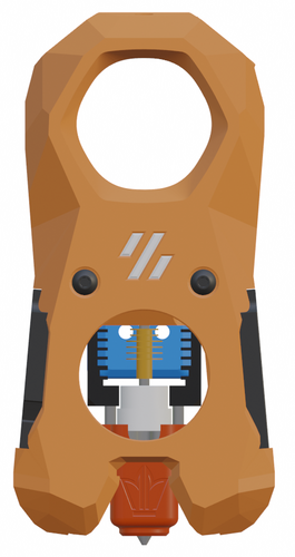
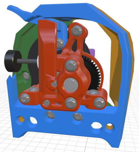
atrushing 994 Posted February 23, 2023 Share 15 hours ago, nooss said: is there any possibility to make it compatible with Voron tap ? While it is mechanically feasible to adapt the Voron TAP front piece to fit the Mini Stealth, there are a few issues that arise. The red represents the part of the TAP that would need to be removed to make space for the 4010 blowers. This means that the timing belt loops would need to be removed or re-designed. It also means that new support structures would be needed to make the new overhangs printable. The orange area is the mating face of the shroud. This area is sufficiently rigid for standard printing but with 600 grams of TAPping force I am afraid that it would not be enough. To manage this, the shroud would need a feature added at the bottom to hook onto the two BHCS. This is a very tight area because it is the back of the cooling ducts. I believe the worst part of this mashup is that the airflow of the hotend cooling fan would have nowhere to exit and would lead to unmanageable heat creep. The only remotely plausible solution I can imagine would be to flip the part cooling fans around so they can pull dirty air away from the hotend. This would of course introduce several other problems.. A final concern is that the top piece (grey) which holds the sensor PCB might interfere with the extruder and stepper motor and that wire routing might get very tight. 1 Quote Link to comment Share on other sites More sharing options...
mvdveer 2,773 Posted February 23, 2023 Share 6 minutes ago, atrushing said: A final concern is that the top piece (grey) which holds the sensor PCB might interfere with the extruder and stepper motor and that wire routing might get very tight. Just sounds too much to overcome at this moment. Whilst it would be nice, there are alternatives that may work just as well. But then you are a pioneer and if this can be achieved, I am sure it will be grabbed by many. 1 Quote Link to comment Share on other sites More sharing options...
kde 4 Posted February 23, 2023 Share 26 minutes ago, atrushing said: While it is mechanically feasible to adapt the Voron TAP front piece to fit the Mini Stealth, there are a few issues that arise. The red represents the part of the TAP that would need to be removed to make space for the 4010 blowers. This means that the timing belt loops would need to be removed or re-designed. It also means that new support structures would be needed to make the new overhangs printable. The orange area is the mating face of the shroud. This area is sufficiently rigid for standard printing but with 600 grams of TAPping force I am afraid that it would not be enough. To manage this, the shroud would need a feature added at the bottom to hook onto the two BHCS. This is a very tight area because it is the back of the cooling ducts. I believe the worst part of this mashup is that the airflow of the hotend cooling fan would have nowhere to exit and would lead to unmanageable heat creep. The only remotely plausible solution I can imagine would be to flip the part cooling fans around so they can pull dirty air away from the hotend. This would of course introduce several other problems.. A final concern is that the top piece (grey) which holds the sensor PCB might interfere with the extruder and stepper motor and that wire routing might get very tight. Instead of removing, I would install an adapter Quote Link to comment Share on other sites More sharing options...
atrushing 994 Posted February 23, 2023 Share 13 minutes ago, mvdveer said: Just sounds too much to overcome at this moment. Whilst it would be nice, there are alternatives that may work just as well. But then you are a pioneer and if this can be achieved, I am sure it will be grabbed by many. It is really too bad, I was hoping it could work. If there was a solution to the hotend cooling, the other issues could most likely be designed around. 1 Quote Link to comment Share on other sites More sharing options...
atrushing 994 Posted February 23, 2023 Share Just now, kde said: Instead of removing, I would install an adapter Any adapter would need to be at least 5mm thick. It would need to be even thicker to add room to allow the hotend cooling to get past the 4010 blowers. This thickness would directly translate to extra Y axis offset and the TAP already moves the nozzle 3mm forwards. Moving the toolhead forward also reduces rigidity and the TAPping forces would be amplified. The compact nature of the Mini Stealth is both a blessing and a curse.. Quote Link to comment Share on other sites More sharing options...
Buurman 891 Posted February 23, 2023 Share With what is said, I do think a TAP version is a bridge too far.. maybe if the design of the tap wasnt so bulky it was possible but yes, it a thick and heavy addition where I think the "rush" SB Mini is mostly about loss of weight, having a lighter print head. I do think adapter like thinking, but then just for a more rigid connection to the X carriage, like mentioned before. I cant design it, but I will try to think of an possible option there. The piece that connects to the X carriage is too small, the part taken out for wiring, doesnt make it better. Also, instead of 2 screw connection, I hope a 3 or 4 screw is possible, again... I hope I can help in brainstorming on this. Dont get me wrong, love what you are doing, its a incredible amount of adjustments needed on what I am suggesting, so I understand thats not something to look forward to but I mean well. 1 Quote Link to comment Share on other sites More sharing options...
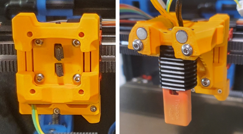
atrushing 994 Posted February 23, 2023 Share 40 minutes ago, Buurman said: Also, instead of 2 screw connection, I hope a 3 or 4 screw is possible, again... I hope I can help in brainstorming on this. There are very few ways of accomplishing this. One would be to raise the extruder so that there would be more room for another screw or two. This would have a side effect of making it harder to fit the extruder into the shroud, something that is already a bit tricky with certain extruders. On the V2.4/Trident I could possibly sneak screws at the bottom but this wouldn't help the V0.1/V0.2 and the screws would be awkward to reach. I don't want to rely on a solution that would only work for certain hotends. A lot of the work I have put into this has been to make the design hotend and extruder device-agnostic. I think that a simple thing to maximize rigidity with the current design would be to use quality stainless steel screws which are stronger than galvanized or coated screws. The strength of steel is easy to underestimate. The plastic is only under compression. The shroud could be printed at a higher infill as it only weighs 30 grams with 40% infill. I have re-worked the geometry for all of the shrouds and each x_carriage version to apply the improvement shown in the next two pictures. The head of the screw pushed against a chamfered face and the heat-set insert was installed from the front of the carriage. Both of these issues have been improved. The screws just need to be 5mm longer to fit this change. Now I just need to find time to export all of the new files and upload them.. Quote Link to comment Share on other sites More sharing options...
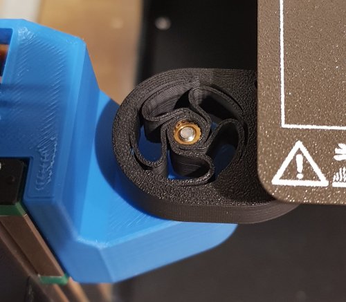
Buurman 891 Posted February 23, 2023 Share I think this may already help a lot, never noticed this, the heat insert from back is also added? I was also looking of cables could go trough a hole over the fan, instead of "over" the duct. But this seems impossible for the Revo, and possibly other hotends too, since bending the cables close to the thermistors is often impossible to make that corner. EDIT: adding some ideas.. 1. maybe a small hole in the suggested corner could be good to put fan cables trough, and make the (quite large) gap on top less than half its size. It can easily be half with a revo, but having some cables go through the back, makes it even easier. if made half its width, add plastic close to the mount hole for strength, create the gap close to the middle as possible. 2. For the Revo one, the shape where it mounts can (maybe should) be different, its not round, and would be good in ways of strength and space for a cable hole, but mostly strength. 3. the cable of the left fan, it may be better to have it join the other cables instead of having its own cutout, again, strength. Also this would take away the nasty cable bend from the fan, as you can see, this, with some bad luck can damage your fan.. Quote Link to comment Share on other sites More sharing options...
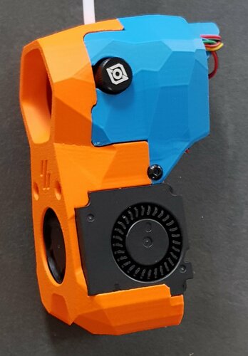
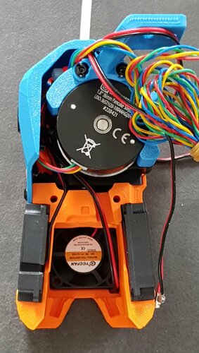
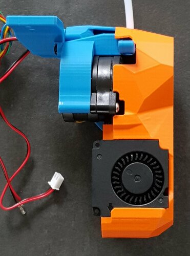
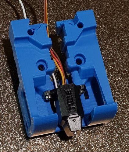
Buurman 891 Posted February 23, 2023 Share Ideas on the X-carriage (V2.4) .... 1. it has minimum touch to the front, again, the gap for cables is too wide, and could bring more stability made narrower, closer to the middle if possible. With use of the X-carriage, the whole gap isnt needed, the X-carriage provides a large gap? (second photo) 2. I would be perfectly fine in cutting off the ear of the fan for stability, and it seems like there is lots to win there. The X-carriage woudnt need the narrowing exactly at its mount holes. 3th photo 3. for me (could be print, but normally my prints are at scale, I noticed I cant close the X-carriage up to the front, it closes on the side fans, but not on print... there is a 0.2mm gap or so.. (could be my brand of fans, but it cant fit right like this). 4. the bottom part I dont get, it doesnt fit over both of two fan ears, it always slips on one side. Again, take of the ears of the fans and a more sturdy connection is possible, maybe even screws? Quote Link to comment Share on other sites More sharing options...
atrushing 994 Posted February 23, 2023 Share 1 hour ago, Buurman said: the heat insert from back is also added? Yes, I moved the insert to the back of the x-carriage. When trying to add strength to the system, it is only as strong as the weakest part. The area with the green rectangle is in compression and the screw creates the strength. Unless this material is getting crushed when installed, there is little that could be done to add strength here. Increasing the mating faces at the cyan rectangles could help counter the bending moment caused when applying force at the nozzle. The magenta oval is the weakest area and the layers are not going in the best direction (but this would be very hard to change). The Orbiter extruders are the worst at this area because the stepper motor sits so low while the Mini Sherpa allows the best cross sectional area here. I hope I don't need to add the screwdriver in this illustration 2 1 Quote Link to comment Share on other sites More sharing options...
Buurman 891 Posted February 23, 2023 Share 1 hour ago, atrushing said: I hope I don't need to add the screwdriver in this illustration Whaaaat? Should we guess??? 2 Quote Link to comment Share on other sites More sharing options...
atrushing 994 Posted February 23, 2023 (edited) Share 4 hours ago, Buurman said: 1. maybe a small hole in the suggested corner could be good to put fan cables trough, and make the (quite large) gap on top less than half its size. It can easily be half with a revo, but having some cables go through the back, makes it even easier. Having an extra place for some of the wires to go would be nice but with different extruders above the different hotends it would be very hard to find a safe place to have the wires come out through the top. I want to keep the design as universal as possible. If the strength and the routing for a Revo with a LGX Lite is different than a Revo with a Mini Sherpa then the design starts branching too much and gets very difficult to maintain. I think that the change I am trying to push right now will make a good difference. Also, I think you will be pleasantly surprised with the Mini Sherpa and the x-frame pieces. 3 hours ago, Buurman said: 3. for me (could be print, but normally my prints are at scale, I noticed I cant close the X-carriage up to the front, it closes on the side fans, but not on print... there is a 0.2mm gap or so.. (could be my brand of fans, but it cant fit right like this). 4. the bottom part I dont get, it doesnt fit over both of two fan ears, it always slips on one side. Again, take of the ears of the fans and a more sturdy connection is possible, maybe even screws? I've only had to print these parts once and it worked well enough since I designed it around the fans that I have.. I really should make a little more room for fans from different suppliers. Adding screws at the bottom would help with rigidity but then I would need to maintain 28 more shroud versions. This brings to mind wise words from @Penatr8tor, 'is better the enemy of good enough?' The V2.4/Trident x-frame will be more rigid than any of the V0.1/V0.2 x-carriage pieces. Is it necessary that the Mini Stealth is as rigid as the full size Stealthburner? Edited February 23, 2023 by atrushing 3 Quote Link to comment Share on other sites More sharing options...
atrushing 994 Posted February 23, 2023 Share 3 hours ago, Buurman said: Here is the new version with an extra 0.5mm in the back and at the bottom of the blowers. x_frame_Mini_Stealth_left_v1.2.2.stl x_frame_Mini_Stealth_right_v1.2.2.stl Quote Link to comment Share on other sites More sharing options...
Penatr8tor 2,025 Posted February 23, 2023 Share Ahhhh... so this is where you've been hiding. Mini Stealth with TAP. Cool. I'll be watching. 1 Quote Link to comment Share on other sites More sharing options...
Recommended Comments
Join the conversation
You can post now and register later. If you have an account, sign in now to post with your account.