Search the Community
Showing results for tags 'richardjm'.
Found 5 results
-

Version 2021.12.07
4,726 downloads
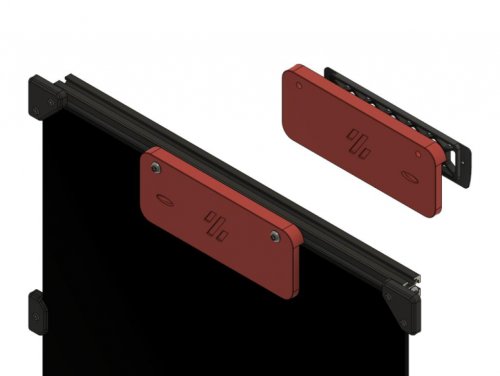
Printable quick release latch for panels on 2020 extrusion This is originally inspired by a youtube video - https://www.youtube.com/watch?v=6p7M18oPn3k Another user is creating cad and variants - https://github.com/v6cl/My-Voron2.4-Customs/tree/main/Panel_Locker So why did you do it? I wanted a variant with filament hinges I found it didn't put quite enough pressure on the panel and my attempts to moodify the cad failed Decided the best way to understand it was to design it Wanted adjustable -
Version 2021.09.14
274 downloads
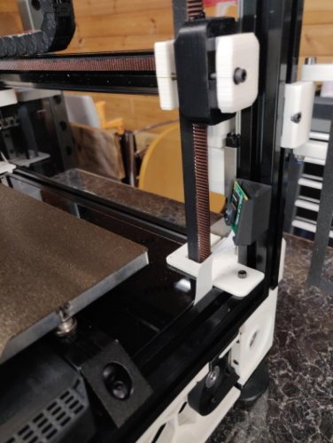
Picam corner mount About the only place I found to mount the picam with a view low down of the bed. This was inspired by the v0 design by xbst Hardware A single m3x8 bolt and t-nut A suitable length of picam ribbon cable -
Version 2021.10.03
154 downloads
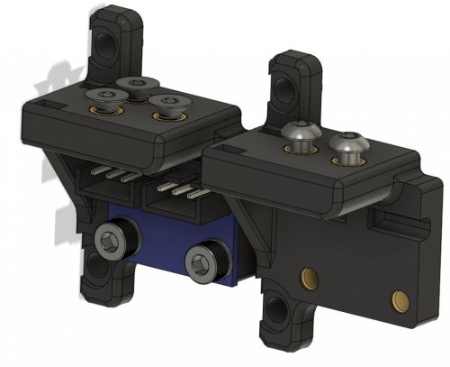
ADXL345 GY-291/Adafruit Cable chain anchor mount WARNING: Dupont connectors can foul with your z-chain when homing, solder wires directly or ensure you have clearance. This is a mod for mounting the ADXL permanently. It moves your drag chain up by 5.5mm on the motor. From testing this mount eliminates the Z component when measuring the Y resonance. Check for clearance at the limits of movement Clearance cad check for Adafruit board. Hardware DO NOT USE dupont on the ADXL boards, ensure you have clearance when homing using JST XH connectors or solder wires directly ADXL345 GY-291 board (21mm by 16mm) ADXL345 GY-291 board (21mm by 16mm) M3x6 BHCS M3 nylon/Printed washer (optional) M3 Threaded Insert * 3 or 5 (IGUS or Generic) Adafruit ADXL345 board (1in by 0.8in) Adafruit ADXL345 board (1in by 0.8in) M2.5x6 BHCS (threads into plastic) M2.5 nylon/printed washer (optional) M3 Threaded Insert * 2 or 3 (IGUS or Generic) Ideas that didn't work Dupont connectors on the ADXL board are too tall and foul the drag chain when homing. Attempting to use the three motor mounts doesn't work. Using the top hole would interfere with the drag chain as it's closer to the motor than the bolt. Using the bottom hole fouls the drag chain when X approaches 0. Using M3x8 bolts on the board moves the board closer to the back risking fouling with JST-XH connectors - would probably be ok if soldering wires directly. Attempting to not move the drag chain mounting up the motor doesn't give clearance as X approaches 0 for the board, it's too close to the bottom of the motor. Flipping the drag chain mount so it's level with the top of the motor instead of moving it up just makes the radius of the drag chain tighter and more awkward to fit. Trying to use threaded inserts for the Adafruit board would make the edges too thin -
Version 2021.10.08
766 downloads
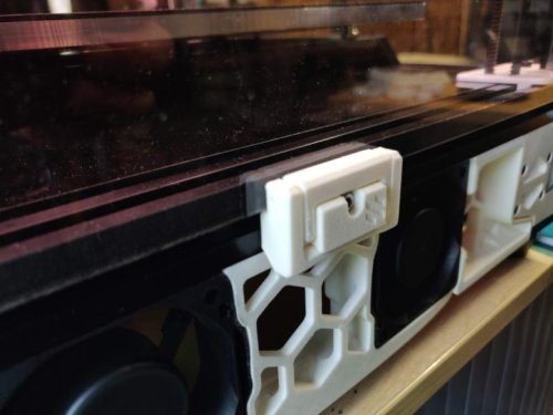
Back plate blanking plate If you choose not to use the exhaust - perhaps you're planning on fitting a nevermore instead. This is a blanking plate with integrated bowden tube route that goes in place of the exhaust filter housing. It makes use of the existing grill with one strut removed (use the stl here or cut out a strut of a grill you already have printed) as I liked the look of it. Instructions Choose the appropriate blanking plate, the depth should be that of your back plate including the foam (distance from the flat of the extrusion to the flat of the back plate) Put foam on the edges of the blanking plate that contact the back plate and extrusion Cut out a strut from the exhaust grill or print a new one 2 x M5x16 (for the 5mm variant) 2 x heatset inserts into blanking plate Existing M5 T-Nut and M3x12 bolt from exhaust filter housing Ream the bowden path and push the tube through, it is a tight fit Thread the tube through the grill before attaching to your extruder, not that I would have done that, oh no Tighten it all into place Installed Ignore the missing m3 screws holding the grill in place, it's because the led bar interferes. -
Version 2021.09.26
166 downloads
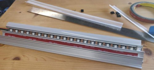
Quarter round led mount with integrated cable run An integrated led mount that sneaks the cables behind the z idlers. This part is all you need to hold the led string in place and hide away those cables. Hardware A single m3x25 bolt, m3 washer and t-nut JST-XH 3 way connectors and short cable runs from end to end (whatever connectors suits your LED strips best) LED strip - I used neopixels but you can use whatever 15.5mm quarter round LED extrusion with diffiser VHB tape if necessary Mounting To get the data and power I ran a cable up from the electronics bay in the rear extrusion. To hold the cable in place up the extrusion I used kapton tape as I thought using cable clips could interfere with the gantry motion. Fit LED strips into extrusion with VHB tape if required, having a short length of cable on one end sufficient to reach through the corner mount to the next led strip in the chain, the input end can be a JST-XH connector soldered directly to the strip I found. Do what works for your LED string. Start at one corner putting the connector from the electronics bay where it's needed and fasten a corner or end into the extrusion using the m3x25, t-nut and washer. Put the other corner up and run the cable through, putting the bolt in after making sure not to crush it. Attach to the next strip and put the strip in the corner mount before fitting the second bolt. This allows the cable more space to fold into the mount. Fit the bolt while holding the extrusion up and continue around the printer fitting as many corners or ends as you need.