-
TeamFDM.com is an UNOFFICIAL companion site for the DIY Voron 3D printer community. For official docs and final source of truth, visit the Official Voron Discord or the Voron Github
Printable Voron User Mods
Voron User Mods, or "UserMods", are a collection of community created and Team FDM curated modification for Voron Printers. All of these mods are available on the VoronUsers Github repo and unless otherwise specified follow the Voron communities GPL3.0 Licensing. Use any Mods at your own risk, if you make modification please share them on the VoronUsers repo.
Mod Authors: Have a Voron mod? Upload it at TeamFDM.com and let us know you're the author. We will ensure you can update and curate your files for more feedback! Please include tags for what Voron, or extruder your mod is compatible with.
660 files
-

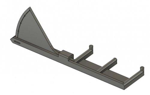
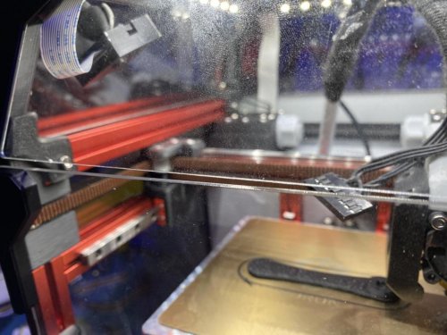
Tension Meter
README
Overview
Inspired by the print in place tension meter Prusa released recently, I drew up this one from scratch.
It's not intended to give you an absolute result but I found it accurate enough to measure the same tension independent off the orientation you mount it with. Therefore it should be accurate enough to set multiple belts to the same tension (e.g. V2 z-belts).
Print instructions:
Only tested with KVP ABS.
Always print it with 100% infill
Application:
The meter has three
214 downloads
(0 reviews)0 comments
Submitted
-
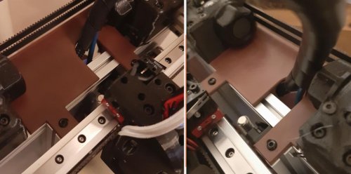
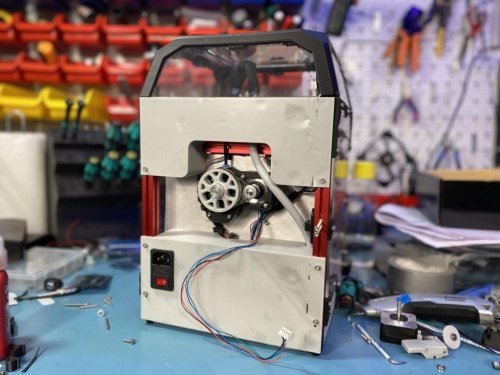
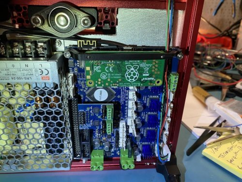
Electronics Bay Seperator
Electronics Bay and Chamber seperator.
A plate to seperate the enclosure, from the electronics compartment. The chief advantage in using this part, is it allows you to drastically reducde the size of the back panel, while maintaining chamber temperature. This wouuld allow you to run a larger extruder if desired. It also will help to keep the Raspberry Pi running cooler, and even for active cooling for the electronics or stepper motors should you deem it necessary.
I aimed to create something easy to install on a machine already built. Also easy to remove for maintenance or modifcation. Prints in 1 piece on the V0 bed.
0 downloads
(0 reviews)0 comments
Submitted
-
Jetpack V0
Purpose: Attaching Jetpack to V0
Why: Base needed to be adjusted to 1515
What else: From Voron with love!
5 downloads
(0 reviews)0 comments
Submitted
-
V0 TR Mounting Frame
Purpose: attaching TacoRaven Board to the backside of a V0
Why: Because you need it if you a Taco lover.
What else: From Voron with love!
0 downloads
(0 reviews)0 comments
Submitted
-
DIN Rail 2020 Holder
Purpose: attaching DIN RAIL with 25mm inner width to 2020 rails
Why: You can avoid attaching DIN rails to the bed and easily move/adjust them - specially on smaller ones.
What else: From Voron with love!
21 downloads
(0 reviews)0 comments
Submitted
-
Single Panel Magnet Mount
Voron 2.4 Front Magnet Panel Mounting System
Mounting system for attaching a panel to the Voron 2.4 frame using magnets, primarily intended for the front panel.
BOM:
Magnets (quantity 64 (get a few spares), ~$25): https://www.kjmagnetics.com/proddetail.asp?prod=B442 Heat set inserts (quantity 24, ~$19): https://smile.amazon.com/gp/product/B077CJV3Z9 M3 T-nuts (quantity 24 ~$12), with a centered threaded hole, I used the type I could roll into the frame:60 downloads
(0 reviews)0 comments
Submitted
-
DIN Rail SKR 1.3 90deg
Purpose: Turning SKR V1.3 90 degrees on a DIN rail. Standard base is used.
Why: To optimize space/electronics arrangement.
What else: From Voron with love!
1 download
(0 reviews)0 comments
Submitted
-
(0 reviews)
0 comments
Submitted
-
V0 M4 Mod
# M4 Mod For V0 This mod lets you mount a Mobius 4 on a Voron 0.
This mod will interfere with the rear panel if you use the printed 80T idler. Alternatives are either using the Powge Voron 80T pulley, or using my no rear panel mod.
I wrote a manual for assembly. You can find that here.
Printed Parts Needed in M4 Files
You need both .stl files included in the mod folder, also you need:
main_body_mirror.stl latch_shuttle.stl [a]_latch.stl [a]_guidler_mirror.stl [a]_5x4mm_spacer.stl Confirmed Motors That Work
I will edit this list if more motors are confirmed working.
E3D Slimline Motor Confirmed Motors That Don't Work
Tevo Titan Pancake Motor LDO High Temp 0.9 Motor LDO-42STH25-1404MAH6 downloads
(0 reviews)0 comments
Submitted
-
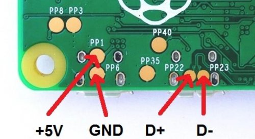
DuetZero
# DuetZero Duet2 Pi Zero Mount This is a Raspberry Pi Zero mount intended to mount OVER a Duet 2 (DuetWifi/Ethernet) to save space. You only need longer M3 screws for Duet mounting and M2 self tappers for Pi mounting.
First mount the Zero on the piece, preferably inside as that is what is intended. Use 2 M2 self tappers for this. If the screws poke out on the other side cut the ends to prevent accidents. Then using M3 screws mount this to USB side of the Duet.
This mount is intended for a Voron 0 but should work with any other Vorons.
1 download
(0 reviews)0 comments
Submitted
-
V0 Screw Front Hinge Mod
This mod is to allow you to screw the front door panel (instead of VHB).
You need 6x 6mm M3 screws and 6x M3 inserts.
Designed for 3mm panels but should work with thinner panels as well, just use foam tape if the gap is too big.
Insert the M3 inserts to the handle and corner pieces.
Included drilling guides will let you drill the holes accurately. I recommend using 4mm (or whatever
32 downloads
(0 reviews)0 comments
Submitted
-
(0 reviews)
0 comments
Submitted
-
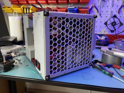
V2.4 Fanless Middle Skirt
A replacement middle skirt that doesn't protrude below the bottom plate, and has no fan mounts.
35 downloads
(0 reviews)0 comments
Submitted
-
V0 Picam
V0 Raspberry Pi Camera Mount
Attaches to the corner bracket of the top hat using a longer M3 screw. Camera mount taken from: https://www.thingiverse.com/thing:3017729
15 downloads
(0 reviews)0 comments
Submitted
-
Flat Skirts
# Flat V2.4 Skirts This is to mount a flat bottom panel without cutouts. Includes rear filtered inlet and side middle skirts. No front skirt as that is on a hinge anyway. Inlet skirt uses M3 inserts.
8 downloads
(0 reviews)0 comments
Submitted
-
(0 reviews)
0 comments
Submitted
-
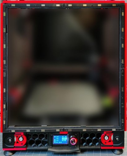
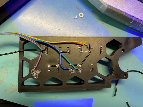
V2.4 Skirt Buttons
Voron V2.4 Skirt Buttons Mod
Switches Needed
Printer Size Qty Needed 350 12 300 8 250 4 You need 12*12mm 5mm tactile switches. Make sure they are through hole, not SMD! Here are a few examples: Amazon: https://amzn.to/3788dfZ Aliexpress: https://s.click.aliexpress.com/e/_eKCJlo
Wiring
Put the switches in the hexagons, bend the legs of the switches. Wire one side of the switches together, connect to the mcu or Pi (depending on your config). Connect seperate wires to the opposite sides. I recommend using hot glue to keep the wires in place. Otherwise you may disconnect the solder joints, or worse, break the legs of the switches when installing by accident.
Gluing The Buttons
I recommend using hot glue for attaching the printed button caps to the switches. You can also use super glue, but you may need to space the caps by putting a washer in between as hot glue is thicker.
You may need to cut the elephant foot if the buttons get stuck when pressed.
Config Options
You have 2 choices: Using FW of your 3D printer (like Klipper), or using Octoprint's Enclosure plugin.
Config for Klipper
Here is the relevant config info from GitHub page of Klipper.
# Execute gcode when a button is pressed or released (or when a pin # changes state). You can check the state of the button by using # QUERY_BUTTON button=my_gcode_button #[gcode_button my_gcode_button] #pin: # The pin on which the button is connected. This parameter must be # provided. #press_gcode: # A list of G-Code commands to execute when the button is pressed. # G-Code templates are supported. This parameter must be provided. #release_gcode: # A list of G-Code commands to execute when the button is released. # G-Code templates are supported. The default is to not run any # commands on a button release. Config for Octoprint
Install the plugin768 downloads
-
(0 reviews)
0 comments
Submitted
-
Omron DIN Mount
This is for mounting the stock Omron Relay to the DIN rails without buying the Omron mount. You will also need the
14 downloads
(0 reviews)0 comments
Submitted
-
Max31865 DIN Mount
This is for mounting a Adafruit MAX31865 board (and SAME SIZE clone) to the DIN rails. You will also need the
0 downloads
(0 reviews)0 comments
Submitted
-
Relay DIN Mount
This is for mounting a Raspberry Pi 4 Relay Module to the DIN rails. You will also need the
8 downloads
(0 reviews)0 comments
Submitted
-
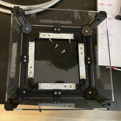
Hat LED Mount
This mounts to the top hat. You need to print 4x of them. Fits on a v0 bed with creative angles.
LED Module Example (TR only, try to find similar): https://www.iled.com/urun/3000k-2835-smd-samsung-led-bar-ic-mekan-35-led-24v-50cm
0 downloads
(0 reviews)0 comments
Submitted
-
HOYMK SSR Mount
# HOYMK SSR Mount This is to mount a Chinese HOYMK SSR to a Voron 0. Please don't use this on a larger build! This is a Chinese product, it may not handle power needs of larger builds even if they claim that it does.
3 downloads
(0 reviews)0 comments
Submitted
-
LED Holder
This mount is for some 50 cm PCB LEDs I found online. I have no idea if this is a common form factor or not but it is available on at least 3 stores here so I think it is.
I am using this 24V Samsung module for this purpose. [Link (in Turkish, but you can use for comparing): https://www.iled.com/urun/3000k-2835-smd-samsung-led-bar-ic-mekan-35-led-24v-50cm ]
You can cut these every 10cm, so the .stl is for just for that size. Just use multiple mounts for longer than 10cm.
Print these in ABS, PLA warps with heat of the chamber.
On a 350 voron 2.2 on the top extrusions you can mount 14 modules at once. Reduce as you go smaller.
You will need 1 m3 screw and 1 m3 nut, along with 2 m5 screws and tnuts per module (use both holes, otherwise it may warp).
4 downloads
(0 reviews)0 comments
Submitted
-
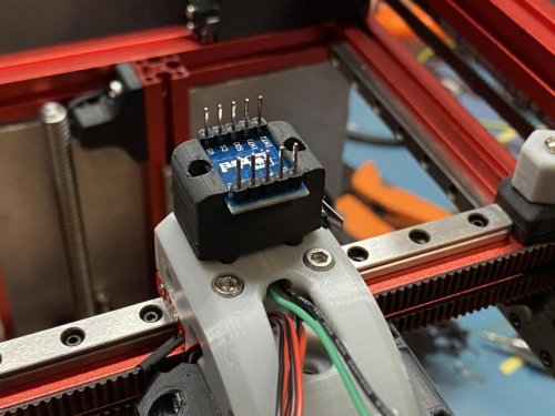
ADXL345 V0 Mount
This works for this type of ADXL345 modules: https://s.click.aliexpress.com/e/_dUndeBj
Fits snugly into the 3 M2 screw holes for the X carriage. Module just slides in from the side. Attach the 2 pieces with M2 self tappers.
2 downloads
(0 reviews)0 comments
Submitted