-
TeamFDM.com is an UNOFFICIAL companion site for the DIY Voron 3D printer community. For official docs and final source of truth, visit the Official Voron Discord or the Voron Github
Printable Voron User Mods
Voron User Mods, or "UserMods", are a collection of community created and Team FDM curated modification for Voron Printers. All of these mods are available on the VoronUsers Github repo and unless otherwise specified follow the Voron communities GPL3.0 Licensing. Use any Mods at your own risk, if you make modification please share them on the VoronUsers repo.
Mod Authors: Have a Voron mod? Upload it at TeamFDM.com and let us know you're the author. We will ensure you can update and curate your files for more feedback! Please include tags for what Voron, or extruder your mod is compatible with.
660 files
-

V0 Deck Logo LED
V0 Illuminated Deck Logo
A lower deck panel addition to the V0, designed to accomodate a Neopixel Ring.
Print
Deck_Logo_Insert_Transparent
Printed with a clear filament to allow for the glow that is represented in the pictures. Recommend50 downloads
(0 reviews)0 comments
Submitted
-
V0 LED Front Bed Mount
V0 LED Front Bed Mount
This modification was designed to accomodate a Neopixel Jewel (7) in the face of the mount. Wiring is ran to the cable chain and ultimately to an Arduino Nano as a controller.
The file
27 downloads
(0 reviews)0 comments
Submitted
-
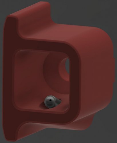
V0 C14 Inlet Foot
V0 C14 Inlet
A simple modification to the rear foot of the V0 to allow for the addition of a C14 Inlet.
Note - this is not compatible with the rear, lower deck panel that sits below the Z Mount.
2 downloads
(0 reviews)0 comments
Submitted
-
Extrusion Backers
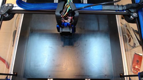
Gantry Backing Plates
The theory
Due to different thermal coefficients of linear expansion between steel (rails) and aluminum (extrusions), the Voron V2 gantry forms a sort of giant bimetal temperature sensor element. This causes a warping of the gantry as it heats up with increasing chamber temperature.
The evidence
While exploring frame expansion behavior, a number of us were noticing empirical values several times what we'd predict simply due to linear expansion of the Z extrusions alone. Although plugging those empirical values in to the compensation code has given me great first layers, the difference from expectation was still bothering me. Maybe, I thought, there was some sort of warping happening? Checking out a table of thermal expansion coefficients, I saw that indeed aluminum expands quite a bit more than steel with temperature.
Bottom X rail increases frame thermal compensation value
After some discussion on Discord, it appeared that people running the BOM double X rail, with an MGN9 rail on the front and bottom of the X extrusion, by and large seemed to be needing higher compensation values than those who only had a single X rail on the front face of the extrusion.
So I tried loosening the screws on the bottom X rail of my V2.4 350, and re-ran the thermal expansion measurment. Wouldn't you know it, my observed compensation factor went from around 2.8 to about 1.5:
Bed mesh changes as predicted with frame temperature
To confirm, I decided to go ahead an loosen all the rails on both X and Y, heat soak the machine for a couple hours, and then tighten them down; this should ensure that the gantry is as flat as possible when at temperature, but will bow downwards when it is cold as the aluminum contracts more than the steel rail beneath.
And that's indeed what I saw. After hot-tightening the rails, I took a bed mesh while everything was still hot. I then allowed the printer to cool for a couple hours, reheated the bed, and took another mesh while the bed was hot but the frame was still cold.
What I saw was just what we'd predict, with the
50 downloads
(0 reviews)0 comments
Submitted
-
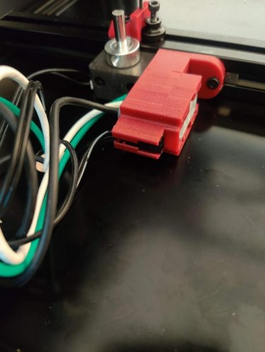
Crydom GN Guard
Crydom GN series terminal guard
I replaced the SSR on my build with a Crydom GN series SSR. The model I received didn't have the terminal cover, so I created a simple cover that is secured with the mounting screw on the SSR, and helps prevent accidental touching of the high voltage terminals.
Installed it looks like this:
Printed in eSun ABS with standard Voron print settings.
7 downloads
(0 reviews)0 comments
Submitted
-
Voron2.4 Cable Clamps
Cable clamps
I used this set of clamps to route and secure the wiring in my Voron 2.4 350mm.
There are three types, each requiring an m3 bolt and t-nut in order to secure them to the inside perimeter of the upper (meaning closest to the deck) 2020 extrusion. The deck should rest on top of the clamps. You'll likely need a ball-end hex driver in order to connect to the nut at an angle via the access hole.
Each type of clamp has an internal channel for multiple small zipties, and the DIN rail clamps also provide secondary holes along the rails.
openscad files are provided for your own tinkering needs.
Clamp types
The first type only secures along the perimeter. I used this to secure high voltage wiring from the power inlet to the power supplies. Multi
77 downloads
(0 reviews)0 comments
Submitted
-
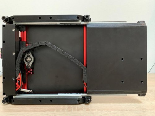
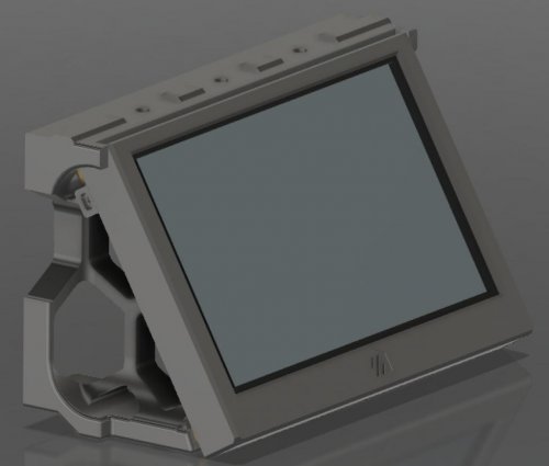
Drawer
Drawer in four different versions
you have to drill a 4mm hole yourself on the drawer rail (s. image)
Required material:
Cable Chain with 15 chain links:
90 downloads
(0 reviews)0 comments
Submitted
-
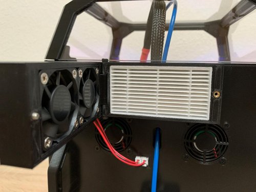
HEPA Filter
HEPA filter with easy access to change the filter
Carefully drill the 1mm hole to 3mm for the hinge (fan case) Carefully drill the 1mm hole to 2.5mm and cut an M3 thread into it
Required material:
Filter: https://www.aliexpress.com/item/32788652288.html
Carbon Pad: https://www.amazon.com/EA-Premium-Carbon-Infused-Filter/dp/B07T3PPH4C
9x M3x4mm heat inserts
8x M3x16 countersunk flat head for the fans
1x M3x10 countersunk flat head as door lock
2x M3x20 BHCS as hinge
33 downloads
(0 reviews)0 comments
Submitted
-
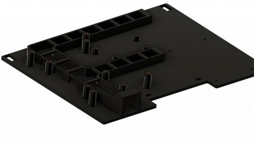
Mid Panel
Mid-panel for SKR1.3/1.4 or SKR E3 mini. Once with and once without cable management
Required material:
4x M3x4mm heat inserts for DC/DC Converter
4x M3x6 BHCS
4x M3x4mm heat inserts for SKR1.3/1.4 boards
4x M3x6 BHCS
or
5x M3x4mm heat inserts for SKR E3 mini
5x M3x6 BHCS
15 downloads
(0 reviews)0 comments
Submitted
-
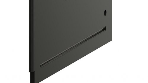
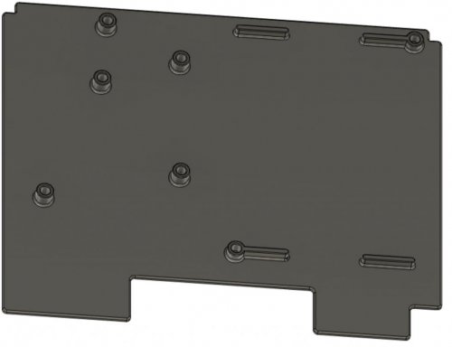
Deck Panel Rear
Deck Panel to cover the hotbed cables
Required material:
6x M3x8 countersunk flat head
4 downloads
(0 reviews)0 comments
Submitted
-
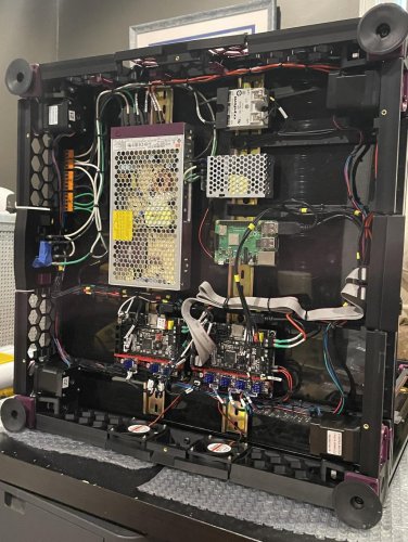
Back Door
Door for easy access to electronics
Carefully drill the 1mm hole to 3mm for the hinge
Required material:
2x M3x30 BHCS as hinge
4x M3x6 BHCS for PCB
6x M3x8 countersunk flat head for filter and handle mounting
2x Magnets 6x3mm
10x M3x4mm heat inserts for handle and fan mounting
54 downloads
(0 reviews)0 comments
Submitted
-
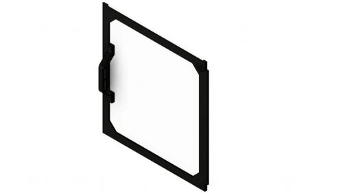
Front Door
Front door frame
Carefully drill the 1mm hole to 3mm for the hinge
Required material:
4x M3x8 countersunk flat head for the handle
2x Magnets 6x3mm for the handle
13 downloads
(0 reviews)0 comments
Submitted
-
Neopixel Y Rails
Mounting of neopixels on the Y-rails
Required material:
5x M3x4mm heat inserts
2x M3x6 BHCS for Neopixel
3x M3x6 countersunk flat head for cover
2x M3x8 BHCS for mounting on Y-rails extrusion
8 downloads
(0 reviews)0 comments
Submitted
-
6mm Glass
Glass mount
This is a modification of the front panel locks from 2.1 to support holding 6mm tempered glass panels. I used 3m VHB to adhere them to my glass panels so that thickness was considered as well. The tab which supports the glass was thickened and has proven to be very robust on my printer. This can be run with 2.4 without issue, using panel sizes from the 2.1 bom.
I've also added 'Glass_Rest.stl'
48 downloads
(0 reviews)0 comments
Submitted
-
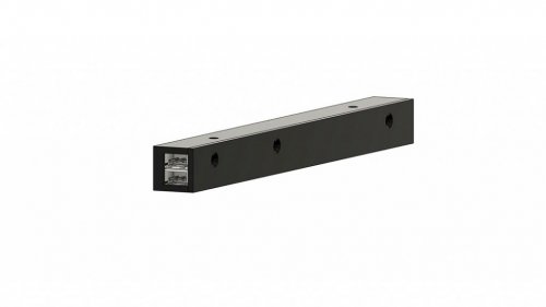
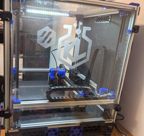
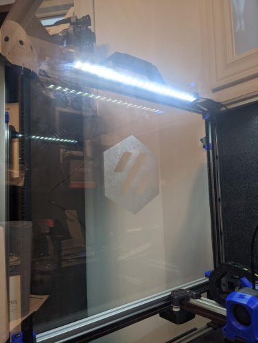
LED Mounts
LED Mounts
This is a simple LED light bar mount for this 12V LED Strip light: https://www.banggood.com/30CM-8W-SMD5630-Waterproof-U-Shape-Dual-Row-42LEDs-Rigid-Strip-Hard-Bar-Light-DC12V-p-1255036.html
I run this off a 12V power supply, and groundside switch it on an SKR: https://www.digikey.ca/en/products/detail/cui-inc/VGS-25-12/2045660
You will need 1 A
12 downloads
(0 reviews)0 comments
Submitted
-
C920 Mount
C920 Mount
This is a mount for a Logitech C920 webcam for the front top extrusion on the Voron 2. On my 350 the field of view looks like this: .
This is how it looks mounted in the printer:
I used to M3x10 SHCS to attach to my extrusion with a couple t-nuts.
This is a video of the Disassembly which you will need to perform in order to use this bracket. Disassemble until you can get the two metal swivel joints undone, slide into the two holes on the mount, then reassemble.
122 downloads
-
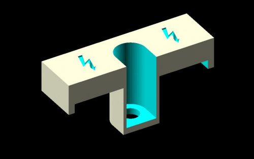
Z Chain Guide Thermistor Mount
Voron V2.4 Z Chain Guide with Integrated Thermistor Mount
When looking for a clean way to mount a chamber temperature sensor, the Z chain guide seemed like a perfect opportunity. It should fit any thermistor with a 3mm barrel.
Installation
Route your wire through the Z chain to the rear X extrusion Secure the wire inside that extrusion Insert the thermistor into the mount Attach the mount to the extrusion, positioned to hold the Z chain vertical* **NOTE: Ensure you have enough links in your Z chain to clear the guide when at max Z.*
297 downloads
-
(0 reviews)
0 comments
Submitted
-
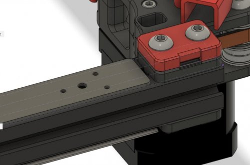
Molex MLX Microfit Bed Connector Mount
Molex MLX and Microfit Bed Connector Mount
This part provides a solid mount for the 3 circuit MLX receptacle and a 2 circuit Micro-Fit 3.0 plug housing from the v2.4 BOM. I recommend you put these connectors on the electronics side. Mounting the connectors this way allows you to more easily hide the wires and disconnect the bed from the printer with one hand after lifting the bed. It can be mounted on either bed extrusion, and in either Y orientation you prefer. Example orientations are shown in the images.
Parts Required
Part Quantity Comment M3 X 8 SHCS 2 M3 T-Nut 2 Printing
Print using standard Voron part settings and in the orientation used in the STL Installation
The MLX connector should snap in smoothly It must be inserted from the flat side of the mount and only in 1 orientation Orient the alignment flange closer to the screw-side of the mount The Micro-Fit 3.0 will be a little more difficult to insert. Apply pressure until it snaps into place Both will come back out without destroying the connectors or mount, but it takes some finesse49 downloads
-
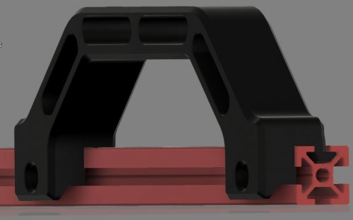
Sturdy Handles
Voron v2.4 Sturdy Handles
I wanted handles for the v2.4 that were a bit more sturdy than I've been able to find and that didn't act as a clip for the panels. That's what I have the clips for :). This is a modified v2.2 handle that has 4 anchor points. It will not work on the bottom extrusions if you're using skirts, but should anywhere that has access to 2 adjacent sides of an extrusion. It has 6mm of clearance on the side that will go over the panel slightly.
Parts Required
Part Quantity Comment M5 X 12 SHCS 2 M5 T-Nut 2 Printing
Print using standard Voron part settings and in the orientation used in the STL Supports should not be needed, but the overhang is827 downloads
(0 reviews)0 comments
Submitted
-
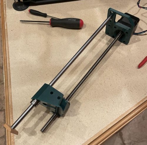
V1 3Z
Intro
This is a 3z mod for the V1 printer which utilizes the original hardware as much as possible to make this a simple upgrade for your printer. It will require an additional stepper and leadscrew to match your current setup, as well as a controller board with capability to drive an extra channel.
This has been tested with an BTT MOT-EXP board on a BTT SKR 1.4 as an inexpensive alternative to a complete board swap.
NOTE: DXF files have been provided with updated motor locations, however the 250 DXF has not been verified. It should be correct but please verify the measurements if you have a 250 build
12 downloads
(0 reviews)0 comments
Submitted
-
V0 Magnetic Panels
This mod comes in two parts, a fixed mounting plate which anchors to the v0 frame with m3x6 screws and a detachable front plate which holds the acrylic panel.
BOM:
Front Panel
6 - M3x6 screws 6 - M3 nuts 22 - 6x3mm magnets Printed parts Side Panel (each)
6 - M3x6 screws 6 - M3 nuts 28 - 6x3mm magnets Assembly instructions:
Front panel
Remove front two feet from V0 Preload 3 m3 nuts to each front extrusion Attach mounting plate to front of V0 with M3x6 screws Insert magnets into the 11 holes on the mounting plate Using VHB tape, affix clear acrlyic to the panel mount part Insert magnets into the 11 holes on the panel mount, be sure to match polarity properly! Re-attach front two feet Side panels
Remove side two feet from V0 Preload 3 m3 nuts to each front extrusion Attach mounting plate to V0 with M3x6 screws Insert magnets into the 14 holes on the mounting plate Using VHB tape, affix clear acrlyic to the panel mount part Insert magnets into the 14 holes on the panel mount, be sure to match polarity properly! Re-attach two feet71 downloads
(0 reviews)0 comments
Submitted
-
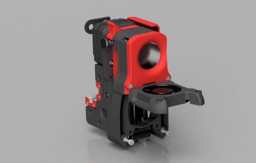
Slenderfan
Slender layer fan for 2.4
About
For the Mosquito hotend, this mod shortens the Afterburner tool head by 10mm along Y. It reduces weight at the maximum lever point on the tool head and gives an open duct so you can service the interior in case of a dropped screw or similar.
You will switch to a smaller layer fan for weight and size benefits, at the cost of maximum air throughput. For ABS, ASA, Nylon and other low-fan materials this is often sufficient but you may struggle with PLA.
There is an option for a prettier 40x10 (the one from 2.2) and a lighter, more utilitarian 50x10 which is better on all counts except cosmetically.
BOM
A Mosquito hotend 6x m3x3.8 heat set inserts 2x m3x12 2x m3x16 2x m3x20 2x m3x30 A: The neat little layer fan from 2.2 B: This ugly layer fan for lighter weight and more air STLs
File Note blower_case.stl blower_lid.stl duct.stl You might need supports. I used supporrt from platform only to keep the inside of the duct clean. hotend_fan_cover.stl You might need supports. I used supports on the duct seal wings to keep them a little nice. v_5010_case.stl For ugly 50x10 style. Replaces blower_case.stl. v_5010_lid.stl For ugly 50x10 style. Replaces blower_lid.stl. Assembly
You are replacing the front half of your print head. You'll need to replace the front mosquito mount with the new shroud, so tear it down a bit (leave your clockwork intact, we're not messing with that) Put in the heat set inserts. 2 on top of blower_lid, 2 in the duct and the 2 on the backside of the duct for bolting the hotend case together. (5010 does not have heat set inserts on the42 downloads
(0 reviews)0 comments
Submitted
-
Closed Bottom
README
Overview
This is my take on fully enclosing the V0. This mod lifts the printer by 10 mm and requires new legs and skirts to be printed. Without further modification this mod can not be printed on a V0 since a bigger build volume is required.
Variants:
I designed two variants of the bottom panel:
Simple: This only requires a rectangular cut (223 mm x 226 mm x 3 mm) bottom panel (can also be printed). The drawback is that the feet have to be removed to access electronics and the feet can only be properly attached with the panel.
Fancy: Requires to cut out to leave out the legs. More loose fit. Non supported corners require stiff panel. Panel can be attached or not independant on the feet.
Requirements:
Single part skirts (too big to print on V0). Legs matching the variant you chose. 3 mm stiff panel cut to shape. I used Dibond and cut it with a jigsaw. 4 x M3 x 40 mm screws for the longer legs. 4 x M3 x 6 mm screws to mount panel and lip. Lip:
The Lip to cover the portion below the spec
3 downloads
(0 reviews)0 comments
Submitted
-
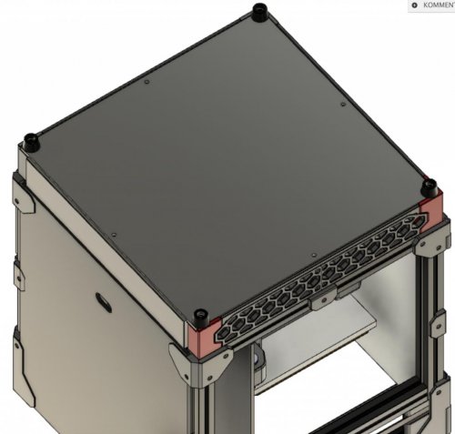
Deck Panel Inserts Logo
README
Overview
Remix of the crew mods deck panel that uses brass heat inserts instead of nylon stand-offs to not have screw heads showing when looking at the printer. Allows inserts 5 mm x 6 mm (shorter 4 mm ones recommended for PSU).
Requirements:
Designed for spec hardware:
PSU: Meanwell LRS-100-24 MCU: BTT SKR Mini E3 1.2 How to print Accent colored Logo
The
3 downloads
(0 reviews)0 comments
Submitted