Search the Community
Showing results for tags 'bobbleheed'.
Found 3 results
-

Version 2021.09.12
781 downloads
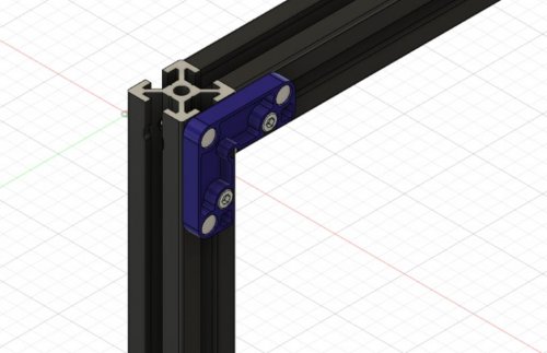
Magnetic Panels This mod allows for the easy removal of the panels on a V2, ideal for switching between ABS and PLA printing. This mod assumes a panel depth of 6mm, either from a 6mm panel or a 3mm panel 3mm foam tape. It will not hold the panels against the frame without this thickness. BOM (for top and side panels) Material Quantity 6x3 Magnets 72 M3x8 SHCS 24 M3 Roll In or Hammerhead T Nuts 24 VHB Tape To reduce the number of magnets required, it is possible to install just two or even one per printed part. This has not been tested and the hold strength unknown. For larger builds or less rigid panels there are also midspan clips which can be used for additional support. BOM (per midspan clip) Material Quantity 6x3 Magnets 4 M3x8 SHCS 1 M3 Roll In or Hammerhead T Nuts 1 VHB Tape Assembly Mount Assembly Pressfit the magnets into the housing. Use the M3x8 SHCS and T Nuts to secure mounts to the frame. It is easiest to install using the regular panel clips to hold the panel in position, this allows the mounts to be positioned with some clearance to the panel allowing smoother attachment of the system following installation. To make full use of this added convenience, fully complete installation of a single clip before repeating the procedure for the remainder on each panel. Cap Assembly Pressfit the magnets into the housing ensuring the poles are aligned between the mount and cap. Apply the triangular section of VHB tape and with the panel in position on the frame lower the magnet side into position before pressing the tape firmly against the panel. The panel can now be pulled straight off the frame for removal, before being replaced with as much ease. Repeat previous steps as required if fitting midspan clips.- 1 review
-
- 5
-

-
- bobbleheed
- v2.4
- (and 1 more)
-
Version 2021.09.12
114 downloads
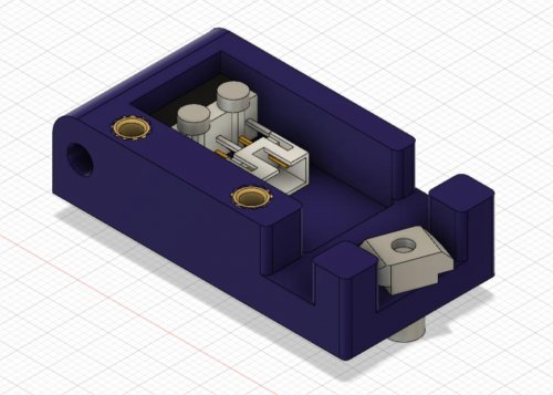
Filament Runout Sensor This mod replaces the stock bowden retainer with one of a similar profile that hides a runout sensor inside. BOM Material Quantity KW10 Microswitch 1 M2x8 SHCS 2 M3x8 SHCS 3 M3 Threaded Inserts 2 M3 Hammerhead T Nut 1 JST 2 OR 3 Pin Housings 1 JST Contacts 2 Glue (CA or Hot) Solder Note: The KW10 microswitch can likely be swapped out for an Omron D2F-5L switch or other equivalents but this hasn't been tested. Optionally, wires could be soldered directly to the microswitch negating the need for the JST terminal. Also two of the M3x8 and the threaded inserts are not required if you do not want to fit a cover over the switch. Assembly Choose the appropriate housing for your printer, either left or right hand (LH or RH) depending on which side you run the reverse bowden to. Print using standard Voron print settings. If you want to use the housing cover use a soldering iron to insert the threaded inserts into the locations as shown above. Insert the switch into the housing with the lever opening facing the wider of the openings on the housing sides. Use the M2x8 to fix it in place. The switch should have clearance to fully open inside. Place the JST terminal inside close to the switch and affixing with glue, bridge the the terminals of the switch and JST with solder in the NO position. Create a cable to connect the switch to your controller board. Fit the cover and attach the sensor to your printer using the M3x8 SHCS and the Hammerhead T Nut. Insert the reverse bowden into the opening on the housing. Klipper Configuration Add the file 'filament_runout.cfg' to your config directory via your GUI and add the line [include filament_runout.cfg] into your 'printer.cfg' file. This configuration assumes the use of dual SKR1.3, you may need to change the pin called out by switch_pin: depending on your setup. If you do not have a M600 macro configured for klipper, change the line pause_on_runout: to true and remove the runout_gcode: section. -
Version 2021.08.29
233 downloads
Magnetic Panels This mod allows for the easy removal of the panels on a V2, ideal for switching between ABS and PLA printing. This mod assumes a panel depth of 6mm, either from a 6mm panel or a 3mm panel 3mm foam tape. It will not hold the panels against the frame without this thickness. BOM (for top and side panels) Material Quantity 6x3 Magnets 72 M3x8 SHCS 24 M3 Roll In or Hammerhead T Nuts 24 VHB Tape To reduce the number of magnets required, it is possible to install just two or even one per printed part. This has not been tested and the hold strength unknown. Assembly Mount Assembly Pressfit the magnets into the housing. Use the M3x8 SHCS and T Nuts to secure mounts to the frame. It is easiest to install using the regular panel clips to hold the panel in position, this allows the mounts to be positioned with some clearance to the panel allowing smoother attachment of the system following installation. To make full use of this added convenience, fully complete installation of a single clip before repeating the procedure for the remainder on each panel. Cap Assembly Pressfit the magnets into the housing ensuring the poles are aligned between the mount and cap. Apply the triangular section of VHB tape and with the panel in position on the frame lower the magnet side into position before pressing the tape firmly against the panel. The panel can now be pulled straight off the frame for removal, before being replaced with as much ease.-
- 2
-
-
- bobbleheed
- v2.4
- (and 1 more)