-
TeamFDM.com is an UNOFFICIAL companion site for the DIY Voron 3D printer community. For official docs and final source of truth, visit the Official Voron Discord or the Voron Github
Printable Voron User Mods
Voron User Mods, or "UserMods", are a collection of community created and Team FDM curated modification for Voron Printers. All of these mods are available on the VoronUsers Github repo and unless otherwise specified follow the Voron communities GPL3.0 Licensing. Use any Mods at your own risk, if you make modification please share them on the VoronUsers repo.
Mod Authors: Have a Voron mod? Upload it at TeamFDM.com and let us know you're the author. We will ensure you can update and curate your files for more feedback! Please include tags for what Voron, or extruder your mod is compatible with.
654 files
-

V0 ZipTie Mount
Overview
Some clips for 1515 extrusions to attach ziptie mounts.
Comes in two flavors for LDO and Makerbeam extrusions.
Zipties can be used horizontal and vertical.
32 downloads
(0 reviews)0 comments
Submitted
-
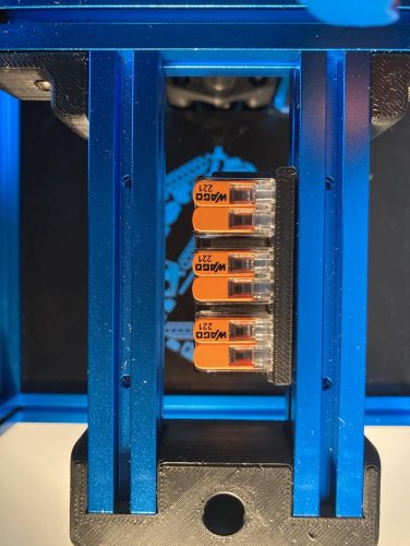
Snap-In Wago Mounts for 1515 extrusions
Overview
This mod is derived from wago_221_mount and brings in some mounts for the Wago 221 terminals (2 and 3 contacts) to clip and to screw for 1515 extrusions.
Wago-Mount for screws
I use this mount WAGO_221-413_3x3-mount-screw.stl at the power inlet to distribute the power to pad/ssr and the PSU. There is also a WAGO_221-412_3x2-mount_screw.stl, if you plan using Wago 221-412 (2 contacts).
Any m3 screw - BHCS or SHCS - should fit.
Snap-In mounts
The snap-in mounts can be easily attached and removed from the extrusions. For using that mount print the desired stl (WAGO_221-412_3x2-mount.stl or WAGO_221-412_5x2-mount.stl together with at least two of the mounting clips(either LDO or MakerBeam depending on your extrusion).
Don't rotate the clips for printing. They must be printed upright, as shown in the picture. Otherwise the clips might break upon inserting into the extrusion.
Use M2 self-tapping screws to attach the clips into the appropriate places of the mount. Screw heads must be flush otherwise the WAGOs won't fit.
Both mounts fit into the Z-Extrusions of the V0
308 downloads
-
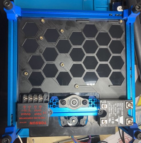
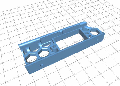
Deck Panel Backpack
Changes
19.10.2020 Updated version with some more space between SKR Board and PSU and some hooks for zipties Overview
This mod brings in a backpack for the V0 Deck Panel.
Imagine you have gotten a deck panel containing a nice print. Surely you don't want to "destroy" this nice print with holes and screws for attaching controller and PSU.
This mod is a modification of Deck_Panel_inserts_logo and thus is designed for the same hardware:
PSU: Meanwell LRS-100-24 MCU: BTT SKR Mini E3 1.2 (tested with 2.0) The backpack can be sticked (e.g. with VHB) against the back of your panel. For mounting the hardware you don't need any standoffs, instead you can use the same heat inserts as for the top head or pocketwatch (M3x5x4).
Below the SKR are some hooks for attaching zipties.
Fusion 360 and Step file is included to ease your own modifications.
5 downloads
(0 reviews)0 comments
Submitted
-
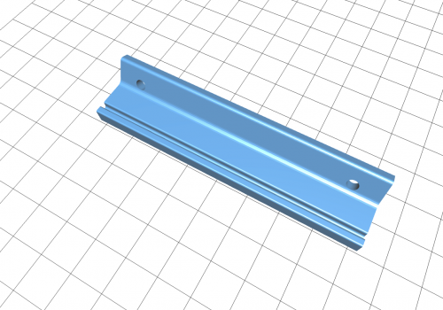
V0 Bowden Fence
Overview
A little "fence" to hold the tubes away from the belts. Clipmount so no further nuts in extrusions are needed.
Print one of the clips (either LDO or Makerbeam) together with the BowdenFence.stl Don't rotate the clips, otherwise they may break upon inserting into the extrusion. They need to be orientated like in the picture
Attach a the clip into the bowdenfence piece with a short M2 self-tapping screw.
20 downloads
(0 reviews)0 comments
Submitted
-
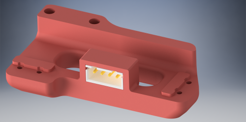
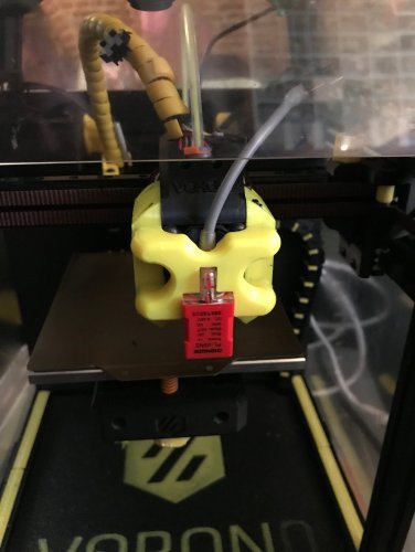
Microswitch POD with Connector
This is a simple modification to the microswitch pod to allow the installation of a JST-XH 4-pin connector.
JST-XH 4-pin connector part number B4B-XH-A(LF)(SN) slides into the hole and there's a small lip to keep it sliding all the way thru.
Depending on your tolerances it may be tight enough as is, or you may have to use a bit of CA glue. You may need to clean up the inside of the slot a bit using a utility knife to get the JST in, as it does involve bridging.
I also slightly increased the size of the screw holes from 1.5mm to 1.7mm as I was having a hard time getting mine screwed down.
27 downloads
- bladescraper-designs
- jst
- (and 1 more)
(0 reviews)0 comments
Submitted
-
Horizontal Spool Holder
Based on the stock spool holder, this mod allows you to mount the spool holder to the horizontal top extrusions, rather than the vertical ones, to allow you to choose between more than just the front or back of the printer. It's sized to fit a KVP 5lb spool or similar, with a 100mm wide area for the spool to sit in. Just like the stock holder, it uses 4mm PTFE tubing to give the spool a nice smooth surface to ride on.
BOM:
2 x M3 T-Nuts
1 x M3x12 SHCS
1 x M3x8 SHCS
1 x Length of PTFE Tubing (Approx 110mm)
To install, first put two M3 T-Nuts into the horizontal extrusion, one on the top and one on the side. Then, put the M3x12 SHCS through the top hole of the holder, and screw it down loosely into the T-Nut. Then, after making sure the side hole is aligned, screw the M3x8 SHCS into the other T-Nut. This screw is technically not required, but does improve strength, as well as keep the holder pointed straight out. Without this screw, the holder will tilt up slightly without the weight of a spool. Far from a deal breaker, but I would generally suggest using both screws.
This part prints without supports and only takes around an hour or less to print with moderate print speeds. Infill isn't critical but I would use at least 3 perimeters and 5 top/bottom layers.
233 downloads
- v2.4
- bladescraper-designs
- (and 1 more)
-
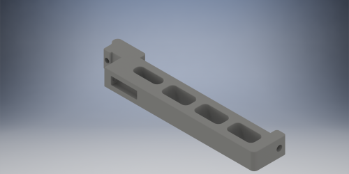
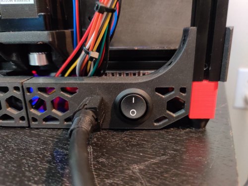
V0 DC Inlet
Adds a skirt-mounted inlet and switch for an external DC power supply, to allow using a DC bed. Options are provided for rear or side mounting.
BOM
Kycon KPJX-PM-4S connector (Digi-Key) Mean Well GST160A24-R7B power supply (Digi-Key) Power switch, 20mm round, rated for at least 7A at 24VDC (Digi-Key) 2x quick disconnect terminal for power switch (Digi-Key) 24V 60W bed heater (Keenovo) 4x M2x10 self tapping screw (For rear skirt only) 4x M3x6 BHCS + 4x M3 hex nut With a 24V bed the SSR is not used, and the bed heater is directly connected to the bed heater output on the controller. I suggest using a SKR Mini E3 V2.0, which can control 2 heaters and 2 fans (unlike V1.2, which has only 3 controllable outputs).
Instructions
For rear mounting, print both skirt_rear files and inlet_bracket.stl. Mirror the skirt pieces if you want the inlet on the right side. Each piece mounts to the rear vertical extrusions with two M3x6 screws. The rear deck panel must be removed. Temporarily remove the rear panel and rear feet to access the extrusion slots.
For side mounting, print skirt_side_with_inlet.stl and inlet_bracket.stl. It replaces an existing skirt piece; mirror it in your slicer if desired.
Inlet and switch mounting steps are shown below. It is suggested to solder wires to the inlet before assembly. Pay particular attention to the order of the inlet pins, and confirm with a multimeter.
6 downloads
(0 reviews)0 comments
Updated
-
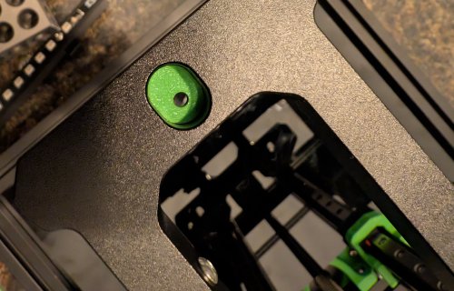
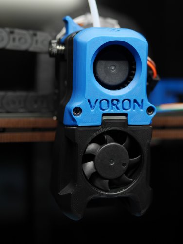
Magnetic Hotend Fan Cover for Afterburner
This replaces the screw-mounted hotend fan cover with one that is held by magnets, for a clean front face and easier access to the toolhead. Works with an unmodified toolhead.
Inspired by ModCables101's magnet mod.
Required hardware
6x3mm round magnet (2x) M3x8 SHCS — steel, not stainless (2x) Instructions
Press the magnets into the new cover. Screw the M3x8 screws into the toolhead until they bottom out; the heads should protrude 4mm from the surface.
43 downloads
- afterburner
- arkeet
- (and 3 more)
(0 reviews)0 comments
Submitted
-
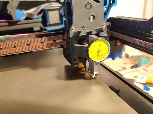
Dial Test Indicator Mount for Afterburner
This replaces the Afterburner toolhead with a dovetail mount for a dial test indicator (such as a Mitutoyo 513-404, which this was modelled on). The indicator point is ideally located at the same position as the nozzle (the precise Y position may vary depending on the length of the tip). There is a protrusion where the nozzle would be located, so that Z homing can be done normally as though a nozzle were present.
This can be used, for instance, to verify whether a mesh reflects the true form of the bed surface: sweeping the bed with the mesh enabled would ideally show no movement on the indicator.
Required hardware
M3x8 SHCS (4x) M3 hex nut (2x)42 downloads
- afterburner
- arkeet
- (and 4 more)
(0 reviews)0 comments
Submitted
-
MGN12 X axis
This replaces the dual MGN9H rails on the V2.4 X axis with a single MGN12H rail. The belt is directly clamped to the MGN12 block by the carriage.
The stock PL-08N probe might be too long to fit. Recommended alternatives are listed below.
As an option, the x_carriage_frame_right_endstop.stl allows mounting the X endstop switch on the carriage, which is useful on an umbilical cable setup.
Thanks to joshmurrah, hartk, and everyone else who helped out in one way or another.
Required hardware
In addition to things you can reuse from the stock build, these items are required:
1x MGN12 linear rail with MGN12H carriage (same length as the original MGN9 rails) 1x M3x40 SHCS 4x M3x8 BHCS (or 2x BHCS and 2x SHCS) Recommended probes:
Omron TL-Q5MC2 (use M3x25 or M3x30 screws) Panasonic GL-18HB/18HLB (use M3x25 or M3x30 screws) Panasonic GX-H15B/HL15B (use the 9mm probe bracket, and M3x16 or M3x20 screws) Instructions
Assembly is similar to stock V2.4, see the assembly images below.
The belts are clamped between the carriage and the MGN12H block. This procedure worked for me:
Loosely fasten the carriage to the MGN12H block using the M3x8 screws. Push the belts in on the left side, until they are just visible in the middle. Tighten the screws on the left side a little bit, to secure the belt ends. Push the belts in on the right side as far as you can, and pull them out through the middle. Tighten all screws, while making sure that all belts are firmly held in the clamp teeth. You may wrap the extra length of belt around the probe cable, as in the photo below. Please check the Z endstop position after assembly as it may have changed slightly.
Changelog
2021-03-28
Added option for mounting X endstop on the carriage. Updated readme to note that stock PL-08N probes might fit. 2021-03-21
Initial release471 downloads
-
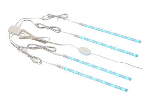
Voron 2.x IKEA Dioder Led Mount
Overview
Voron 2.x IKEA Dioder Led Mount for the DIODER single and multi colour LED Strip sold by IKEA.
Description
This is an improved version of the model of randommen96 for the IKEA Dioder LED strip.
It comes with a wider gap so it nicely fits the metal mounting brackets supplied with the Dioder. Additionally the strip can be mounted either with VHB tape or an M3x8 BHCS screw. The LED shines inwards in an angle of 70°. Step file is included to ease your own modifications.
4 downloads
(0 reviews)0 comments
Submitted
-
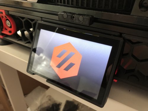
BTT PITFT50 v2 Mount
This work is based on sttts's Waveshare 5.5inch mount. BTT PITFT50 v2 has a different layout than v1, featuring a brightness thumbwheel, an orientation switch and a JST XH port for unknown function. This design provide accessibility to the thumbwheel and switch.
BOM
4x M3x6mm 4x M2.5x4mm (included in the BTT PITFT50 v2) 500mm ~ 600mm Ribbon Flat Cable for Raspberry Pi Camera (depends on the position of the Raspberry Pi. The included one is too short) Instructions
Please use the mount in sttts's mods to amount this to the frame. No re-print of skirts is required!
Print Settings
Standard Voron recommended print settings
612 downloads
-
V0 PL05N2 Mount
Mount for PL05N2 Sensor.
Designed for this model, but others may fit. https://www.aliexpress.com/item/32805983692.html
Print 1 of each STL.
Requires 8 x 6mmx3mm Round Neodymium Magnets.
This is designed for temporary installation to level bed and build bedmesh.
0 downloads
(0 reviews)0 comments
Submitted
-
V0 LED Mount
Led holder for WS2812 type LED strings, includes channel for data line to loop back for second strip.
Includes additional print support (between led strip retainers), which needs to be removed before use. Mounts on top of the top extrusion, using 2 M3 bolts per strip, two strips required per side, (so they can be printed on V0). It does not interfere with the top hat.
17 downloads
(0 reviews)0 comments
Submitted
-
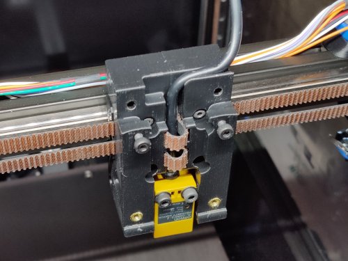
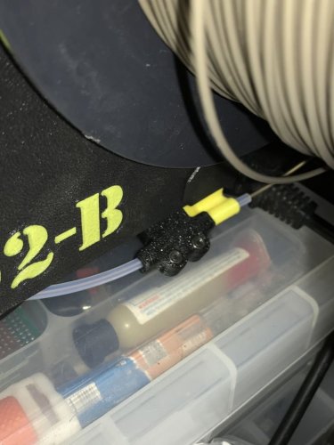
Filament Detection
Voron themed filament detection.
I fancied making my own simple filament detection module, using spares from my Voron V0 build, and here it is..
BOM
4x M3 Nut 4x M3x6 bolt (SH/BH) 2x M2x10 Self Tapping Screws 1x Omron Mouse Button - Micro Switch Bowden tube can be inserted to guide the filament in to the module, you might need to fettle this, as it maybe a bit tight and restrict the filament movement. There should be very little friction if all goes well.
The module works in either direction, it should be mounted away from the extrusion motor, as klipper buffers commands, so the further from the motor the better.
I printed with 0.4mm nozzle 0.2mm layer height, no supports need.
Print one of each STL.
9 downloads
(0 reviews)0 comments
Submitted
-
Skirt Mount for V0 for Analog Timer
Skirt mount for V0, to allow mounting of analog timer.
Mounts in back/right position.
Fits https://www.aliexpress.com/item/799301917.html, or similar.
1 download
(0 reviews)0 comments
Submitted
-
Misaligned Rail Tools
Overview
In the initial Afterburner beta, I found that I had an inconsistent first layer height which I could not fix with bed_mesh or QGL. I suspected a twisted x extrusion. I found it is possible to very slightly misalign the x rails to produce an apparent extrusion twist, and I was able to fix it using simple tools and a few printed parts.
The Dozuki article goes into a lot more detail, but here you will find the broad strokes and the tools I used.
I take no responsibility for anything happening to you, your printer, or anything else should you follow what I did.
The Issue
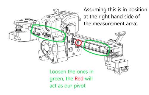
This diagram shows what I think is going on. In the AB beta, you align and install the front rail, then align the bottom rail to it. If the front rail is slightly misaligned higher on the left/lower on the right (black arrows), it will pull up on the carriage (blue arrow pointing up) when moved to the left (green arrow). The bottom rail is constrained in that direction, so it moves forward(red arrow).
It is the combination of the blue and red arrows which cause the apparent twist, tilting the carriage away from the build plane. Quad_Gantry_Level can and does correct for a single rail misalign (such as on a V2.2) but once there are 2 rails perpendicular to each other, they impart twist which QGL cannot fix.
From my measurements I was approx. 0.07mm higher on left than on the right. Over the length of the rail, this can impart a twist of approx 0.4 degrees. At the nozzle I had a variance of .12mm in layer height over approx. 150mm
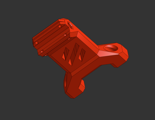
Requirements
metal ruler/light Dial indicator (1 inch travel, .001 resolution) Printed Dial Indicator adapter (this mod) Printed adjuster assembly (this mod) If you do not have a dial indicator it may be possible to test for this using a z-height/paper gauge test. in this case you won't need the dial indicator stl, just the adjuster stls
Detection
The Dozuki article has the detail here, but the general idea is to use either a dial indicator or paper test the nozzle height at different x locations. Since we are at QGL, and assuming the bed is flat, there should be little measured change.
The Fix (Dangerous)
Assemble the "adjuster" like so:
DO NOT INSTALL YET DANGER! If you install this and then do a home, bad things will happen as the adjuster will hit the stepper long before the y switch activates. be very very careful when this is installed.
16 downloads
(0 reviews)0 comments
Updated
-
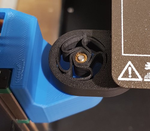
Voron 2.2-2.4 Precision A/B Drive System
Overview
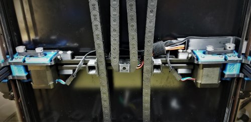
This is actually 2 mods in one. The first mod increases resolution and torque of the AB drives. The second mod inverts and strenghtens the ab drive frames. you can do either mod independently, they do not rely on each other. If you are going to do them both, do them at the same time as they both require gantry disassembly.
IMPORTANT NOTE for 2.4: This mod was designed to fit with the 2.2 sized extrusions. For a Voron 2.2 the back extrusion measures 40 mm shorter than the back extrusion in a Voron 2.4. You can do this mod on a 2.4, but you will have to either buy a new extrusion which is shorter or cut the one you have. I suggest buying a new one, so you can go back to the 2.4 drives at will.
Drive reduction
In the Voron 2.2, the A and B drives have a closed belt that drives the driveshaft which powers the xy gantry movement. In the spec 2.2, all 3 pulleys are 20T pulleys. This means the torque at the open belt is equal to the torque at the stepper motor, and the step size is (2mm pitch * 20 Teeth)/(200 steps * 16 microsteps)=0.0125 mm/microsteps
In this mod we are replacing 2 of these pulleys with 16 tooth pulleys. We replace the one on the stepper and the one that drives the open belt. This gives us a step size of (2mm*16)/250 steps *16 micro)0.008 mm/step the 16:20:16 reduction gear increases the torque at normal print speeds. This affect tapers off at higher speeds because our stepper is running at a higher RPM compared to the spec drive.
Frame strengthening and inverting.
I took this opportunity to also strengthen the ab drive frames which had begin to crack at the extrusions on my 2.2. I also inverted the drives to put the spinny bits in view.
Disclaimer: It is your printer. If you do this and something breaks, it is fully your responsibility. I take no responsibility.
Materials needed
Spec Voron 2.2 or 2.4 4 GT2 16T pulleys 6mm wide, 5mm bore 4 new printed frame parts (this mod) (for 2.4 only) a new extrusion 40 mm shorter than your back extrusion Procedure:
Print the new frames at Voron print specifications (ABS, 40% 0.2 layer height) Remove the old AB drives and disassemble Assemble using the new frames and 16T gears as shown Modify ab stepsize in firmware Recommission printer Assembly
It is important to get the 16 tooth gears and the 20 tooth gears in the right locations. The stepper and the gear that contacts the open belt on the driveshaft are 16 tooth. The gear connecting the closed 110 mm loop to the shaft is still a 20 tooth.
Firmware (klipper)
In your printer.cfg you must make this change: [stepper_x] ... step_distance: 0.008 ##for gear reduction drive
... [stepper_y] ... step_distance: 0.008 ##for gear reduction drive
I cannot recall if you have to reverse the direction pins or not. in my current working config, they are reversed. [stepper_x] ... dir_pin: !P2.6 #this is for a skr 1.4 pro using 2209 drivers. your pin and dir may vary
[stepper_y] ... dir_pin: !P0.20 #this is for a SKR 1.4 pro using 2209 drivers. your pin and dir may vary
Recommission
Treat this printer like it's just been built, because it's a new printer. It is very easy to accidentally pull a wire or drop a connection
Go slowly. Verify the steppers with stepper_buzz. Carefully home the xy. if they move in the wrong direction, stop the printer. Check gantry alignment. Retension the belts. Enjoy!48 downloads
(0 reviews)0 comments
Submitted
-
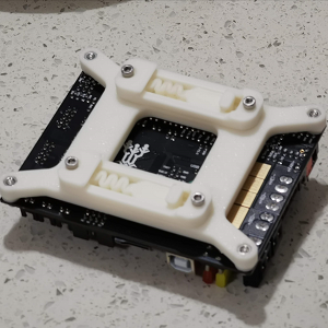
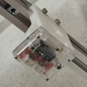
Voron 2.4 SKR 1.3/1.4 Mount for DIN Rail
G'day, another nice thingy from down under. Got non-standard electronics compartment? Some blocks there that don't allow spec placements? Don't have or don't like self-tapping screws? Or are you just up to better wiring and sturdier construction? Alright, Dropbears to rescue. Here comes a rigid bracket for SKR boards, that uses M3 bolts and nuts, and allows mounting along and across the rail. Each bracket needs 2 of rs25_psu_bracket_clip.stl.
Printing and Plastic
Standard Voron part printing guidelines to follow: 0.4 nozzle, 0.2 layer height, etc.
This part is not exposed to any significant heat, so you could probably use even PLA.
Assembly
BOM:
8 x M3 hex nuts 8 x M3x12 SHCS screws Credits
that russian guy (aeresov#9959) A Team Dropbear Production
35 downloads
-
Voron 2.4 MeanWell UHP PSU Mount for DIN Rail
G'day, another nice thingy from down under. MeanWell UHP PSUs are great: nice, slim, compact, mains and DC on opposite sides... Well, but how to mount them on DIN rails? Alright, Dropbears to rescue. Pick an adapter for your UHP (they have different width), print 2 of them and 4 of rs25_psu_bracket_clip.stl.
Printing and plasic
Standard Voron part printing guidelines to follow: 0.4 nozzle, 0.2 layer height, etc.
This part is not exposed to any significant heat, so you could probably use even PLA.
Assembly
BOM:
8 x M3 hex nuts 8 x M3x12 SHCS screws 4 x M3 suare nuts 4 x M3x10 SHCS screws Put square nuts in slide pockets, secure them with screws, then bolt down rs25 brackets, so square nuts are trapped.
Credits
that russian guy (aeresov#9959) A Team Dropbear Production
120 downloads
(0 reviews)0 comments
Submitted
-
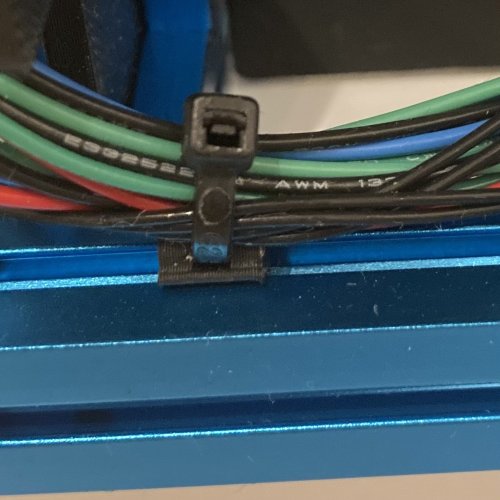
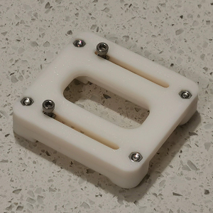
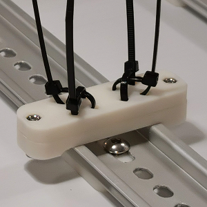
Voron 2.4 Cable Tie Mount for DIN Rail
G'day, another nice thingy from down under: a simple bracket that allows fixing your cables with standard 3.5mm plastic cable ties in various positions. 4 ties per bracket, 2x2 criss-cross, so you can make bends or straights. The bracket needs 1 of rs25_psu_bracket_clip.stl.
Printing and Plastic
Standard Voron part printing guidelines to follow: 0.4 nozzle, 0.2 layer height, etc.
This part is not exposed to any significant heat, so you could probably use even PLA.
Assembly
BOM:
2 x M3 hex nuts 2 x M3x12 SHCS screws standard 3.5mm cable ties Credits
that russian guy (aeresov#9959) A Team Dropbear Production39 downloads
(0 reviews)0 comments
Submitted
-
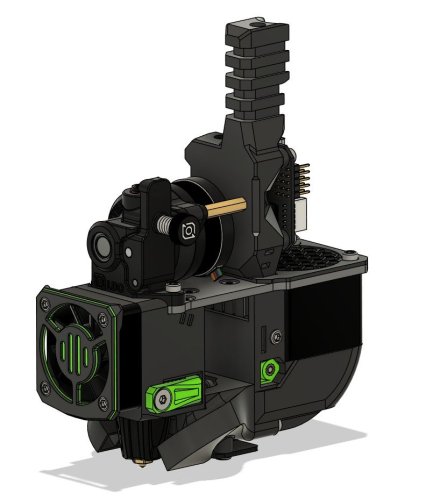
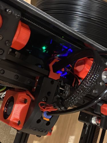
Voron 2.4 Trianglelab Filament Sensor Bracket
G'day, another nice thingy from down under. Got TL filament sensor in your pile of parts? Bought it a year ago for 2.1 and too lazy to find a way to mount it so it plays well with spool holder? Upgraded to 2.4 and still have no clue? Alright, ask a mate to hold your beer, this is quick one: just print it and use instead of stock bowen_retainer.stl.
Printing and Plastic
Standard Voron part printing guidelines to follow: 0.4 nozzle, 0.2 layer height, etc.
Any common plastic will do, this is outer part with no heat exposure.
Well, sure, you can print it in PEEK if you're that guy.
Assembly
BOM:
2 x M3 t-nuts 4 x M3x12 SHCS screws 2 x M3 heat inserts (4mm will do) Bolt your sensor to it, insert your PTFE tube to sensor's exit hole.
Make Melbourne hipsters proud, do your wiring in braided sleeving and with fancy connectors. And have a flat white when you're done.
Credits
that russian guy (aeresov#9959) A Team Dropbear Production88 downloads
-
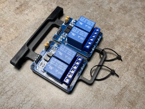
Relay Mount
Simple relay-mount for 2x 2 channel relay modules - e.g. for moonraker power plugin.
Mount with two M5x8 screws and T- or hammerhead nuts to normal 2020 extrusions.
4x or 8x M2x8 self tapping screws to mount the relay module.
6 downloads
(0 reviews)0 comments
Submitted
-
G1 Exhaust Filter Housing
Exhaust filter housing with the G1-8" thread on the side. Can also simply be printed mirrored to have the fitting on the opposite side
38 downloads
-
Corner Panel Clip
Corner panel clip with an internal cable path, so you can route the cables around the panel and corner.
I use them to mount 6mm floatglas as top panel with 3mm foam tape
corner_panel_clip_top_4mm.stl is 4mm and corner_panel_clip_bottom_3_5mm.stl is 3.5mm height,
so at the end there is 7.5mm space for the panel and foamtape.
Needs 2x M3x12 screews to mount per clip.
135 downloads
(0 reviews)0 comments
Submitted

-
Most Actively Discussed Mods
-
Hottest Files!