Search the Community
Showing results for tags 'v2.2'.
Found 3 results
-

Version 1.0.0
4 downloads
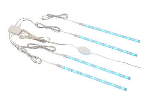
Overview Voron 2.x IKEA Dioder Led Mount for the DIODER single and multi colour LED Strip sold by IKEA. Description This is an improved version of the model of randommen96 for the IKEA Dioder LED strip. It comes with a wider gap so it nicely fits the metal mounting brackets supplied with the Dioder. Additionally the strip can be mounted either with VHB tape or an M3x8 BHCS screw. The LED shines inwards in an angle of 70°. Step file is included to ease your own modifications. -
Version 1.0.0
15 downloads
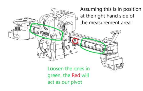
Overview In the initial Afterburner beta, I found that I had an inconsistent first layer height which I could not fix with bed_mesh or QGL. I suspected a twisted x extrusion. I found it is possible to very slightly misalign the x rails to produce an apparent extrusion twist, and I was able to fix it using simple tools and a few printed parts. The Dozuki article goes into a lot more detail, but here you will find the broad strokes and the tools I used. I take no responsibility for anything happening to you, your printer, or anything else should you follow what I did. The Issue This diagram shows what I think is going on. In the AB beta, you align and install the front rail, then align the bottom rail to it. If the front rail is slightly misaligned higher on the left/lower on the right (black arrows), it will pull up on the carriage (blue arrow pointing up) when moved to the left (green arrow). The bottom rail is constrained in that direction, so it moves forward(red arrow). It is the combination of the blue and red arrows which cause the apparent twist, tilting the carriage away from the build plane. Quad_Gantry_Level can and does correct for a single rail misalign (such as on a V2.2) but once there are 2 rails perpendicular to each other, they impart twist which QGL cannot fix. From my measurements I was approx. 0.07mm higher on left than on the right. Over the length of the rail, this can impart a twist of approx 0.4 degrees. At the nozzle I had a variance of .12mm in layer height over approx. 150mm Requirements metal ruler/light Dial indicator (1 inch travel, .001 resolution) Printed Dial Indicator adapter (this mod) Printed adjuster assembly (this mod) If you do not have a dial indicator it may be possible to test for this using a z-height/paper gauge test. in this case you won't need the dial indicator stl, just the adjuster stls Detection The Dozuki article has the detail here, but the general idea is to use either a dial indicator or paper test the nozzle height at different x locations. Since we are at QGL, and assuming the bed is flat, there should be little measured change. The Fix (Dangerous) Assemble the "adjuster" like so: DO NOT INSTALL YET DANGER! If you install this and then do a home, bad things will happen as the adjuster will hit the stepper long before the y switch activates. be very very careful when this is installed. -
Version 1.0.0
36 downloads
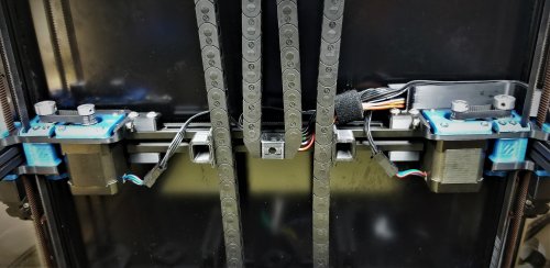
Overview This is actually 2 mods in one. The first mod increases resolution and torque of the AB drives. The second mod inverts and strenghtens the ab drive frames. you can do either mod independently, they do not rely on each other. If you are going to do them both, do them at the same time as they both require gantry disassembly. IMPORTANT NOTE for 2.4: This mod was designed to fit with the 2.2 sized extrusions. For a Voron 2.2 the back extrusion measures 40 mm shorter than the back extrusion in a Voron 2.4. You can do this mod on a 2.4, but you will have to either buy a new extrusion which is shorter or cut the one you have. I suggest buying a new one, so you can go back to the 2.4 drives at will. Drive reduction In the Voron 2.2, the A and B drives have a closed belt that drives the driveshaft which powers the xy gantry movement. In the spec 2.2, all 3 pulleys are 20T pulleys. This means the torque at the open belt is equal to the torque at the stepper motor, and the step size is (2mm pitch * 20 Teeth)/(200 steps * 16 microsteps)=0.0125 mm/microsteps In this mod we are replacing 2 of these pulleys with 16 tooth pulleys. We replace the one on the stepper and the one that drives the open belt. This gives us a step size of (2mm*16)/250 steps *16 micro)0.008 mm/step the 16:20:16 reduction gear increases the torque at normal print speeds. This affect tapers off at higher speeds because our stepper is running at a higher RPM compared to the spec drive. Frame strengthening and inverting. I took this opportunity to also strengthen the ab drive frames which had begin to crack at the extrusions on my 2.2. I also inverted the drives to put the spinny bits in view. Disclaimer: It is your printer. If you do this and something breaks, it is fully your responsibility. I take no responsibility. Materials needed Spec Voron 2.2 or 2.4 4 GT2 16T pulleys 6mm wide, 5mm bore 4 new printed frame parts (this mod) (for 2.4 only) a new extrusion 40 mm shorter than your back extrusion Procedure: Print the new frames at Voron print specifications (ABS, 40% 0.2 layer height) Remove the old AB drives and disassemble Assemble using the new frames and 16T gears as shown Modify ab stepsize in firmware Recommission printer Assembly It is important to get the 16 tooth gears and the 20 tooth gears in the right locations. The stepper and the gear that contacts the open belt on the driveshaft are 16 tooth. The gear connecting the closed 110 mm loop to the shaft is still a 20 tooth. Firmware (klipper) In your printer.cfg you must make this change: [stepper_x] ... step_distance: 0.008 ##for gear reduction drive ... [stepper_y] ... step_distance: 0.008 ##for gear reduction drive I cannot recall if you have to reverse the direction pins or not. in my current working config, they are reversed. [stepper_x] ... dir_pin: !P2.6 #this is for a skr 1.4 pro using 2209 drivers. your pin and dir may vary [stepper_y] ... dir_pin: !P0.20 #this is for a SKR 1.4 pro using 2209 drivers. your pin and dir may vary Recommission Treat this printer like it's just been built, because it's a new printer. It is very easy to accidentally pull a wire or drop a connection Go slowly. Verify the steppers with stepper_buzz. Carefully home the xy. if they move in the wrong direction, stop the printer. Check gantry alignment. Retension the belts. Enjoy!