

-
 4
4
About This File
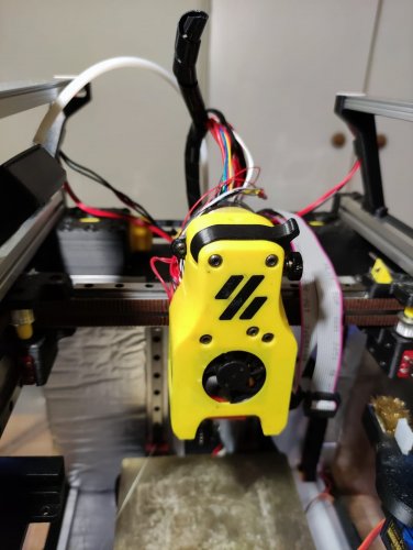
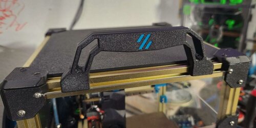
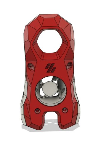
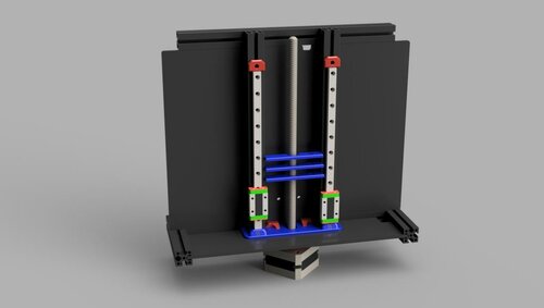
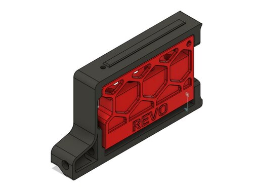
I wanted to create an invisible filament sensor inside the toolhead to check if the filament runs out or if there is a clog in the extruder gears. Tested on Dragon normal flow, not tested on Dragonfly, but it should work.
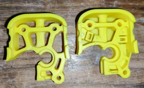
https://github.com/diego589/Mini-AB-Filament-Sensor/raw/main/Images/Comparison.jpeg
BOM
For both (before and after the extruder's gears)
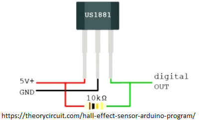
- 2x digital hall sensor, it doesn't matter if it's latching or not. I'm using U18
- 7x 4mm ball bearings
- 4x 5mm x 3mm Round Neodymium Magnets
- 2x 10k ohm resistor
- Thin wires, 32 AWG recommended
BOM If you only want a sensor before the gears:
- 1x Digital hall sensor
- 1x ball bearing
- 2x Magnets
- 1x resistor
- Thin wires
BOM If you only want a sensor after the gears:
- 1x Digital hall sensor
- 6x ball bearings
- 2x Magnets
- 1x resistor
- Thin wires
Tools
- Multimeter
Printed parts
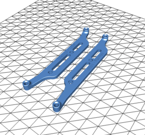
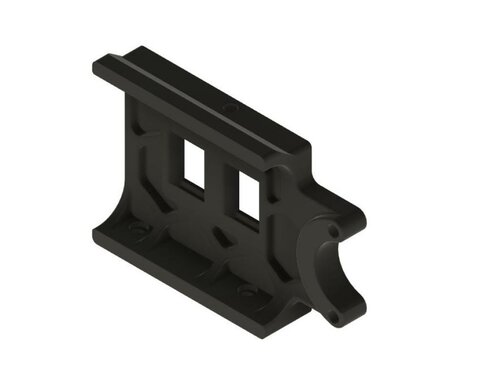
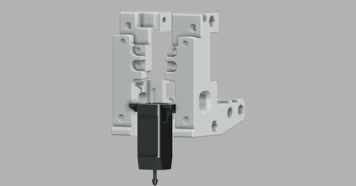
- [a]FS_Mid_Body.stl - Needed
- Recommended to print 2 copies of every hall sensor holder
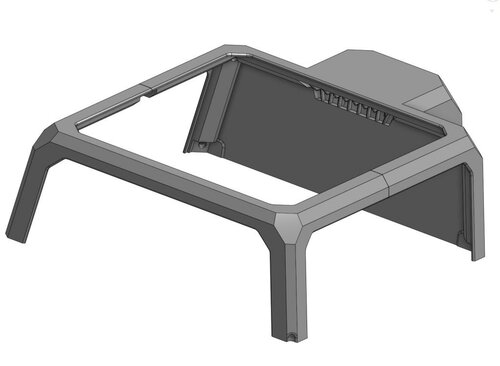
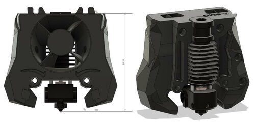
- [a]FS_Cowling_Dragon.stl - Not needed at all, but print it if you don't want to sand it down (step 13)
Assembly
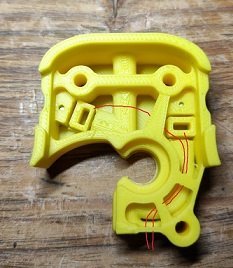
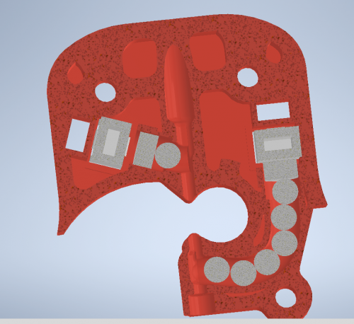
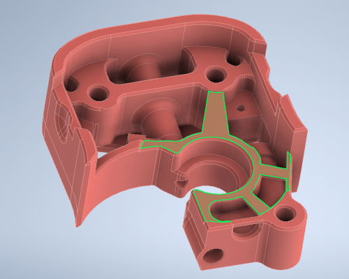
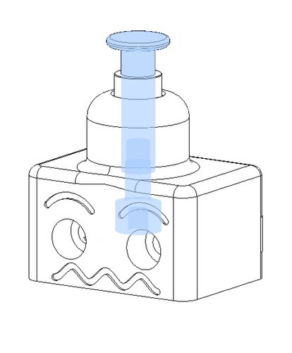
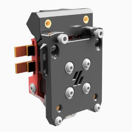
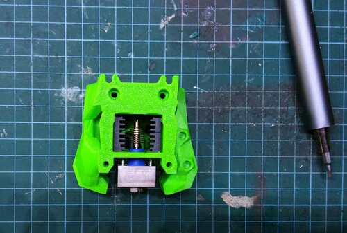
- Insert 6 balls in 1
- Insert magnet in 1
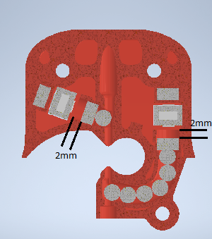
- Make sure that magnet is around 2mm down the tunnel, if not, then push it using filament or something similar
- Test your clearances by inserting filament, when there is no filament the magnet should be 2mm down the tunnel and when the filament is loaded, the magnet should raise up about 2mm
- Insert a magnet in 3, it should repel the magnet in 1. If you inserted it in the wrong orientation use an 1.5 or 2mm drill bit to remove it out of the hole
- Prepare hall sensor, solder resistor at no less than 10 cm from the sensor
- Test your circuit, move the hall sensor towards each magnets and check with a multimeter between GND and OUT, it should read 5v next to one and 0v next to the other
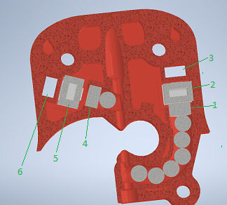
- Insert the hall sensor in [a]HallSensorHolder145-145.stl, then insert the holder with the sensor in 2 (small face of sensor pointing towards 3). DO NOT force it yet
- Load and unload filament and check with a multimeter if there is any variation, if the voltage doesn't change, rotate hall sensor and repeat
- If everything is working, push the hallsensor holder in place
- If it's not working, remove it and try with a different sensor holder, then repeat
- For the sensor that goes before the gears follow the same instructions but use just 1 ball bearing instead
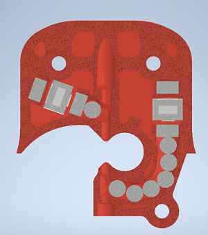
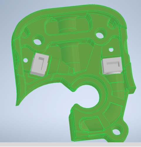
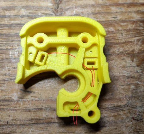
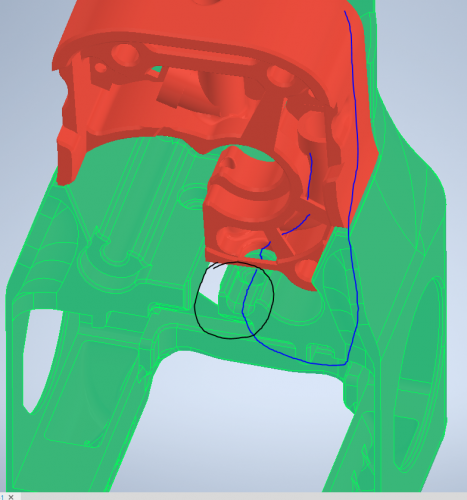
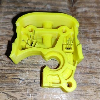
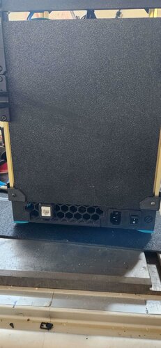
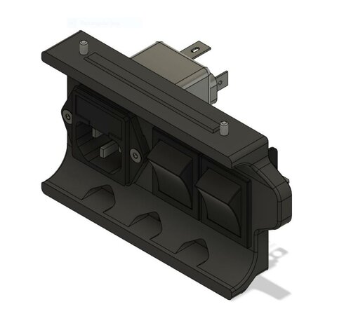
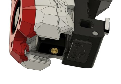
- Bend the sensor pins until they are below the highlighted part (image below)
- Route your cable following the path as shown in the image below. If you didn't print [a]FS_Cowling_Dragon.stl you have to sand a path down yourself (black circle in image below)
- Choose any available pin on your board. In this case I am using RX2 and TX2 because they are right next to GND and +5v. See TestCode.txt


