Search the Community
Showing results for tags 'afterburner mini'.
Found 2 results
-


Version 1.0.0
191 downloads
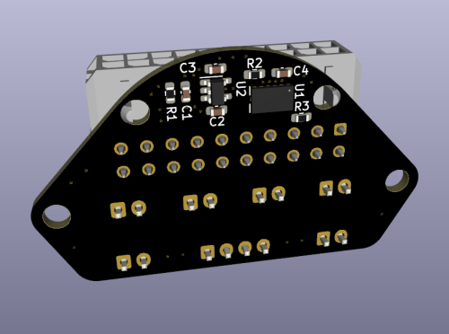
The Voron-0 Umbilical is a well known and very useful addition to your 3D Printer, originally created by GitHub user timmit99 and can be found in the official Voron-Hardware repository here. In this new 'Plus' version, I have added a permanent ADXL345 Accelerometer to the Toolhead board, to make input shaper tuning (and possibly other interesting use-cases) more accessible to users. The Molex MicroFit connector was changed from a 14-pin to 20-pin version to acommodate the additional wires for the ADXL345. The Toolhead PCB can be ordered pre-assembled from JLCPCB (using the included CPL and BOM file) so you do not have to solder the delicate electronics yourself, just the connectors (as you need to do with the original V0-Umbilical). You can find a full README and Photos/CAD/Design data at my github repository: https://github.com/skuep/V0-Umbilical-Plus Frame PCB BOM Part Quantity Notes LCSC Part Number Link 20 Pin Socket 1 MOLEX 430452012 C485575 https://www.lcsc.com/product-detail/Wire-To-Board-Wire-To-Wire-Connector_MOLEX-430452012_C485575.html SMD Thermistor 1 100K 0805 Thermistor C143680 https://lcsc.com/product-detail/NTC-Thermistors_Vishay-Intertech-NTCS0805E3104FXT_C143680.html 2 pin JST XH 5 2.5mm pitch C158012 https://lcsc.com/product-detail/Wire-To-Board-Wire-To-Wire-Connector_JST-Sales-America-B2B-XH-A-LF-SN_C158012.html 3 pin JST XH 2 2.5mm pitch C144394 https://lcsc.com/product-detail/Wire-To-Board-Wire-To-Wire-Connector_JST-Sales-America-B3B-XH-A-LF-SN_C144394.html 4 pin JST XH 3 2.5mm pitch C144395 https://lcsc.com/product-detail/Wire-To-Board-Wire-To-Wire-Connector_JST-Sales-America-B4B-XH-A-LF-SN_C144395.html 6 pin JST XH 1 2.5mm pitch C144397 https://www.lcsc.com/product-detail/Wire-To-Board-Wire-To-Wire-Connector_JST-Sales-America_B6B-XH-A-LF-SN_JST-Sales-America-B6B-XH-A-LF-SN_C144397.html Screw Terminal 1 5.08mm pitch C8465 https://lcsc.com/product-detail/Screw-terminal_Ningbo-Kangnex-Elec-WJ500V-5-08-2P_C8465.html Optional Parts Part Quantity Notes LCSC Part Number Link 0805 10uF Capacitor 3 Use if using BARE neopixel IC's. Strips have these already. C17024 https://lcsc.com/product-detail/Multilayer-Ceramic-Capacitors-MLCC-SMD-SMT_Samsung-Electro-Mechanics-CL21A106KPFNNNE_C17024.html Toolhead PCB BOM Part Quantity Notes LCSC Part Number Link 20 Pin Socket (Right Angle) 1 Molex 430452000 C485576 https://www.lcsc.com/product-detail/Wire-To-Board-Wire-To-Wire-Connector_MOLEX-430452000_C485576.html 2 pin JST XH 6 B2B-XH C158012 https://lcsc.com/product-detail/Wire-To-Board-Wire-To-Wire-Connector_JST-Sales-America-B2B-XH-A-LF-SN_C158012.html 4 pin JST XH 1 B4B-XH C144395 https://lcsc.com/product-detail/Wire-To-Board-Wire-To-Wire-Connector_JST-Sales-America-B4B-XH-A-LF-SN_C144395.html LP2985-33DBVR 1 3.3V LDO C95414 https://www.lcsc.com/product-detail/Linear-Voltage-Regulators-LDO_Texas-Instruments-LP2985-33DBVR_C95414.html ADXL345BCCZ 1 Accelerometer C9667 https://www.lcsc.com/product-detail/Motion-Sensors-Accelerometers_Analog-Devices-ADXL345BCCZ-RL7_C9667.html 10 Ohm Resistor 2 0603 size C22859 https://www.lcsc.com/product-detail/Chip-Resistor-Surface-Mount_UNI-ROYAL-Uniroyal-Elec-0603WAF100JT5E_C22859.html 10 kOhm Resistor 1 0603 size C25804 https://www.lcsc.com/product-detail/Chip-Resistor-Surface-Mount_UNI-ROYAL-Uniroyal-Elec-0603WAF1002T5E_C25804.html 4.7uF Capacitor 2 0603 size C19666 https://www.lcsc.com/product-detail/Multilayer-Ceramic-Capacitors-MLCC-SMD-SMT_Samsung-Electro-Mechanics-CL10A475KO8NNNC_C19666.html 10nF Capacitor 2 0603 size C57112 https://lcsc.com/product-detail/Multilayer-Ceramic-Capacitors-MLCC-SMD-SMT_10nF-103-10-50V_C57112.html/?href=jlc-SMT Corresponding CPL and BOM files are included in the repository. Using these files you can easily get yourself a ready-made assembled PCB from JLCPCB so you don't have to have the skills to solder the fine-pitch and 0603 packages. Umbilical cable The Umbilical cable is a 220-240mm dual ended 20P (2x10) microfit cable. The connectors are wired 1:1 so pin 1 connects to pin 1 and so forth for all 20 pins. Cable BOM Part Quantity Notes LCSC Part Number Link 20 Pin Plug 2 Molex 430252000 C485324 https://lcsc.com/product-detail/Connectors-Housings_MOLEX-430252000_C485324.html Crimps 20 AWG 12 Molex 430300001/430300007 C259786 https://lcsc.com/product-detail/Line-Pressing-Terminals_MOLEX-430300001_C259786.html Crimps 26 AWG 28 Molex 430300004/430300010 C259765 https://lcsc.com/product-detail/Line-Pressing-Terminals_MOLEX-430300004_C259765.html 20AWG Wire 12 220mm Sections PTFE/Silicone/Hefulon for motion rated, PVC could work since it isn't constraind to a cable chain 26AWG Wire 28 MicroFit connectors support two different ranges of conductor thickness using different wire crimp ferrules. I recommend that you realize the stepper motor and heater wires with 20AWG wire (0.5mm²) and the remaining wires in 26AWG wire (0.14mm²) to save on weight and accelerated mass. Hints and Remarks Extruder Stepper Direction The umbilical cable reverses the stepper rotation direction. I.e. you need to invert the DIR pin of the extruder motor in your printer.cfg file. [extruder] .... dir_pin: PB4 # Add ! (or remove ! if already there) before 'PB4' .... Mounting the Toolhead PCB The umbilical toolhead PCB uses heat stake inserts in order to mount it to the motor screws. In some cases (i.e. LDO motors), the extruder motor already has an additional thread, which has to be either removed by drilling the motor holes with a 3mm spiral drill. If you do not want to drill into the motor, you can use M3x10 captive screws, which are unfortunately hard to find. These screws have a narrowed section and a short thread at the tip so they only 'grab' the thread of the heat stake inserts. Additional chamber thermistor on SKR mini V2.0 If you are using the SKR mini V2.0 board and you want to connect the chamber thermistor, you can use Timmit99's expansion board (https://github.com/VoronDesign/Voron-Hardware/tree/master/SKR-Mini_TFT_Thermistor_Board). If you want an easier and faster solution, you can move the Z-STOP endswitch pin and connect it the E0-STOP pin using a simple self-made JST 2-pin to 3-pin adapter (See Photos folder) or by removing the crimp pins from the 2-pin JST and insert them into the housing of a 3-pin JST header. Once the Z-STOP pin is freed up, you can use it for your thermistor. This method needs the following printer.cfg changes: [stepper_z] ... endstop_pin: ^PC15 # Conversion for additional thermistor (use E0-STOP for Z-STOP) ... [temperature_sensor chamber] sensor_type: Generic 3950 sensor_pin: PC2 gcode_id: C pullup_resistor: 10000 Connecting the ADXL345 to a Raspberry Pi The ADXL345 circuit on the toolhead PCB includes a R-C filter and a 3.3V low-dropout regulator to deliver a clean power supply. Thus you can use the official drawings shown in the corresponding docs (https://www.klipper3d.org/Measuring_Resonances.html), with one small change. You need to connect VCC to +5V (Pin 2 or Pin 4) instead of 3.3V (Pin 1) on the Raspberry Pi extension header (See Photos folder). Then follow the official docs for setting the resonance measurement up. -
Version 2021.08.09
17 downloads
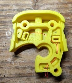
I wanted to create an invisible filament sensor inside the toolhead to check if the filament runs out or if there is a clog in the extruder gears. Tested on Dragon normal flow, not tested on Dragonfly, but it should work. https://github.com/diego589/Mini-AB-Filament-Sensor/raw/main/Images/Comparison.jpeg BOM For both (before and after the extruder's gears) 2x digital hall sensor, it doesn't matter if it's latching or not. I'm using U18 7x 4mm ball bearings 4x 5mm x 3mm Round Neodymium Magnets 2x 10k ohm resistor Thin wires, 32 AWG recommended BOM If you only want a sensor before the gears: 1x Digital hall sensor 1x ball bearing 2x Magnets 1x resistor Thin wires BOM If you only want a sensor after the gears: 1x Digital hall sensor 6x ball bearings 2x Magnets 1x resistor Thin wires Tools Multimeter Printed parts [a]FS_Mid_Body.stl - Needed Recommended to print 2 copies of every hall sensor holder [a]FS_Cowling_Dragon.stl - Not needed at all, but print it if you don't want to sand it down (step 13) Assembly Insert 6 balls in 1 Insert magnet in 1 Make sure that magnet is around 2mm down the tunnel, if not, then push it using filament or something similar Test your clearances by inserting filament, when there is no filament the magnet should be 2mm down the tunnel and when the filament is loaded, the magnet should raise up about 2mm Insert a magnet in 3, it should repel the magnet in 1. If you inserted it in the wrong orientation use an 1.5 or 2mm drill bit to remove it out of the hole Prepare hall sensor, solder resistor at no less than 10 cm from the sensor Test your circuit, move the hall sensor towards each magnets and check with a multimeter between GND and OUT, it should read 5v next to one and 0v next to the other Insert the hall sensor in [a]HallSensorHolder145-145.stl, then insert the holder with the sensor in 2 (small face of sensor pointing towards 3). DO NOT force it yet Load and unload filament and check with a multimeter if there is any variation, if the voltage doesn't change, rotate hall sensor and repeat If everything is working, push the hallsensor holder in place If it's not working, remove it and try with a different sensor holder, then repeat For the sensor that goes before the gears follow the same instructions but use just 1 ball bearing instead Bend the sensor pins until they are below the highlighted part (image below) Route your cable following the path as shown in the image below. If you didn't print [a]FS_Cowling_Dragon.stl you have to sand a path down yourself (black circle in image below) Choose any available pin on your board. In this case I am using RX2 and TX2 because they are right next to GND and +5v. See TestCode.txt-
- 4
-

-
- diego589
- filament sensor
- (and 2 more)