


About This File
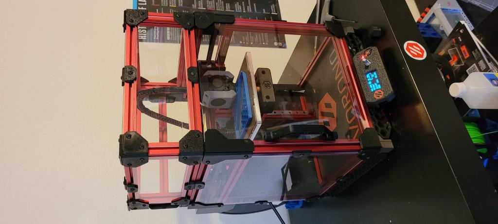
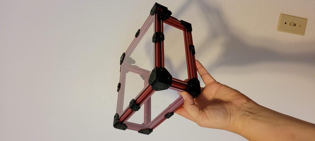
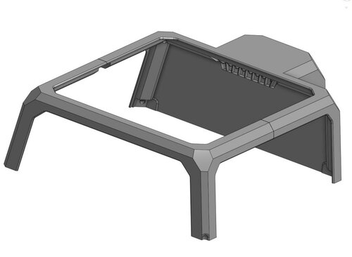
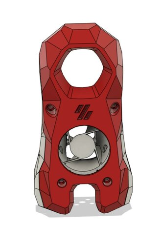
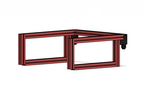
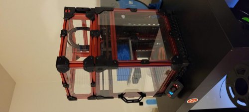
Hinged Hat for the V0
This is my new design for a fold away hinged top hat for the V0, i have included the step file for all the parts i designed, as well as added a BOM for everything you need to get in order to build this,
assembling is pretty straight forward i have added the steps i took when assembling it in picture form here
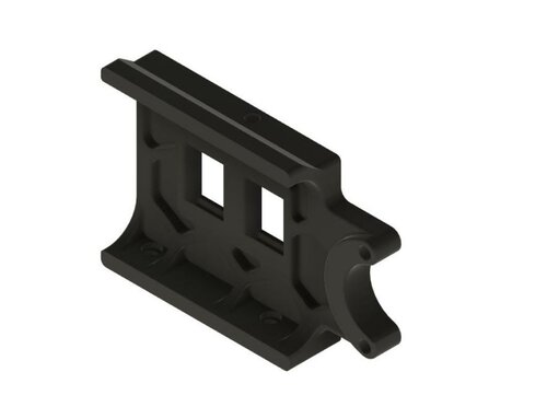
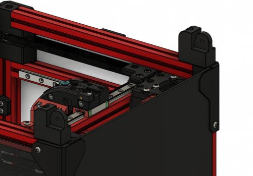
Step 1

NOTE: This step uses M3x12 screws
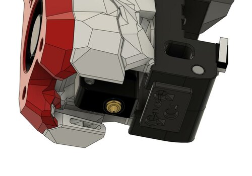
Is to attach the bottom hinge pieces to the top of the V0 first with the little pegs on the bottom of the bottom hinges going into the holes on the A and B drive parts on top of the V0 using M3x12 screws
Step 2

NOTE: This step uses M3x16 screws
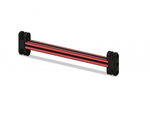
attach the 200mm extrsusion to the printed parts
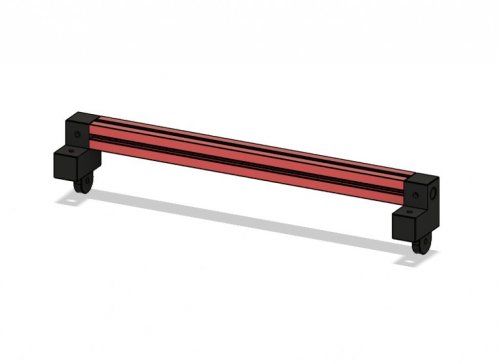
Step 3

NOTE: This step uses M3x8 screws
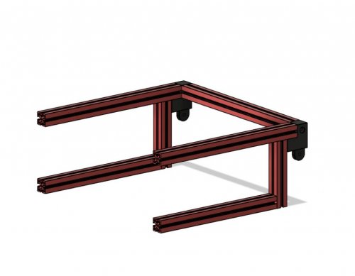
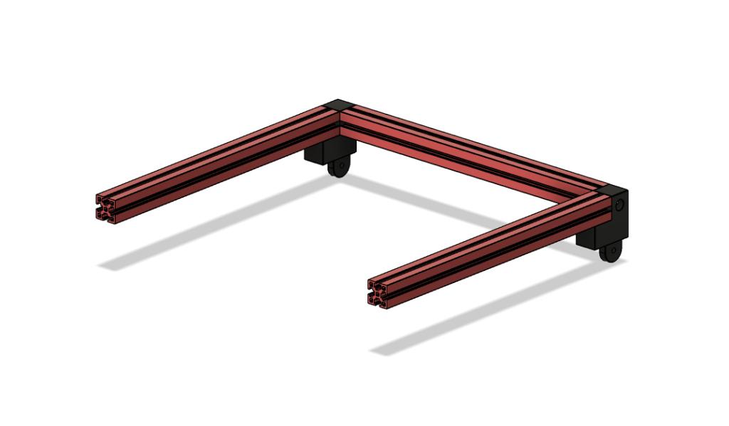
next is the rear frame for the top hinge assembly, attach the two top hinge pieces to a 200mm extrusion as shown, be aware that these pieces are mirrors of eachother and it matters which side they go on, they are attached using m3x8 screws
Step 4
NOTE: This step uses M3x8 screws
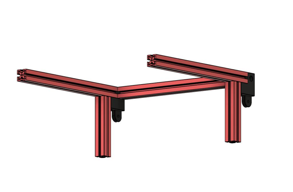
next is to add these 200mm extrusions to the top hinge assembly created in previous step, these also use m3x8 screws
Step 5
NOTE: This step uses M3x8 screws
attach the 2 80mm extrusions up against the top hinge assembly
Step 6

NOTE: This step uses M3x8 screws
attach the 170mm extrusions that go up against the 80mm extrusions
Step 7
NOTE: This step uses M3x8 screws
now add the 92mm extrusions to the front of the frame, now these are 92mm long but the gap between the top and bottom extrusion is 95mm, you want the top of the extrusion to be flush and leave a little gap in the bottom of them which is for the alignment pins
Step 8

NOTE: This step uses M3x8 screws
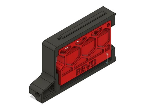
these are the alignment pins, they are used to register in the holes on top of the front idlers on the V0 and they just attach to the bottom of the 92mm extrusions
Step 9
NOTE: This step uses M3x8 screws
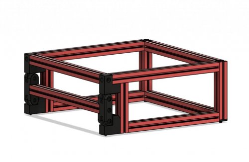
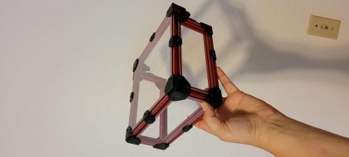
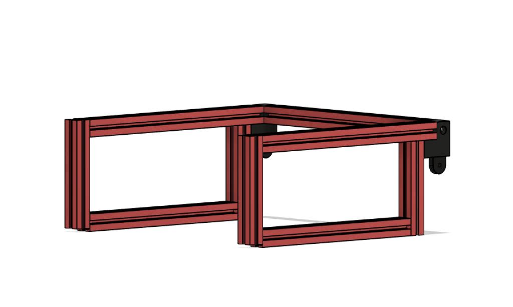
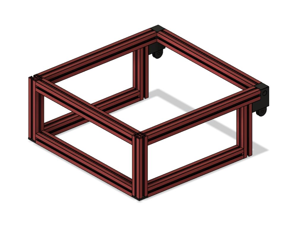
attach the 2 front extrusion and you should have the completed frame now
Step 10
NOTE: This step uses M3x20 screws
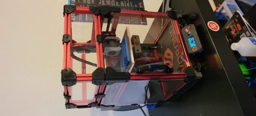
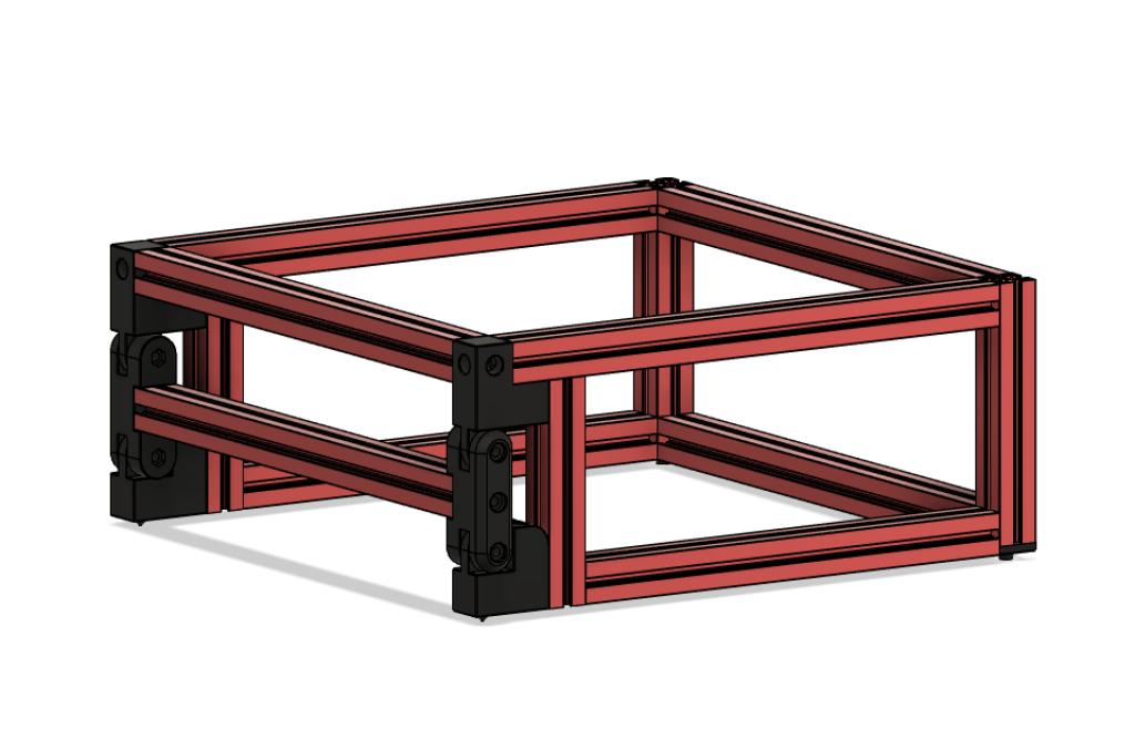
what I would do next is attach the bottom hinge and top hinge together using the middle hinge assembly you made in step 2 and check to make sure every thing is moving correctly and lining up properly, and make any adjustments you see fit.
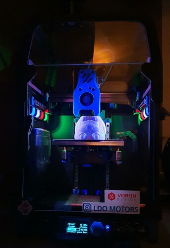
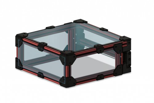
final step

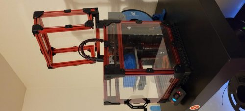
Once the frame is moving correctly and everything is working well together, add the panels to the top hat to enclose it completely there are 2 panels that go in the back the inner one can be left out, I originally didn't have the final rear printed panel but now that it's there , the inner rear panel is no longer needed
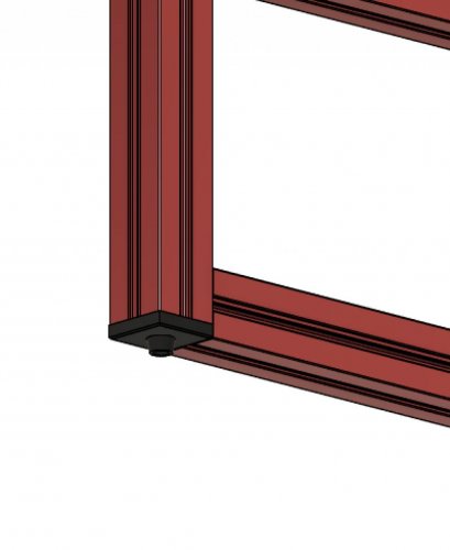
Screw size and locations
bottom hinge uses m3x12 to attach to the frame using an m3 nut that needs to be slid into the top extrusion of the V0, I did this by unscrewing the front of it from the idler bracket and just dropping a nut in the extrusion
top hinge which also uses an m3x12 and m3 nut in 1 of the 3 holes to attach it to the bottom of the top extrusion of the hat frame the other 2 are m3x8 and are screwed into the ends of the extrusions
the middle hinge (middle screw) is an m3x16 and it screws into the end of the middle extrusion
the middle hinge (2 outer screws are m3x20) they screw into embedded nuts on the back of the middle hinge piece
i hope the pictures help with assembly they are named in the correct order to assemble it
when it comes to drilling the holes in the extrusions to screw them together, there is a drilling guide stl in the stl folder and it has 3 holes, the one closest to the end is for the 92mm extrusions on the bottom of them, the same end that the alignment pin stl gets screws on. the middle hole in the driling guide is just a standard 7.5mm from the edge to make normal blind joints you did with the v0 and the highest hole is to attach the 80mm extrusion to the top 200mm extrusion (you drill the hole in 200mm extrusion)
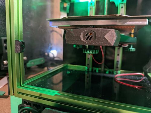
i found it easier to assemble it from the back of the top hat forward. if you open the step file you can see how it assembles. i have tested this quite a bit and so far its been working great! please feel free to make any modifications to it as you see fit
i hope you enjoy it
-hartk1213 V0.108
BOM
1515 Extrusions
| Length (mm) | Qty | Misumi Part Number |
|---|---|---|
| 200 | 5 | HFS3-1515-200 |
| 170 | 2 | HFS3-1515-170 |
| 92 | 2 | HFS3-1515-92 |
| 80 | 2 | HFS3-1515-80 |
| Enclosure Panels Location |
Dimensions | Qty |
|---|---|---|
| Front | 212x76 | 1 |
| Sides | 182x76 | 2 |
| Top | 212x212 | 1 |
| Rear | 212x59 | 1 |
| Screws Size |
Qty |
|---|---|
| M3x8 | 68 |
| M3x12 | 4 |
| M3x16 | 2 |
| M3x20 | 4 |
| M3 Nuts | 64 |
Pictures