Jump to content

MGN 12 Y rail mod for Trident gantry v. 1.0.3

   (0 reviews)

2 Screenshots

  • Like 10
  • Voron FTW! 1
  • Thanks 1

Recommended Comments


Any chance you can update the endstop PCB bracket to fit the MGN12 mounting holes instead of the MGN9 as well?  This is a nice update just not as handy without the endstop bracket being able to fit as well.

  • Like 1
Link to comment
Share on other sites
7 hours ago, fury3d said:

Any chance you can update the endstop PCB bracket

I updated both the Hall Effect and micro switch version. I did have to shift the mounting holes on the Magnetic Y bump stop over 1.56mm to get the sensor to line up with the magnet. Let me know how it works out. 

Link to comment
Share on other sites

If you want we could possibly collaborate together.

I’ve also been working on brackets that not only allow us to utilize 2040 and even 4040 extrusion for the frame but also enables 9mm-12mm wide GT2 belt. 
 

for larger printers an absolute must.

the think the PCB endstop just needs to be modded ever so slightly for the two mounting holes to line up.

Edited by fury3d
  • Like 1
Link to comment
Share on other sites

I'll take a look. Direct modeling is great but easy to let small mistakes slip though. 

Im working on squeezing a Trident into an old MakerBot rep2 right now. Great first Voron project haha.


Happy to help you out. The edits are pretty easy in Fusion. It's more deleting chamfers and fillets to get to model to behave then recreating them. 

Edited by Ducky4546
Link to comment
Share on other sites

I’ve already successfully got it so we can easily trident both the Ender5 and Ender6 but having the MGN12 and even MGN15 options for the rail is awesome.

inthink MGN12 is the max we can do on the x-carriage since since the spacing for using the stealthburner mounts is really tight to get anything beyond 9-12mm belt in place.  

  • Like 1
Link to comment
Share on other sites
On 12/19/2022 at 5:31 PM, fury3d said:

PCB endstop just needs to be modded ever so slightly for the two mounting holes to line up.

I found the error! 

I had a strange STL generation error in Fusion 360. I tried a new "Make+" plug in where it would let me alter the orientation while doing the STL setup. I thought great! But it turns out that I generated files that were incorrect. The end stop file were the only part I made with the new Make+ plugin.

Anyway I recreated the limit switch STL files and it all looks good now in the slicer. Good catch @fury3d

    Tim 


Link to comment
Share on other sites

I thought I was going crazy at first myself so you weren't alone!

Very very solid upgrade.  If anyone is curious I can also upload files for using 2040 extrusion for your voron as the 2020 frame is VERY VERY VERY limited.  I wouldn't recommend it for the 300-350mm machine.  Great to see more parts like this.


  • Like 1
Link to comment
Share on other sites

got her all working tonight.  

Full 2040 T-slot Extrusion Frame

MGN12H linear rail on X Y and Z axis DONE!  

I dont think people can imagine it but the trident is truly a god mode printer.

  • Voron FTW! 1
Link to comment
Share on other sites

Hi there - great idea, but I found an issue. The MGN12H carriage is 2mm taller than the MGN9H carriage, but the model isn't altered to compensate for that. This results in the bearing stacks sitting too low and causing the belts to no longer be parallel.

Should be relatively easy to fix the model. If like me one doesn't realize this issue until after putting things together, one can add two 1mm shims at the lower end of both bearing stacks to get things back into alignment. 

  • Like 1
Link to comment
Share on other sites

@terranx thanks for catching this. I didn't think about the height difference between the bearing trucks.

Im just about to run the belts in my build and would have been scratching my head for sure. I'll get the models updated later today. 

Link to comment
Share on other sites

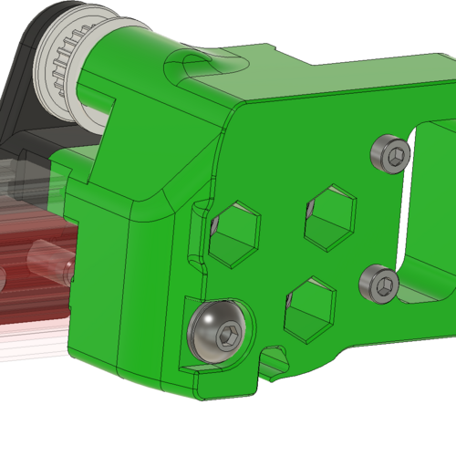
I've got the alignment oversight corrected on the left XY Joint. The MGN 9 to 12 had a 3mm difference in height! I moved the mating face for the MGN-12 truck down 3mm as well as the lower face which sits on the print bed. 

All the pulleys line up now👍

All the stock hardware is unaffected. The hex pockets are now 3mm deeper and I added an extended counterbore for the 5x30mm button head (Avoiding excessively thin walls.) 

Some of the .STL files have had support helpers modeled in. Most have a .2 layer vertical separation. My question is how much wall offset should I use . Any other suggestions are welcome. I will get the opposing side corrected after I sort out what mods to the limit switches are in order. 


2135724129_pulleyslineup.thumb.png.8fa17d16478b34037c25e130fc116aae.png

1829269366_MGn12nohardwarechange.thumb.png.2330cb111b7e097f3c008d4e82badc8b.png

1295780805_MGN12ModPrintHelper.thumb.png.b0495b436f5fcd55424549b83ca414bc.png

MGN12 mod 1.png

Link to comment
Share on other sites

You're right, it's 3mm -- 2 from the truck, 1 from the rail, I wasn't taking the MGN12 rail itself into account. 

Another thing that occurred to me is that the truck is also 7mm wider than the MGN9 piece, so there either needs to be some adjustment to pull the whole assembly inward 3.5mm or the aluminum extrusion itself needs to be made 7mm shorter (3.5mm for each side) to get the geometry to line up as intended. I did end up modeling a variant myself to account for all that. There is enough play in the gantry that you can force things to mount without that adjustment, but I imagine that would put some parts under stress. I didn't personally bother making the endstop pod etc since I'm runnign CAN-bus with an umbilical and relocated the endstops for that anyway. 

I'm on a 2.4 for what it's worth, but these pieces (with the exception of the magnet holder for the hall effect endstop) are the same between the two printers. 

Link to comment
Share on other sites

Yes the MGN 12 truck does stick out last the frame perimeter a little bit. I'm not sure how I would slide the linear rail inboard unless I had a cross beam with the ability to mount off center?

My build I'm working on started as a Trident gantry and has evolved into this 200x300x200mm Frankenstein. My plan was to just space off the side panels. 

Im also looking into an Umbilical setup or Can to cut down on wiring complexity.IMG_20230208_145125_094.thumb.jpg.00b3eb499a1884ccec1987419d287bc3.jpg

Link to comment
Share on other sites
36 minutes ago, Ducky4546 said:

Im also looking into an Umbilical setup or Can to cut down on wiring complexity.

Seems the way to go.

Build coming along nicely

  • Like 1
Link to comment
Share on other sites
4 hours ago, Ducky4546 said:

Yes the MGN 12 truck does stick out last the frame perimeter a little bit. I'm not sure how I would slide the linear rail inboard unless I had a cross beam with the ability to mount off center?


No that's not what I'm getting at. The MGN12 truck is going to stick out no matter what since it's wider than the extrusion. 


The point I was trying to make is that in the model as it exists right now, the extra width (7mm) is added entirely at the outside. So that results in the centerline of the MGN mount being pushed out by 3.5mm on each side.

I don't have the CADs for your models so it's hard to demonstrate, but here's some STLs lined up in a slicer in an attempt to show what I mean


image.thumb.png.58d3fd9d032eec91d151d9b671f72708.png

Top is stock MGN9 piece

Middle is your MGN12 piece

Botton is an MGN12 variant I cooked up earlier today


I tried to align them such that the holes for the pulleys etc are all lined up. You'll notice the center of your MGN mount is shifted outwards. Overall dimensions are going to be larger no matter what, theres no question about that. But ideally the center of the trucks whether MGN9 or MGN12 would be lined up. 

Link to comment
Share on other sites

@terranx You are right on the money. The offset I made for the trucks pushed all the belt idlers in board (3.891mm). Thanks for highlighting that. I was getting a bit cross eyed looking at this thing too long.

So it seems I have a bit more CAD work to do. The good news is I can gain almost 4mm on each side of the X travel for things like a nozzle brush, clicky probe maybe a purge shoot. Part of me says I should have just stayed with the MGN 9 but we are in too deep to turn back now. 

Having other smart people to work with and bounce things off is what makes this project fun! 

200x300 MGN 12 :

1224221528_200x300beltoffset.JPG.cd0c38f2026d2febf1d99f29155014f7.JPG


Stock Trident :

1247786229_StockTridentbeltpath.thumb.JPG.f5b84084c8048c4e7156301e475ec6d3.JPG

Link to comment
Share on other sites

I was able to move the pulleys over 3.891mm. Now the primary pulleys are in line with their appropriate AB motor pulley. I added a small relief to make the MGN 12 fit with new new position of the pulley cluster. Everything should be lined up correctly now.

  Fusion direct modeling is powerful but boy was the assembly constraint management driving me up the wall. 

I will print these our and confirm everything works. 

1832123533_ABMotoraligment.thumb.JPG.d70ca6e78fcd58587431c8ead495ea12.JPG


1625784923_3.981RightOffset.thumb.JPG.3f0465b2a8df2d238fa637d5868f3dc8.JPG249583675_3.981LeftOffset.JPG.3053d23b21e60e0dba6c0f97c5754dc3.JPG

200x300 belt offset.JPG

Stock Trident belt path.JPG

Edited by Ducky4546
Link to comment
Share on other sites

Printed test parts with the correct offset work! Everything lines up and my printer has belts for the first time. I just need to make one small edit to the wall chamfer to give a little more room for perimeters near one of the hex nuts. PXL_20230216_153656347.thumb.jpg.b935d350b44b49ec292c2764f39b3993.jpgPXL_20230216_153643547.thumb.jpg.74bc90252117b0a5762e9b0d4c597638.jpgPXL_20230216_162143785.thumb.jpg.df30772c0dfaa021bd53200f81647d17.jpgPXL_20230216_162154891.thumb.jpg.2d71d821fbbdac16d6f6b7c8fcb70a65.jpg


  • Like 2
Link to comment
Share on other sites

Will the new changes be uploaded? Had issues with an earlier version that looks to have been corrected.

Link to comment
Share on other sites

I added a bump out this morning and fixed some artifacts from the direct modeling mods. I am printing out another set just to verify I didn't mess anything else up. I will upload a new version later today. 

Below shows the thin wall I needed to fix before I was away on vacation :

1727465531_MGN12thinwall.thumb.png.ce41edcbffead61294c51581e54a75cc.png

: These are what the corrected parts look like :1488641485_MGN12modthinfixright.thumb.png.9d9f8c77bddb95219e1ce4be8930bf30.png

479983890_MGN12thinfixleft.thumb.png.04f535236fee66d3387b78645fd4222d.png

Bump out allows for clean perimeters around the outer most hex pocket :

1629650242_Thinwallissue.JPG.52d9a474fbb1c84a53a3a672bfb2850f.JPG

  • Like 1
  • Thanks 1
Link to comment
Share on other sites
39 minutes ago, arlotami said:

Where can I find the stl for the limit switch mounts?

I will work rework those limit switch mounts. My previous version had them but since everything has moved to correct the belt alignment I did not include them in this version. 

Link to comment
Share on other sites

Join the conversation

You can post now and register later. If you have an account, sign in now to post with your account.

Guest
Add a comment...

×   Pasted as rich text.   Paste as plain text instead

  Only 75 emoji are allowed.

×   Your link has been automatically embedded.   Display as a link instead

×   Your previous content has been restored.   Clear editor

×   You cannot paste images directly. Upload or insert images from URL.

 Share


User Feedback

×
×
  • Create New...