


23 14 2 Details Changelog 0 Questions 686 Comments 3 Reviews 1 Tutorial Support Recommended Comments Prev 23 24 25 26 27 28 Next Page 28 of 28 Beardo3D 2 Posted June 27 Share Ok, just pulled a sample print off the bed and installed a camera. Is it just me or is the camera facing away from the nozzle....lol Quote Link to comment Share on other sites More sharing options... atrushing 1,070 Posted June 27 Share 2 hours ago, Beardo3D said: Ok, just pulled a sample print off the bed and installed a camera. Is it just me or is the camera facing away from the nozzle....lol I don't know why that hole is on the front side of the shroud. It was in the Stealthburner geometry that I borrowed. The camera module should fit the other way around as well. Quote Link to comment Share on other sites More sharing options... Beardo3D 2 Posted June 27 (edited) Share Ahhhhh...that makes complete sense. I think the hole just got me thinking down the wrong path. Thanks for point that out! Edited June 27 by Beardo3D Quote Link to comment Share on other sites More sharing options... loudneon 0 Posted June 28 Share I’ve printed the V2 of the mini stealthburner for my Ender 3 pro. I had to modify the carriage to be compatible with my set up. I’ve run into an issue where I don’t have good access to a good x endstop. Does anyone have any suggestions? Thank you Quote Link to comment Share on other sites More sharing options... atrushing 1,070 Posted June 28 Share 6 hours ago, loudneon said: I’ve printed the V2 of the mini stealthburner for my Ender 3 pro. I had to modify the carriage to be compatible with my set up. I’ve run into an issue where I don’t have good access to a good x endstop. Does anyone have any suggestions? Thank you I've tried to mock up your setup. It seems to be a decent location for the X endstop. What problem are you having? Quote Link to comment Share on other sites More sharing options... loudneon 0 Posted June 28 Share 3 hours ago, atrushing said: I've tried to mock up your setup. It seems to be a decent location for the X endstop. What problem are you having? My EBB36 board is hitting the inside of my z rails before the carriage can hit the x endstop. I did not see any files for a x endstop that can be mounted to the side of the tool head or an extension to make contact with my current endstop location. The picture I’ve attached is as far as my carriage can go before my EBB36 hits my inside z extrusion. Quote Link to comment Share on other sites More sharing options... atrushing 1,070 Posted June 28 Share 7 hours ago, loudneon said: My EBB36 board is hitting the inside of my z rails before the carriage can hit the x endstop. I did not see any files for a x endstop that can be mounted to the side of the tool head or an extension to make contact with my current endstop location. The picture I’ve attached is as far as my carriage can go before my EBB36 hits my inside z extrusion. Would you be able to add a hole in the side of the x-carriage for an M3 screw? Then you could even adjust the trigger distance. I have also used the other hole that you can see in the core piece with a heat set insert to add a spacer for sensorless homing but I don't think it would line up for your printer. Quote Link to comment Share on other sites More sharing options... loudneon 0 Posted June 28 Share 1 hour ago, atrushing said: Would you be able to add a hole in the side of the x-carriage for an M3 screw? Then you could even adjust the trigger distance. I have also used the other hole that you can see in the core piece with a heat set insert to add a spacer for sensorless homing but I don't think it would line up for your printer. Yes I would be able to add the screw thank you. Quote Link to comment Share on other sites More sharing options... Beardo3D 2 Posted 15 hours ago (edited) Share Ok. I'm back. Had a major catastrophic failure. Had a multimeter probe slipped and sent 24v through a 5v leg. Smoked my m8p, cm4, NH hexa and bme280. Unfortunately, I had no backups of my configs. Got most of the boards replaced, the bme280 delivers today. But over all, the printer is about ready again for a test print. I plan on printing all new mini stealth cowls to include the nozzle cameras. Think I should be able to start that today. Question for you. Ever thought about modifying the docks to have the heads held in by magnets? Having some serious difficulty with the heads staying put with the umbilicals pushing them off. Looking for a better solution. Also, did the cover piece of the cowlings get modified to fit the orbiter better? Pointed that out in an earlier post about it conflicting with the upper most plug on the back of the filament sensor. Thanks for the work you have done! Edited 13 hours ago by Beardo3D Quote Link to comment Share on other sites More sharing options... atrushing 1,070 Posted 8 hours ago Share 7 hours ago, Beardo3D said: Ok. I'm back. Had a major catastrophic failure. Had a multimeter probe slipped and sent 24v through a 5v leg. Smoked my m8p, cm4, NH hexa and bme280. Unfortunately, I had no backups of my configs. Got most of the boards replaced, the bme280 delivers today. But over all, the printer is about ready again for a test print. I plan on printing all new mini stealth cowls to include the nozzle cameras. Think I should be able to start that today. Question for you. Ever thought about modifying the docks to have the heads held in by magnets? Having some serious difficulty with the heads staying put with the umbilicals pushing them off. Looking for a better solution. Also, did the cover piece of the cowlings get modified to fit the orbiter better? Pointed that out in an earlier post about it conflicting with the upper most plug on the back of the filament sensor. Thanks for the work you have done! Sorry to hear about the fried board. Regarding the magnets, the shroud and core have pockets for 3x6mm magnets to help hold them together. I just use whatever magnets I can get off of Amazon and they aren't very strong but you could get higher quality magnets if needed. I got a bit distracted with other projects and haven't looked at the filament sensor clearance yet. I will take a look at it tomorrow. Quote Link to comment Share on other sites More sharing options... Beardo3D 2 Posted 6 hours ago Share Ok. No hurry. I can do everything I need to with those on. More for cosmetic. Ill dink around with magnets ad soon as I get new board to work! Pretty much same config files but now im getting 'unable to write tmc spin alarms no matter what stepper I buzz now Banging my head. But thanks for letting me know. Quote Link to comment Share on other sites More sharing options... Prev 23 24 25 26 27 28 Next Page 28 of 28 Join the conversation You can post now and register later. If you have an account, sign in now to post with your account. Add a comment... × Pasted as rich text. Paste as plain text instead Only 75 emoji are allowed. × Your link has been automatically embedded. Display as a link instead × Your previous content has been restored. Clear editor × You cannot paste images directly. Upload or insert images from URL. × Desktop Tablet Phone Submit Comment
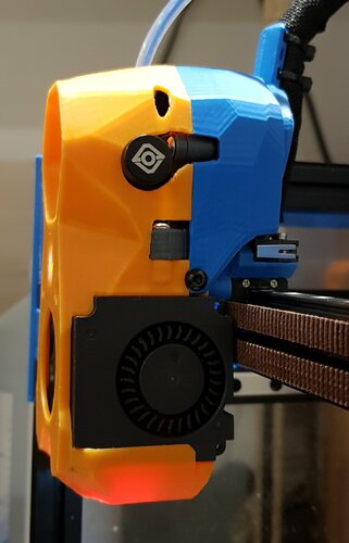
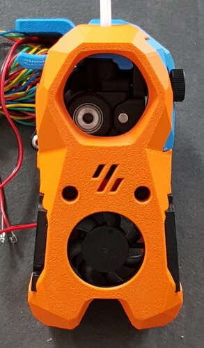
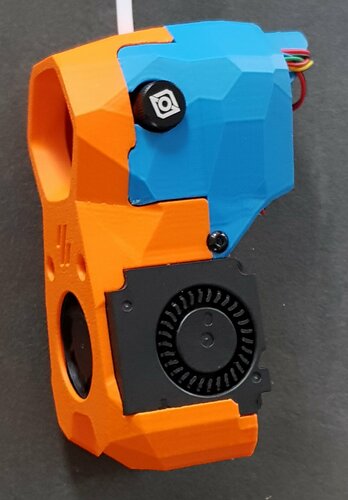
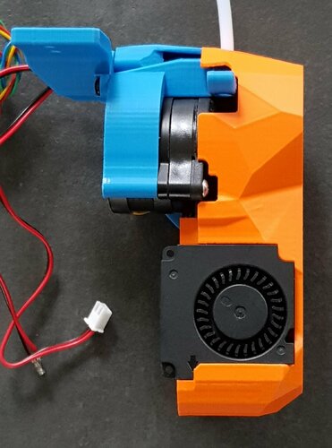
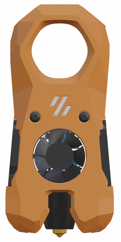
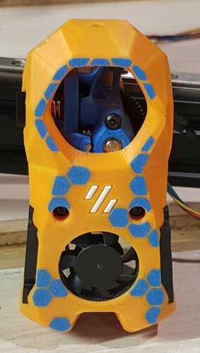
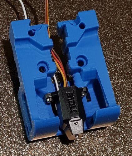
Beardo3D 2 Posted June 27 Share Ok, just pulled a sample print off the bed and installed a camera. Is it just me or is the camera facing away from the nozzle....lol Quote Link to comment Share on other sites More sharing options...
atrushing 1,070 Posted June 27 Share 2 hours ago, Beardo3D said: Ok, just pulled a sample print off the bed and installed a camera. Is it just me or is the camera facing away from the nozzle....lol I don't know why that hole is on the front side of the shroud. It was in the Stealthburner geometry that I borrowed. The camera module should fit the other way around as well. Quote Link to comment Share on other sites More sharing options...
Beardo3D 2 Posted June 27 (edited) Share Ahhhhh...that makes complete sense. I think the hole just got me thinking down the wrong path. Thanks for point that out! Edited June 27 by Beardo3D Quote Link to comment Share on other sites More sharing options...
loudneon 0 Posted June 28 Share I’ve printed the V2 of the mini stealthburner for my Ender 3 pro. I had to modify the carriage to be compatible with my set up. I’ve run into an issue where I don’t have good access to a good x endstop. Does anyone have any suggestions? Thank you Quote Link to comment Share on other sites More sharing options...
atrushing 1,070 Posted June 28 Share 6 hours ago, loudneon said: I’ve printed the V2 of the mini stealthburner for my Ender 3 pro. I had to modify the carriage to be compatible with my set up. I’ve run into an issue where I don’t have good access to a good x endstop. Does anyone have any suggestions? Thank you I've tried to mock up your setup. It seems to be a decent location for the X endstop. What problem are you having? Quote Link to comment Share on other sites More sharing options...
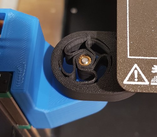
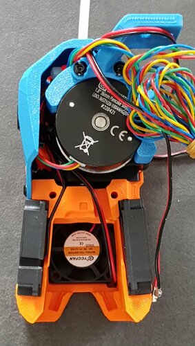
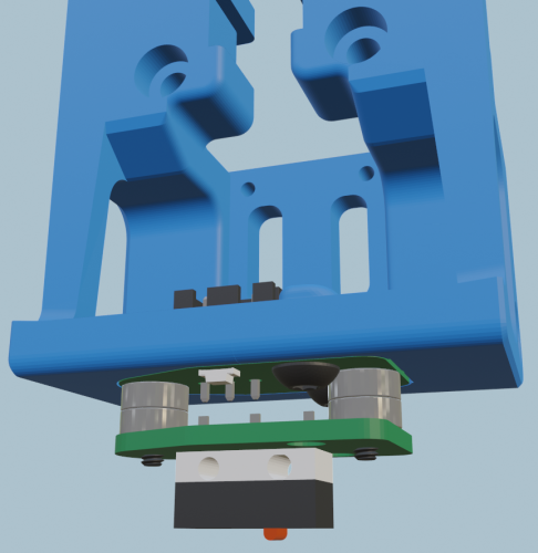
loudneon 0 Posted June 28 Share 3 hours ago, atrushing said: I've tried to mock up your setup. It seems to be a decent location for the X endstop. What problem are you having? My EBB36 board is hitting the inside of my z rails before the carriage can hit the x endstop. I did not see any files for a x endstop that can be mounted to the side of the tool head or an extension to make contact with my current endstop location. The picture I’ve attached is as far as my carriage can go before my EBB36 hits my inside z extrusion. Quote Link to comment Share on other sites More sharing options...
atrushing 1,070 Posted June 28 Share 7 hours ago, loudneon said: My EBB36 board is hitting the inside of my z rails before the carriage can hit the x endstop. I did not see any files for a x endstop that can be mounted to the side of the tool head or an extension to make contact with my current endstop location. The picture I’ve attached is as far as my carriage can go before my EBB36 hits my inside z extrusion. Would you be able to add a hole in the side of the x-carriage for an M3 screw? Then you could even adjust the trigger distance. I have also used the other hole that you can see in the core piece with a heat set insert to add a spacer for sensorless homing but I don't think it would line up for your printer. Quote Link to comment Share on other sites More sharing options...
loudneon 0 Posted June 28 Share 1 hour ago, atrushing said: Would you be able to add a hole in the side of the x-carriage for an M3 screw? Then you could even adjust the trigger distance. I have also used the other hole that you can see in the core piece with a heat set insert to add a spacer for sensorless homing but I don't think it would line up for your printer. Yes I would be able to add the screw thank you. Quote Link to comment Share on other sites More sharing options...
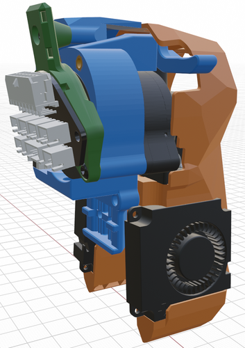
Beardo3D 2 Posted 15 hours ago (edited) Share Ok. I'm back. Had a major catastrophic failure. Had a multimeter probe slipped and sent 24v through a 5v leg. Smoked my m8p, cm4, NH hexa and bme280. Unfortunately, I had no backups of my configs. Got most of the boards replaced, the bme280 delivers today. But over all, the printer is about ready again for a test print. I plan on printing all new mini stealth cowls to include the nozzle cameras. Think I should be able to start that today. Question for you. Ever thought about modifying the docks to have the heads held in by magnets? Having some serious difficulty with the heads staying put with the umbilicals pushing them off. Looking for a better solution. Also, did the cover piece of the cowlings get modified to fit the orbiter better? Pointed that out in an earlier post about it conflicting with the upper most plug on the back of the filament sensor. Thanks for the work you have done! Edited 13 hours ago by Beardo3D Quote Link to comment Share on other sites More sharing options...
atrushing 1,070 Posted 8 hours ago Share 7 hours ago, Beardo3D said: Ok. I'm back. Had a major catastrophic failure. Had a multimeter probe slipped and sent 24v through a 5v leg. Smoked my m8p, cm4, NH hexa and bme280. Unfortunately, I had no backups of my configs. Got most of the boards replaced, the bme280 delivers today. But over all, the printer is about ready again for a test print. I plan on printing all new mini stealth cowls to include the nozzle cameras. Think I should be able to start that today. Question for you. Ever thought about modifying the docks to have the heads held in by magnets? Having some serious difficulty with the heads staying put with the umbilicals pushing them off. Looking for a better solution. Also, did the cover piece of the cowlings get modified to fit the orbiter better? Pointed that out in an earlier post about it conflicting with the upper most plug on the back of the filament sensor. Thanks for the work you have done! Sorry to hear about the fried board. Regarding the magnets, the shroud and core have pockets for 3x6mm magnets to help hold them together. I just use whatever magnets I can get off of Amazon and they aren't very strong but you could get higher quality magnets if needed. I got a bit distracted with other projects and haven't looked at the filament sensor clearance yet. I will take a look at it tomorrow. Quote Link to comment Share on other sites More sharing options...
Beardo3D 2 Posted 6 hours ago Share Ok. No hurry. I can do everything I need to with those on. More for cosmetic. Ill dink around with magnets ad soon as I get new board to work! Pretty much same config files but now im getting 'unable to write tmc spin alarms no matter what stepper I buzz now Banging my head. But thanks for letting me know. Quote Link to comment Share on other sites More sharing options...
Recommended Comments
Join the conversation
You can post now and register later. If you have an account, sign in now to post with your account.