-
 36
36
-
 5
5
-
 3
3
What's New in Version 1.0.0 See changelog
Released
About This File
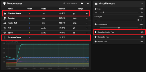
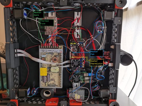
I was having trouble getting my enclosure temperatures above 45C to achieve my optimum print settings. This is the solution I came up with to solve my enclosure temperature issues. I'm running a Fystec Spider v1.1, so your printer config would likely differ. I'm also using a Hartk v4.0 PCB that has an integrated chamber thermistor. I've included my settings for this as well, but you may need to change this up if you use a different thermistor for enclosure temperature readings.
I hope this is helpful for someone. I couldn't find a lot of solutions out on the net that could get me up and going with a setup like this, so it was a lot of trial and error to get to this point. Let me know if you have any comments or suggestions that can help me make this thing better!
How I set things up:
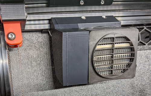
- I removed the fan from the PTC heater and inserted a 100K NTC thermistor into one of the bordering fins on the heater core. I then filled the remaining gap in the fin with thermal grease and reattached the fan.
- I added a thermal fuse to make sure the power would get cut if the temperatures get out of hand from a bad config or faulty piece of hardware. First I drilled a 1/8" hole next to the center ground pin, rivetted the fuse to the heater's core, and applied thermal grease between the fuse body and the heater core. I then moved the ground wire to run from the fuse rather than the tab. Once I wired this up, I ran the temperatures up past the fuse limits to verify things fail safely as expected.
- I extended all of the wiring with solder connections to make sure it would be long enough reach each wire's intended destination, and capped each connection with heat shrink.
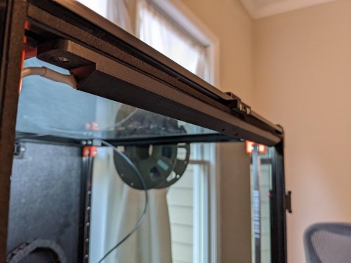
- I mounted the PTC heater to the printed PTC heater mount and ran the wires to the wiring compartment.
- I installed the Omron relay, and ran a 24v output from my controller to the relay's 5-24v input. I then routed 110v AC to the other end of the relay on the hot lead.
- I finished up the wiring by hooking up the 12v line for the heater fan and the heater thermistor to the controller board. (Note: my chamber thermistor was already installed on my toolhead's PCB)
- I updated my printer.cfg and ran a bunch of tests on the heater to make sure it was functioning properly.
BOM:
Electronics:
- PTC Heater w/ Fan x1 - Item on Amazon
- NTC 100k thermistor - Item on Amazon
- 120C Thermal Fuse - Item on Amazon
- Omron 5-24v Relay - Item on West3D
Printed Parts:
- Printed PTC Heater Mount x1
Miscellaneous:
- M3x8mm SHCS x2
- M3 T-nut x2
- 18awg stranded wire ~2 meters
- 22awg stranded wire ~2 meters
- 1/8" Rivet x1
- Appropriate connectors for you controller board
Changes to printer.cfg:
######################
### Chamber Heater ###
######################

[heater_generic chamber_heater]
heater_pin: PC8
sensor_type: Generic 3950
sensor_pin: PC2
control: watermark
max_power: .5
min_temp: 0
max_temp: 110

[verify_heater chamber_heater]
max_error: 120
check_gain_time: 120
hysteresis: 5
heating_gain: 2

##########################
### Chamber Heater Fan ###
##########################

[heater_fan chamber_heater_fan]
pin: PB6
max_power: 1.0
heater: chamber_heater
heater_temp: 40.0 # fan will turn off below this level

#############################
### Enclosure Temperature ###
#############################

[thermistor chamber_thermistor]
temperature1: 25
resistance1: 10000
beta: 3950

[temperature_sensor enclosure_temp]
sensor_type: chamber_thermistor
sensor_pin: PC1
min_temp: 0
max_temp: 80