Search the Community
Showing results for tags 'voron 2.4'.
Found 10 results
-

Version 1.0.0
18 downloads
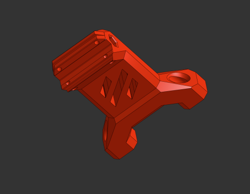
-------------English/Englisch------------- Hey everyone! I whipped up this wall mount for my Voron 2.4 because I was tired of all the vibrations while printing. Plus, it keeps the printer from sliding around at high speeds. So far, it’s been awesome! What It Does: Flexible Use: You can mount it in any orientation. No need to mirror anything in your slicer – just print it 2x or more, depending on how many mounts you need. Cable Pass-Through: A lot of folks hide cables in the aluminum profiles, but that gets tricky when you want to screw something onto them. So, I added a cable slot to this mount – just run the cable through there. (You might need to re-crimp it, though.) Maybe for Other Printers: I made it for the Voron 2.4, but it could work with other printers using 2020 aluminum extrusion, like the Trident. Give it a shot and see! Testing Phase: I’m currently testing it on my Voron 2.4, and it’s making a real difference. Less wobble, the printer stays put, and I think it’s even a bit quieter (since the vibrations go straight into the wall and get “swallowed” there). Print Tips: Filament: I printed mine in ASA (had some leftovers lying around). ABS or PETG should work fine too. PLA might do the job with a few extra wall loops. Layer Height: I went with 0.2 mm – works for me. Infill: I used 40%, but if your printer’s on the heavy side, maybe bump it up a bit. Supports: Shouldn’t need them, except maybe at the wall interface area. If so, just keep Supports on printbed only. The cable slot has some light bridging, but it’s no big deal – you can add support for better quality if you want, but it’s barely necessary. Assembly Tips: After printing, grab 4 rotating T-nuts and 4 M3x10 screws per mount and slide them into the profile. For my setup, I placed the mounts on the left and right at the back, about 25 cm from the top of the printer. Tighten them up properly (with the 4 bolts), then mark the drill holes on the wall (use a center punch or hole marker). Drill the holes into the wall and add anchors. (Depending on your wall type, you might be able to screw straight in.) Thanks to the mount’s shape, you can easily get to all the holes and screws If you want, use the cable slot to run a cable through (like for build chamber lighting, for example). -------------German/Deutsch------------- Hi zusammen! Ich hab diese Wandhalterung für meinen Voron 2.4 gebastelt, weil ich die Schwingungen beim Drucken loswerden wollte. Außerdem hält sie den Drucker fest, damit er bei hohen Geschwindigkeiten nicht verrutscht. Bis jetzt echt top! Was sie kann: Flexibel einsetzbar: Du kannst die Halterung in jeder Orientierung verwenden. Es muss beim Druck also nichts gespiegelt werden. Einfach 2x oder öfter drucken, je nachdem wie viele Halter du benötigst. Kabeldurchlass: Viele Nutzer verstecken Kabel in den Aluminiumprofilen. Das Problem ist dann, dass die Kabel im Weg sind, wenn etwas an die Profile angeschraubt werden soll. Ich habe daher einen Kabeldurchlass mit in die Halterung eingefügt, damit man das Kabel dort einfach durchführen kann. (Möglicherweise muss man es jedoch neu Krimpen. Vielleicht auch für andere: Ich hab die Halterung primär für den Voron 2.4 erstellt, aber sie sollte theoretisch auch bei anderen Druckern mit 2020er Aluminiumprofilen funktionieren, z. B. dem Trident. Einfach mal ausprobieren! Testphase: Ich teste sie gerade an meinem Voron 2.4, und sie macht echt einen Unterschied. Weniger Wackeln, Drucker bleibt stabil und meines Erachtens sogar etwas leiser (da die Schwingungen direkt in die Wand übertragen werden und dort “geschluckt” werden. Druck-Tipps: Filament: ich habe sie in ASA gedruckt (hatte noch ausreichend “Rest” da. ABS oder PETG sollten auch Funktionieren. PLA möglicherweise mit ein paar mehr Wandschleifen auch. Schichthöhe: 0,2 mm hab ich genommen Füllung: Ich habe 40% verwendet, aber bei schwereren Druckern vielleicht mehr reinpacken. Stützen: Sollten nicht notwendig sein (bis auf den Bereich des Wandinterfaces. Wenn, dann nur auf dem Druckbett. Der Kabelschlitz hat so kleines Bridging, dass es nicht notwendig ist. Für Bessere Qualität kann man es natürlich mit Support drucken, aber es sollte wie gesagt nur wenig support notwendig sein. Montage-Tipps: Nach dem Druck dann einfach je Halter 4 rotierende Nutensteine (T-nuts) und 4 M3x10 Schrauben verwenden und in das Profil einführen. In meinem Fall habe ich die Halter links und rechts an der Rückseite positioniert, ca 25cm von der Oberkante des Druckers. Hier die Halter dann richtig Festschrauben (mit den 4 Bolzen) und die Bohrlöcher an die Wand übertragen (Körner oder Bohrloch-Marker) Die Löcher dann in die Wand Bohren und mit Dübeln versehen. (Je nachdem was für eine Wand ihr habt, könnt Ihr jedoch direkt reinschrauben) Durch die Form des Halters kommt man an alle Löcher / Schrauben bequem heran Wer will kann dann auch die Kabelführung verwenden um dort ein Kabel (zum Beispiel für die Beleuchtung des Bauraumes) hindurch zu führen. -
Version 1.0.1
919 downloads
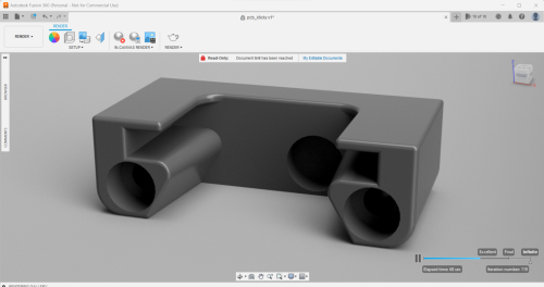
This model is for the PCB Klicky probe available from Fysetc, as featured in the Whopping Voron Mods pack - whopping_Voron_mods/pcb_klicky at main · tanaes/whopping_Voron_mods · GitHub PCB Klicky is based on 2 mods - Klicky Probe by JosAr and Euclid Probe. I really didn't like the original dock that came in the mod pack, I found it to be very fiddly and ineffective for holding the probe. This replaces the dock-front_insert.stl file from the pack. This dock has an enlarged hole on the front to fit the magnet attached to the probe, it also has a space behind big enough to fit a 6x3mm magnet to help hold the probe in place. As well a this, it has tabs on the top to cover the klicky while docking and undocking. This model should be printed upright (as loaded when opened in your slicer) with Voron specs. Tested and working on one of my custom 2.4r2's I went through 2 other iterations of this design before settling on the one that's uploaded; V1 kept to the height of the original dock, however, was slightly too tight all over and didn't have the back magnet mounting. V2 saw an increase in the height of the tabs, allowing for slightly more space to rest the PCB. This proved to be a better fit, but I wasn't happy with the sizing of the front magnet hole - in this iteration I included the back magnet hole. V3 saw an increase in the hole sizing on the front, this enables the probe to dock and undock effortlessly, with no thought. **ADDED 28th JUNE 2023** I have also now made a side mount to attach probe to an adjustable docking station - I use a Volcano hotend and the standard dock isn't long enough, also the side mount doesn't fit the adjustable mount. This enables you to use a longer print head and still use things like the nozzle scrub mod- 16 comments
-
- 12
-

-

-
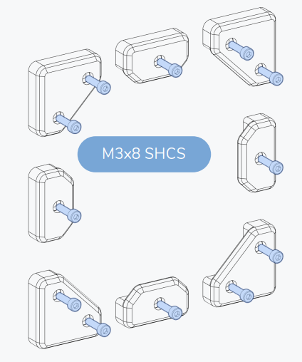
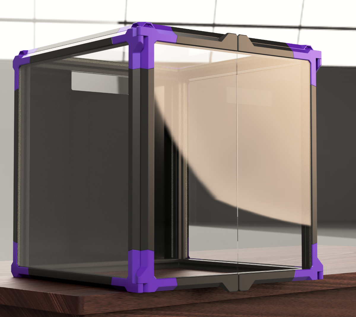
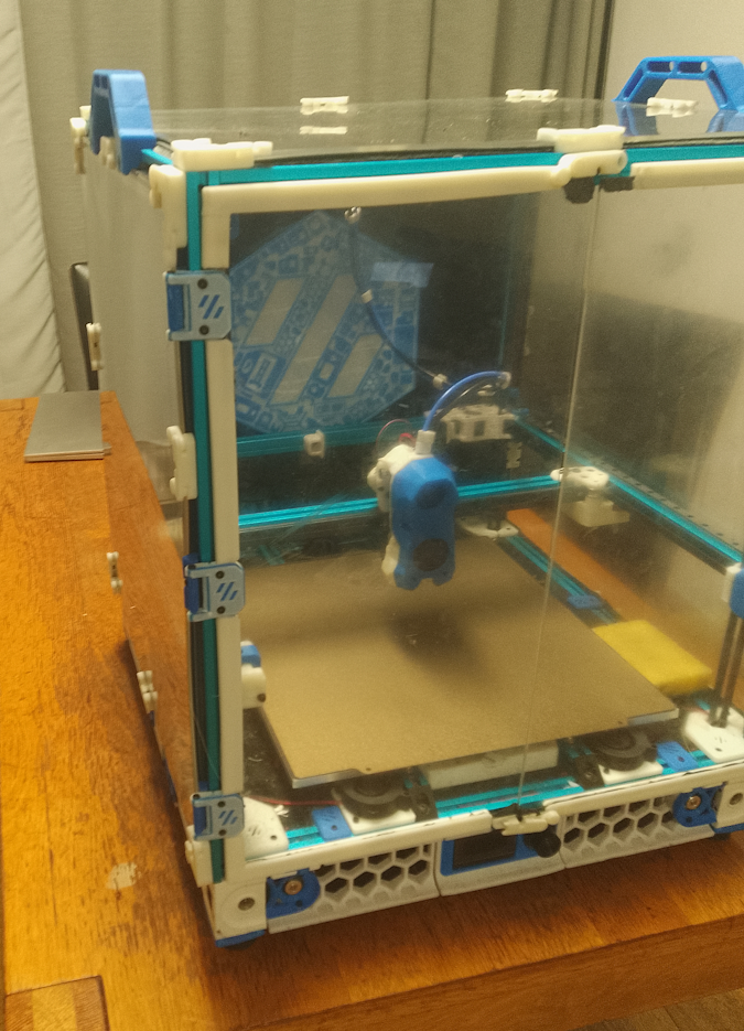
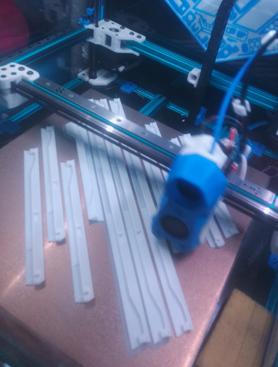
When I got my Fysetc Voron 2.4, 350 kit, almost a year ago, I built it as it was written in the manual: stock. I bravely followed the guide and printed the clips, the print-in-place hinges, used those awful nuts to screw the panels down. Of course the print-in-place hinges were not moving, because I had no idea how to set the tolerances and extrusion multiplier on my Sidewinder X2, so I had to find alternatives. I ran into a post from @Buurman and @mvdveer which was discussing hinges (thank you my fellow Dutchies!) So I used one of those. Getting the enclosure sit right, took me longer than any other parts of the manual. When I needed to do something with my stock-afterburner, I had to remove a side panel. It took me so long, that I decided to look for an alternative. I considered magnets, but decided to print the clips that would self-lock. Once the filament you use to get it work, started breaking off, I replaced them with yet another handy alternative. I also used the 270 degrees mod for the doors and another mod to stiffen up the doors. I still was not happy with how it worked and looked... Before A couple of weeks ago I saw a picture of the Monolith Panels, but didn't realize it was a mod. I was surprised to see it was on a 2.4! So I looked further. I finally had some time to build it, so I thought I'd share it with you. Monolith Panels uses a few verticals, horizontals and corners that attach to the edges of your acrylic panels. Once it is assembled, all you have to do, is to click it on your printer frame / extrusions. It is a cheap mod, and requires little hardware. It is available for the Voron 2.4 & the Trident. For the dimensions 250, 300, 350. There is no manual, just some nice pictures. But it is not that hard to figure things out. You have to export your own stl's from the mod, for the selection you want. Here I will be describing it for my printer, the Voron 2.4, 350. I downloaded autodesk Fusion, set it up. No idea how to use it. And the first dialog that came up, was that my graphics card of my decade old laptop wouldn't be good enough. Well... It did well enough to study the CAD and to export the required parts as STL... I will describe the cad here, so you do not have to go through the painstakingly slow process as I did. - Every panel is held in place by 4 'corner' pieces, in 4 corners. - Every panel requires 2 horizontal pieces and 2 vertical pieces - The back panel does not use verticals or horizontals, just 4 simple-corners. - The top panel uses 4 simple-corners and 4 [H- horizontals]. - The side panels use 2 simple corners on the back, 2 hinged-corners (corner A & corner B for the right panel, corner C & corner D for the left panel) - The side panels use 2 [H-horizontals] and 2 [V2-V-verticals]. - The doors use 1 [V2-V-vertical] and 1 [door-handle A / B] and corners A & B (right door) and corners C & D (left door). - To clamp down the door handles, you need 2 door-handle-clamps each. - To clamp down the A/B/C/D corners, you need a corner-clamp for each. The required hardware, is as a BOM list on the github. I used the following: - M3 screws, 16mm, 32 pieces - M3 hex nuts, 32 pieces - M3 heat inserts, 12 pieces - M3 screws, 8mm, 12 pieces - VHB tape - Foam tape - 4mm PTFE tube (I used 4 pieces of 3mm pins I had) Now, the fun part: what to print? Corners: - Experimental CLAMPLESS CORNER - (4 x top panel; 2 x left panel; 2x right panel; 4x back panel) 12 pieces - Hinged corners - 2x A, 2x B, 2xC, 2xD - V2-V Verticals - 6 pieces - H- Horizontals - 8 pieces - Door A - horizontal - 2 pieces - Door B - horizontal - 2 pieces - Door handle clamp - 4 pieces - Corner clamps - 12 pieces - Clips - 60 + ( more about the clips later). So, I started printing enthusiastically all the pieces that said V2 350. The Length pieces and door handles ...
-
Hello, I'm troubleshooting an issue with the right-rear corner of the gantry on my Voron 2.4 300mm. When I power it off, it drops about 15mm. The other 3 corners stay put. I am using the Galileo 2 Z drives. When powered on, I can home and level gantry, I'm just not sure what's going on with this one z-drive. I checked the settings, gear ratios, rotation distance, etc., all look good. Bad motor perhaps? Here's a short video of it:
-
Version 1.0.0
36 downloads
I couldn't find an elegant way to attach the Z-Chain with a aluminium AB drive upgrade, so i remixed a original spacer... I have the Alu AB Drive Set from Funssor -
Version 1.0.0
38 downloads
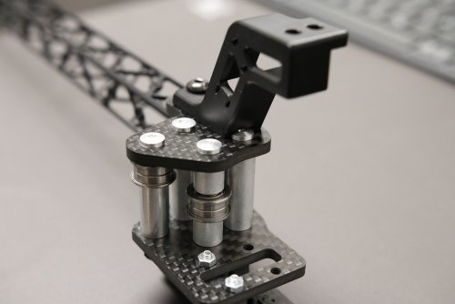
This Cable Bridge has been redesigned to fit a carbon or CNC aluminum XY joint where the screws are not flush with the top surface of the XY joint. This bridge also provides a little more distance from the cable chain. -
So I decided to self source Voron 2.4 R2 back in August I bought most of the parts so far I am going with 350x350x350 generic cable chains with SB and Rapido 2 HF with BTT Octopus and raspbery Pi 4 Extrusions from Aliexpress Motion kit from Aliexpress Pi 4 B2 2GB from Pi Hut BTT LDO motor kit from Aliexpress
-
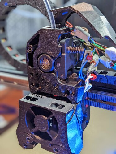
My Voron 2.4 running Klipper had been running great for a while but the afterburner assembly was starting to show weakness. I thought it was a good time for an upgrade so I installed a new Orbiter 2.0 with filament detector on my Voron 2.4 and the problems began...... witht he Orbiter 2.0 installed i have not been able to get my rotation distance anything like close to accurate. last print had massive over extrusion with lots of noise from the extruder. To statrt isolating the problem /as an experiment I ran 50mm (requested) filament through the extruder body only (no lower nozzle assempbly) and got about 250mm of filament instead. Fortunately the awful noise stopped. Ergo i think my initial problem is that the over extrusion i jsut discovered was overwhelming the nozzle and jamming. easy so far. On to the print config..... And incredible frustration as any and all changes to the print config file make no measurable difference in the amount of over feed. here is the code after a lot of trial and error and no change (i suspect there are a number of settings that i have turned off or on to see what if anything would happen- no change.). here is the code- ##################################################################### # Extruder ##################################################################### ## Connected to MOTOR_6 ## Heater - HE0 ## Thermistor - T0 [extruder] step_pin: PE2 dir_pin: PE3 enable_pin: !PD4 ## Update value below when you perform extruder calibration ## If you ask for 100mm of filament, but in reality it is 98mm: ## rotation_distance = <previous_rotation_distance> * <actual_extrude_distance> / 100 ## 22.6789511 is a good starting point #Bondtech 5mm Drive Gears AfterBurner ## 34.37086 for Bondtech 8mm gears (Galileo ## rotation_distance: 4.637 for Orbiter 2.0 rotation_distance: 4.637 ## Update Gear Ratio depending on your Extruder Type ## Use 50:17 for Afterburner/Clockwork (BMG Gear Ratio) ## Use 80:20 for M4, M3.1 # orbiter motor LDO-36STH20-1004AHG(XH) # gear_ratio: 7:1 microsteps: 16 full_steps_per_rotation: 200 #200 for 1.8 degree, 400 for 0.9 degree # max_extrude_only_distance: 500 # max_extrude_only_velocity: 120 # <- for orbiter motor LDO-36STH20-1004AHG(XH) # max_extrude_only_accel: 800 # <- for orbiter motor LDO-36STH20-1004AHG(XH) nozzle_diameter: 0.400 filament_diameter: 1.75 heater_pin: PA2 ## Validate the following thermistor type to make sure it is correct ## See https://www.klipper3d.org/Config_Reference.html#common-thermistors for additional options sensor_type: SliceEngineering 450 sensor_pin: PF4 min_temp: 10 max_temp: 270 max_power: 1.0 min_extrude_temp: 170 # control = pid # pid_kp = 26.213 # pid_ki = 1.304 # pid_kd = 131.721 ## Try to keep pressure_advance below 1.0 pressure_advance: 0.025 ## Default is 0.040, leave stock pressure_advance_smooth_time: 0.030 ## E0 on MOTOR6 ## Make sure to update below for your relevant driver (2208 or 2209) [tmc2209 extruder] uart_pin: PE1 interpolate: False run_current: 0.85 hold_current: 0.100 sense_resistor: 0.11 stealthchop_threshold: 0 # driver_TBL: 0 # driver_HEND: 6 # driver_HSTRT: 7 # driver_TOFF: 4 ###################################################################################################### ## I haven't made any changes above or below these lines so i the problem MAY be in here################################## ###################################################################################################### All of which leads me to my theory - incorrect wiring of the ldo-36st17-1004ahg to the tcm2209. Now i am very new to electronics and the instructions for wiring the Orbiter 2.0 to the V2.4 are yet to be found by me (if anybody has them, please share) so it would be an easy mistake. i feel like this is some sort of reversed polarity issue and leaves me with no idea where to begin with figuring this out. anybody got any ideas?
-
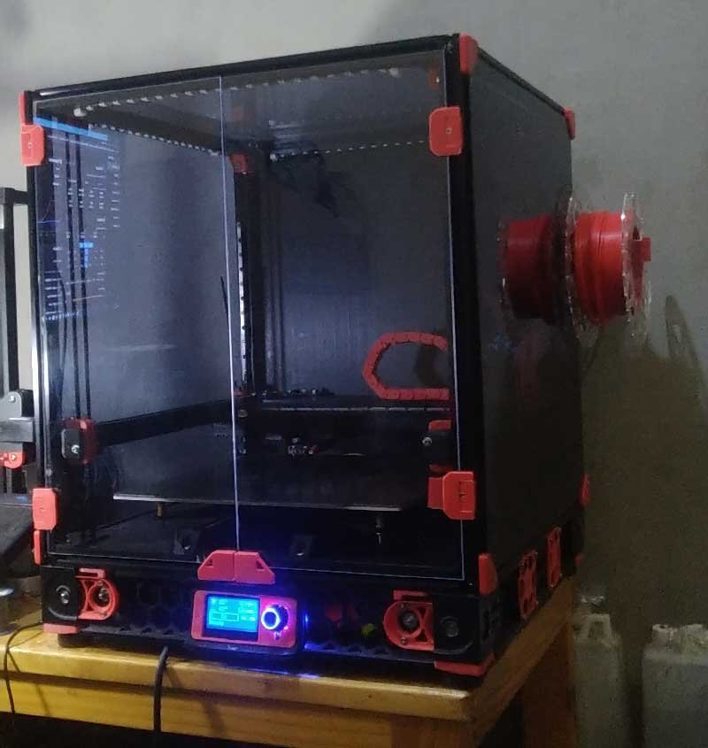
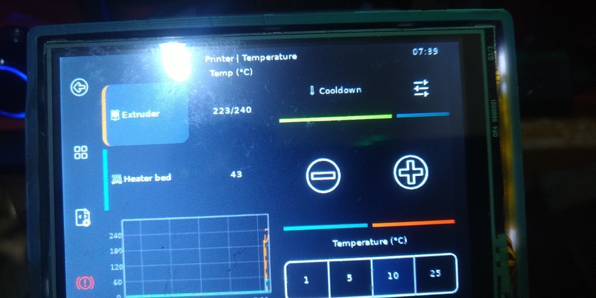
Hello, im new to 3dprinting, after i bought my first 3D printer then i saw Voron on youtube. took 3-4 months gathering the parts needed and finaly finish building Voron in december last year. and it was fun experience building it. here my build added Klipperscreen and now with stealthburner using LCD 3.5 inch touchscreen.. yep, it's small... and got best mod from here that i added to the build. thank you
-

orbiter Super Stealth Orbiter ( Orbiter 1.5 )
CityWrecker posted a file in Printable Voron User Mods
Version 3.1.3
574 downloads
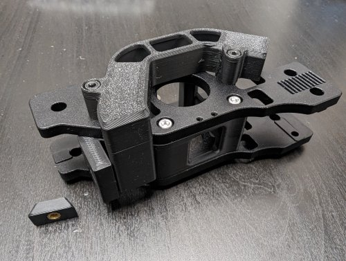
This is the Super Stealth Orbiter, a super low profile mount/housing for your Orbiter 1.5 with easy access for servicing the Orbiter without removing it from the printer/housing. After using 3dPmamsih 'Orbiter 1.5 for StealthBurner' for a few months I knew there were a few things I wanted to change. 1) To have an unbroken PTFE path from the exit of the orbiter directly down to the hot end. 3dPmamsih version had a break and required two pieces of PTFE with a bit of housing between. There were a few times my filament hung up in this section, so I wanted to remove it. 2) To break the full loop in front of the Orbiter that prevented the idler door from fully opening. This further prevented easy access to clean the gears and thus service or clean the extruder. 3) To have a proper Bowden tube coupler. 4) Various tweaks to the design to add additional reinforcement, rigidity, ease of assembly, and overall long term durability. 5) A sleek look that gives little to no indication of the extruder being used. This includes removing the thumb wheel from the idler tensioner and instead simply using an m3 bolt. In my case I find I can still tension to the desired amount with just my fingers and the bolt. I also don't tend to adjust this much once its set. PTFE path BOM: (Ill add this soon, but nothing special. If you have some m3 hardware and heat sets from your build you are probably good to go. Compatibility: Super Stealth Orbiter works with Orbiter 1.5 (I think that means the 1.0 should work too. Not sure.), the new MGN 12 based X-carriage (bolts go in from the front) and StealthBurner of course. Please do leave a comment and let me know how its working for you. If anyone wants to see a version for 2.0, send me one! Ill model it up and test it out. Don't need the motor, just extruder Finally, Ill try get a GitHub repo up for this as well. Thanks to 3dPmamsih. His design is the foundation for the Super Stealth Orbiter. I believe he adapted his design from Eytecz LGX lite mount, so big thanks to him too. (https://github.com/Eytecz/LGX_Lite_Stealthburner_CW2_style_mount/ ) "for his mount of lgx lite on SB to inspire me to complete this orbiter 1.5" .- 10 comments
-
- 8
-
-
-
- clockwork
- stealthburner
- (and 3 more)