Search the Community
Showing results for tags 'octopus'.
-
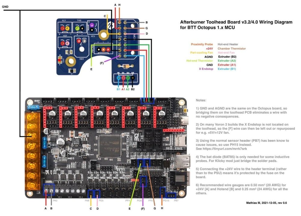
A wiring diagram for the Afterburner Toolhead breakout board connecting to and BTT (BigTreeTech) Octopus 1.x board. This is teh latest diagram after 4 different revisions with community involvement and support NOTES: GND and AGND are the same on the Octopus board, so bridging them on the toolhead PCB eliminates a wire with no negative consequences. On many Voron 2 builds the X endstop is not located on the toolhead, so the [F] wire can then be left out or repurposed for e.g. +5V/+12V fan. Using the normal sensor header (PB7) has been know to cause issues, so use PH15 instead. See Why isn't my probe working on the Octopus? The bat diode (BAT85) is only needed for some inductive probes. For Klicky mod just bridge the solder pads. Connecting the +24V wire to the heater terminal (rather than to the PSU) means it's protected by the fuse on the board. Recommended wire gauges are 0.50 mm2 (20 AWG) for +24V [A] and Hotend [B] and 0.25 mm2 (24 AWG) for all the others
-
So I decided to self source Voron 2.4 R2 back in August I bought most of the parts so far I am going with 350x350x350 generic cable chains with SB and Rapido 2 HF with BTT Octopus and raspbery Pi 4 Extrusions from Aliexpress Motion kit from Aliexpress Pi 4 B2 2GB from Pi Hut BTT LDO motor kit from Aliexpress
- 4 replies
-
- voron
- 3d printer
- (and 4 more)
-

Why isn't my probe working on the Octopus?
Demosth posted a question in Voron Electronics - Questions
I cannot get my Omron induction probe to work with the Octopus Board, what is wrong?


