

-
 8
8
-
 1
1
About This File
Maniac-Chamber-Lighting
This project uses 24V high efficiency white COB LED strip lighting to provide low glare interior lighting on a Voron 2.4 350/300/250.
One of the goals of this project is to simplify installation of lighting with snap in mounting brackets and pre-assembled wiring and junction boxes, and eliminate the use of screws. The commonly available adhesive backed 24V COB strips are cut to size and attached to each printed LEDBar. Length of strips will be a multiple of 50mm.
Aluminized Mylar tape attached to the LEDBar forms a corner reflector to improve light output. A combination of light baffles/diffusers on the side strips along with installation angle of the front and rear LEDBars prevents glare as the COB elements themselves are not directly visible when viewed from the front of the Voron. The lights are connected to a PWM MCU output that can be connected to a Klipper input button or Mainsail dimmer slider.
The LEDBars are designed to just fit along the top frame rails and include a 2mm JST connectors for easy installation and removal while servicing the printer. Printed brackets "permanently" snap into the 2020 and the LEDBars in tern snap into these brackets making for quick removal of the LEDBars as needed.
Printed zero clearance slot covers snap into the vertical 2020 extrusions and make for clean installation and wire management.
A printed TPU Z belt cover snaps into the 2020, making the wire run from the vertical 2020 section to the electronics bay non-exposed. A complete set of TPU parts to seal and support the base panel will be published later.
The design was prototyped on a Voron 350, but STL and STEP files are included for 300 and 250 printers. The LEDBars must be printed at a 45 degree angle to fit on the build plate. Double check that you can fit the LEDBar on your build plate before committing to the project and ordering parts. Set the infill angle to 0 degrees for the LEDBars.


BOM
| Qty | Item | Comment |
|---|---|---|
| 2m | 24V COB strip; 50mm segments; adhesive backed | https://www.amazon.com/gp/product/B0B9SFMZ1L |
| 1 roll | Aluminized Mylar Tape 1/2" (12.7mm) | https://www.amazon.com/gp/product/B07TYKFS8K |
| 10ft/3m | Red 26awg PTFE stranded wire | less than $0.15/foot ebay/Amazon/AliExpress |
| 10ft/3m | Black 26awg PTFE stranded wire | less than $0.15/foot ebay/Amazon/AliExpress |
| 4 | JST 2.0 4-Pin Male Connector plug with Wire + Female Connector plug(have not cable) | https://www.amazon.com/gp/product/B01DUC1S7S |
| 2 | gray 20 awg crimp terminals Ferrule Crimping Tool Kit, Preciva AWG23-7 with 1200PCS Wire Terminals Crimping Connectors Wire End Ferrules | https://www.amazon.com/gp/product/B073TZ5BBG |
| - | solder, rosin flux |
Printer Tuning
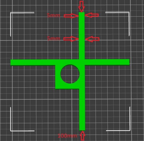
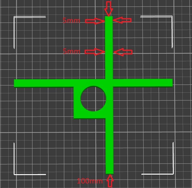
Print STL/Tools/Test.stl.
Measure the width of the 5mm arms at the two points indicated and verify they are within 0.05mm. Measure the length of the arms to be 100mm to be within 0.10mm. Check for no elephant foot. If everything looks good, print the STL/Common/LEDBar50.stl. Insert a Female JST plug and test fit the STL/Common/LEDRetainer.stl. Otherwise follow the tuning suggestions below
Test print width and length adjustment
The width of the 5mm section of the test print is primarily influenced by the slicer's filament extrusion multiplier. To dial it in, do two test prints with different extrusion multipliers and linearly interpolate between the two to determine the correct setting.
The 100mm length is primarily influenced by the filament shrinkage factor. Again, do two prints and linearly interpolate.
There is some interaction between the two settings so it may require some iteration.
Test print varying 5mm thickness
If the two 5mm width measurements differ, and assuming Pressure Advance is dialed in, chances are the difference is caused by temperature flow variation.
(Theory)- In the same way Pressure Advance has to build up pressure at the beginning of a new extrusion to control print width, there is a secondary factor that the extrusion pressure builds slightly on long high flow rate lines because the extrusion temperature of the melt decreases. At high flow rates, the filament has less time to reach full temperature compared to printing slowly. This effect is very pronounced with TPU but also observed with ABS. The net effect is over extrusion once the flow rate decreases as in the case of a 90 degree turn. Pressure advance does attempt to decrease pressure when decelerating but it does not take into account the pressure increase due the temperature drop and the increased flow as the temperature returns to a normal level with the flow decreases... bottom line don't use the 30-second Benchy settings - try decreasing the peak flow rate/print speed to minimize the effect.
Elephant Foot
After getting the flow rate dialed in, remove any remaining elephant foot by decreasing the flow rate of the first layer or re-adjust the z-offset to increase the first layer height.
Printed Parts
Print after calibration:
Common Printed Parts
[alt] CornerJunctionBox.stl        -left rear & right front
[x2]  CornerJunctionBoxMirror.stl  -left front & right rear recommended
[x4] CornerJunctionCapLarge.stl
[x4] CornerJunctionCapSmall.stl
[x3] LEDClip15.stl  -front
[x9] LEDClip45.stl  -side & rear
[x4] LEDRetainer.stl
[4x-ABS] Z Belt Cover Retainer.stl
*** Test print first TPU part and trial fit before printing others Shore 95 TPU ***
[x1-TPU] DeckCornerLeftFront.stl
[x1-TPU] DeckCornerLeftRear.stl
[x1-TPU] DeckCornerRightFront.stl
[x1-TPU] DeckCornerRightRear.stl
Voron 350
[x2] LEDBar350.stl        -set infill angle to 0 deg
[x2] LEDBar400.stl        -set infill angle to 0 deg
[x4] LEDdiffuser350.stl   -check for gaps in 1st layer; might need to reduce infill line width 140%=>120%
[x4] LEDdiffuser400.stl   -check for gaps in 1st layer; might need to reduce infill line width 140%=>120%
[x2] SlotCoverVert200.stl
[x2] SlotCoverVert287.stl
Voron 300
[x2] LEDBar300.stl        -set infill angle to 0 deg
[x2] LEDBar350.stl        -set infill angle to 0 deg
[x4] LEDdiffuser300.stl   -check for gaps in 1st layer; might need to reduce infill line width 140%=>120%
[x4] LEDdiffuser350.stl   -check for gaps in 1st layer; might need to reduce infill line width 140%=>120%
[x2] SlotCoverVert200.stl
[x2] SlotCoverVert237.stl
Voron 250
[x2] LEDBar250.stl        -set infill angle to 0 deg
[x2] LEDBar300.stl        -set infill angle to 0 deg
[x4] LEDdiffuser250.stl   -check for gaps in 1st layer; might need to reduce infill line width 140%=>120%
[x4] LEDdiffuser300.stl   -check for gaps in 1st layer; might need to reduce infill line width 140%=>120%
[x2] SlotCoverVert200.stl
[x2] SlotCoverVert187.stl
Assembly
LED Bar
-
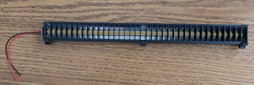
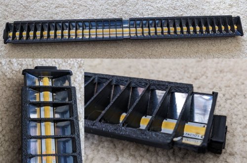
Precisely cut a section of the COB strip to match the length of the LEDBar using a sharp razor. The LEDBar400 uses a strip with 8 50mm sections.
-
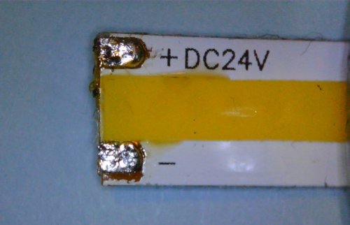
Identify the end of the strip with the correct +/- orientation and scrape/abraid any oxide or coatings from the contacts using fine sand paper or razor until clean copper is exposed.
-
Tin the contacts and wipe away any excess solder with a paper towel or solder wick. https://github.com/VoronManiac/Maniac-Chamber-Lighting/raw/main/Image/TinnedCOB.jpg?raw=true
-
Remove the center two pins of the female JST connector. They'll slip out of the PCB side of the connector with enough force. Tin the remaining two pins.
-
Place the LEDBar into a small tool vise if available to help hold things in place. This helps immensely.
-
Test fit the JST connector into the LEDBar. Test fit the LEDRetainer by placing it over the connector and pressing it into place (it will need to be removed so don't force it). Dry fit the COB strip under the connector and note the alignment of the tinned pads and the connector pins. Check that that there is enough room for the un-tinned end of the COB strip to lay flat.
-
Remove the middle wires on the male JST connector using an Exacto to pry up the retaining tabs on the JST plastic housing. Swap wires as needed to have Red on the "+" pin and Black on the "-" pin
- Remove the LEDRetainer, and male & female connectors.
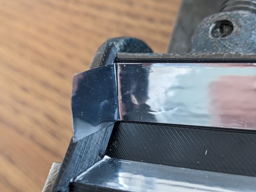
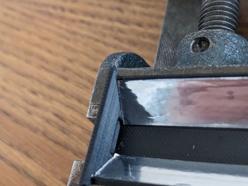
- Apply Aluminized Mylar tape strips. Position the tape at the edge of the LEDBar. Starting a few inches in, begin pressing the tape in place, working to the end of the LEDBar. Crease the tape into the corner with a toothpick and trip off the excess.
https://github.com/VoronManiac/Maniac-Chamber-Lighting/raw/main/Image/PXL_20230326_192127167.jpg?raw=true https://github.com/VoronManiac/Maniac-Chamber-Lighting/raw/main/Image/PXL_20230326_192234882.jpg?raw=true
- Peel back sections of the protective COB strip backing and incrementally attach the COB strip, centering it between the Mylar strips. The COB strip should be positioned so it starts exactly next to the raised bar on the print. The LEDBar is ~2mm longer than the strip, so when the COB is installed, the un-tinned end of the COB strip should not hit the far end of the LEDBar. Once attached, run a blunt soft object like a popsicle stick or round edge of a credit card along the white COB strip edges to firmly seat it.
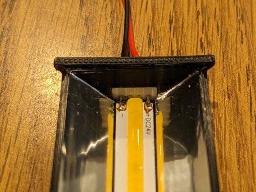
- Re-install the female JST connector and LEDRetainer. Solder the JST connector to the COB strip. Connect to 24V supply and test COB.
Junction Boxes
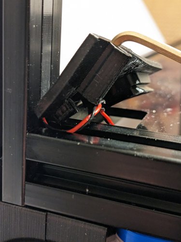
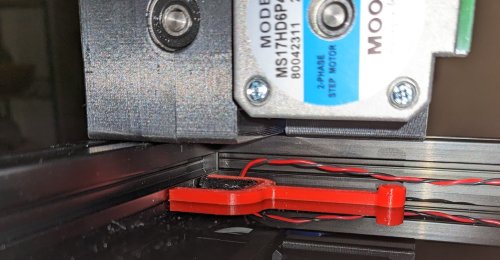
The junction boxes snap into the upper rails at opposite corners of the printer. Each junction box services two LEDBar's and feeds wires down the 2020 vertical rail. The junction boxes can be removed by gently prying them from the frame until each end of the box pops out of the 2020. With a little care, breaking the snap tabs is not an issue.
-
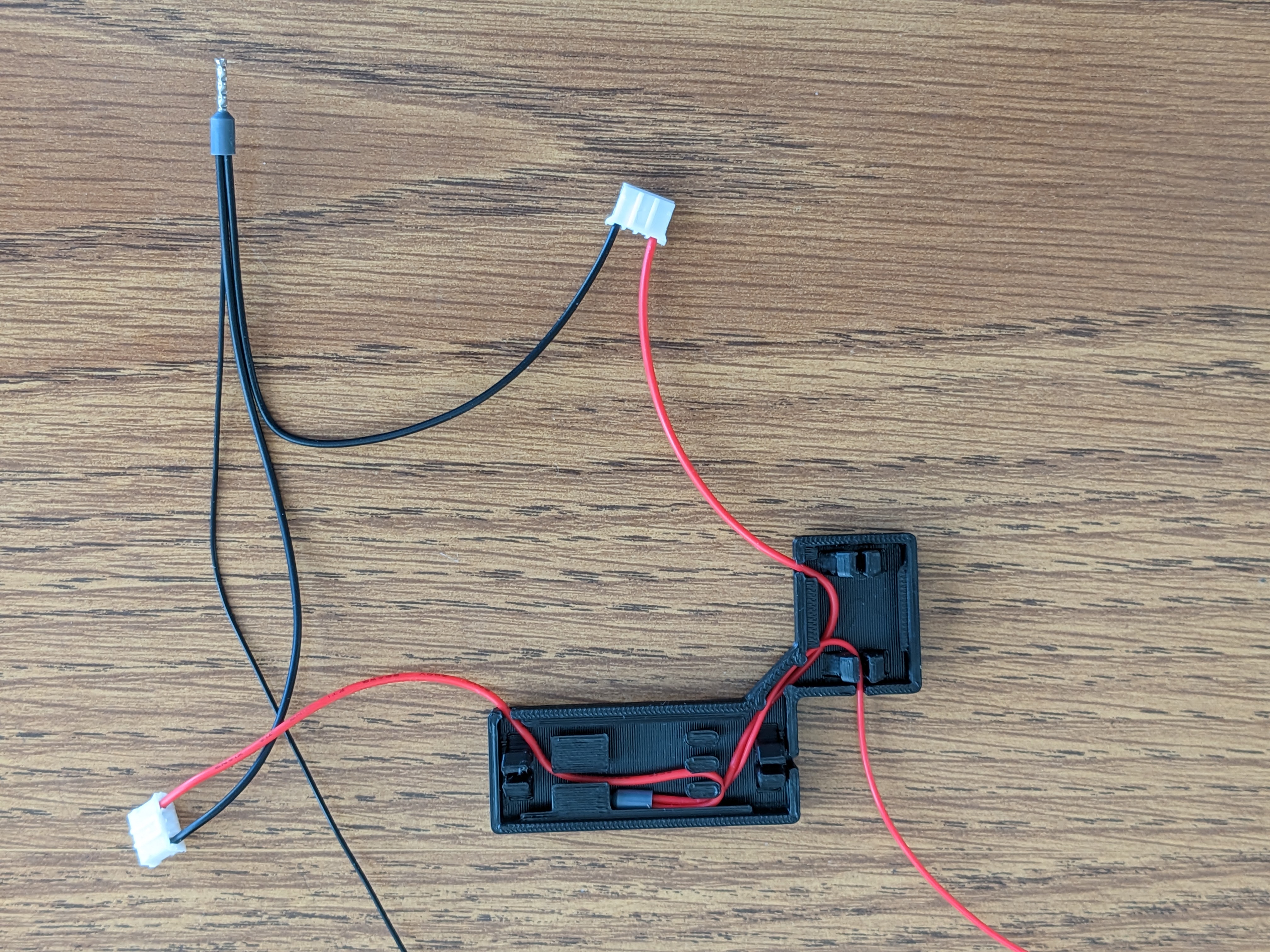
A pair of red/black wires runs from each junction box into the MCU board in electronics bay. A "Y" splitter joins the front and back LED feeds for final connection to the MCU. The required length of the wires will be dependent on the machine size, electronics bay wire routing path and location of the MCU. For a typical Voron 350, 1.7m and 1.1m wire lengths seem to work. When figuring the required length, add in and extra 10% that will be taken up when the wires are twisted together.
-
Be sure the two center terminals and wires from each connector have been removed by prying up the retaining tabs on the connector with an Exacto to free the wires. Re-insert wires as desired to have the Red wire match up with the "+24VDC" pin on the LEDBar and a Black lead match up with the "-".
-
Cut the wires of two male JST connectors to 112mm and strip 8mm of insulation off each end.
-
Remove 8mm of insulation from the ends of the PTFE wires.
-
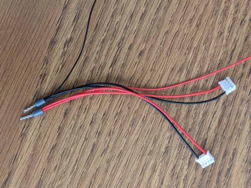
Twist the bare red wires from the two connectors and PTFE wire together and insert into a gray 20 awg crip terminal and crimp. Twist and crimp the black wires in a second crimp connector. https://github.com/VoronManiac/Maniac-Chamber-Lighting/raw/main/Image/PXL_20230324_170353732.jpg?raw=true
-
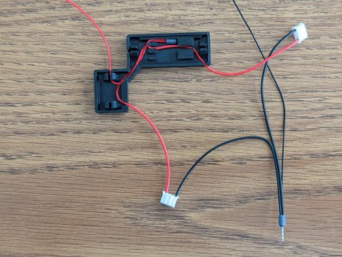
Insert crimp into junction box and route red wires as shown below https://github.com/VoronManiac/Maniac-Chamber-Lighting/raw/main/Image/PXL_20230324_173040693.jpg?raw=true
-
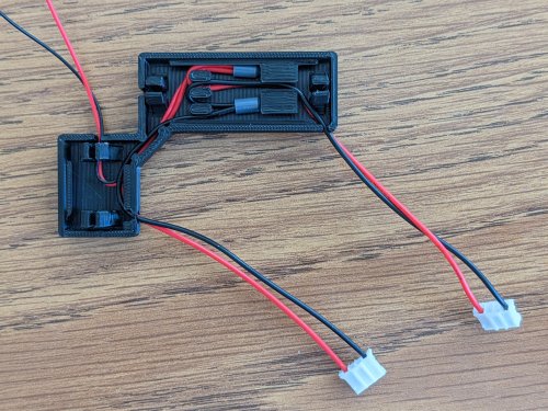
Insert crimp into junction box and route black wires as shown below https://github.com/VoronManiac/Maniac-Chamber-Lighting/raw/main/Image/PXL_20230324_173913668a.jpg?raw=true
-
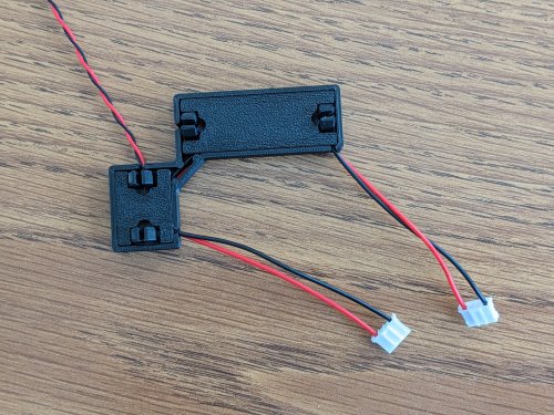
Install large and small snap in covers. With junction box is a vise, place a piece of tape on the far end of the red/black wires and insert into drill and create a twisted pair. To help keep wires from untwisting, pass the twisted pair around a round object like a pencil along the length of the wires. This helps wires take a new set.
Installation
-
Snap a junction box into the top frame.
-
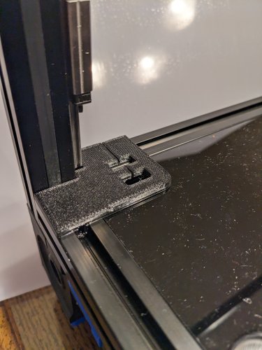
The slot covers are split into two sections to ease installation. Lower the Gantry and install the top slot cover.
-
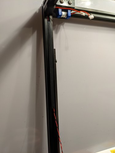
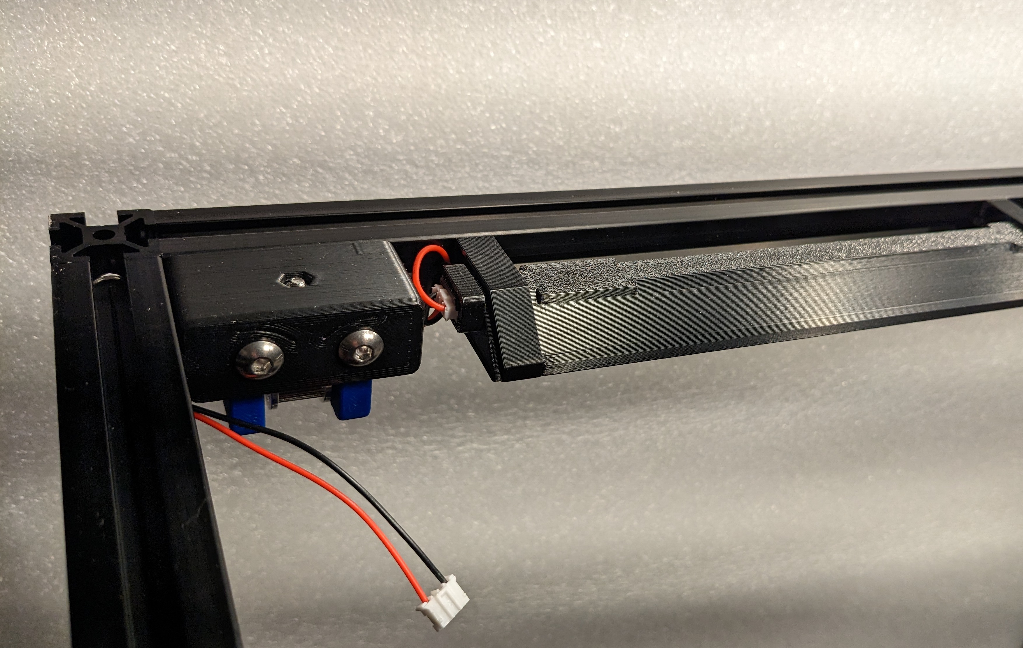
Starting at one end, gently push the slot cover into place being careful not to pinch the wires. Applying a slight tension to the wires keeps them inside the slot cover. Once the slot cover is fully pressed into place, the slot cover will side in the 2020 channel with minimimal effort. The wires should free loose when jiggled. https://github.com/VoronManiac/Maniac-Chamber-Lighting/raw/main/Image/PXL_20230327_053830500.jpg?raw=true
-
Raise the gantry. Slide the top slot cover upwards as needed and install the lower slot cover. https://github.com/VoronManiac/Maniac-Chamber-Lighting/raw/main/Image/PXL_20230327_055426979.jpg?raw=true
-
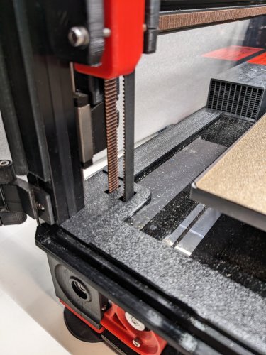
Bend TPU Z cover open and slide Z belts into slots. Press far side into 2020 channel.
Some of the pictures below were taken on a new Voron that did not have the Z belts installed yet. For an existing machine there is no need to remove the Zbelts to install the Z belt Covers
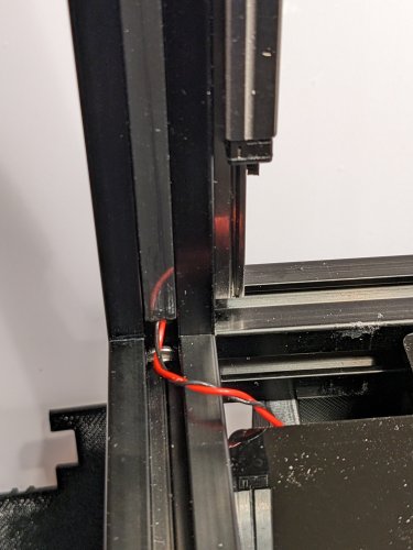
- Position the twisted pair so it is clear of the remaining TPU tab and gently press the it into the 2020. Use a small screw driver to to guide the wires and keep them from pinching. between the tab and the 2020.
- An allen wrench provides a convenient lever for removing the TPU tabs from the 2020. The TPU can also be removed by wedging a small screw driver between the 2020 and the TPU. https://github.com/VoronManiac/Maniac-Chamber-Lighting/raw/main/Image/PXL_20230327_055824980.jpg?raw=true https://github.com/VoronManiac/Maniac-Chamber-Lighting/raw/main/Image/PXL_20230327_060104321.jpg?raw=true
-
Snap the Z Belt Cover Retainer(s) in place to hold the Acrylic deck panel against each Z belt cover. https://github.com/VoronManiac/Maniac-Chamber-Lighting/raw/main/Image/PXL_20230328_041948365.jpg?raw=true
-
Snap diffusers and 45 degree mounting clips on the side LEDBar's to test fit. The mounting clip ends easily unsnap by pressing them over the lip of the LEDBar.
-
Plug the JST connector into the LEDBar. For initial installation of the LEDClip15, they can be inserted into the 2020 one by one and slid into position, or the entire LEDBar can be snapped in as a unit. Not necessary, but the diffusers can be locked into place so it doesn't slide with a drop of CA.
-
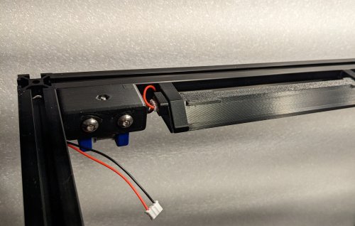
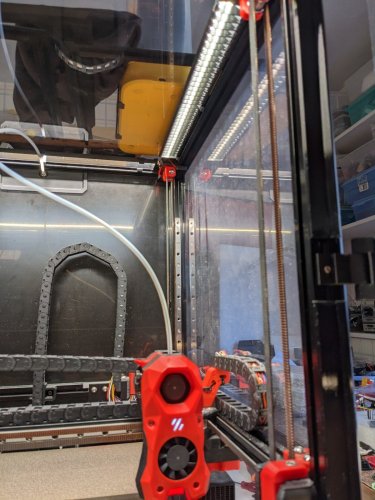
Installed LEDBar https://github.com/VoronManiac/Maniac-Chamber-Lighting/raw/main/Image/PXL_20230328_043655822.jpg?raw=true
TO DO
- update pics
- add on/off/dim switch & macros
- publish Lower Panel Deck TPU seals & retainers
- publish TPU Side/Top/Rear Panel & Front door seals, Retainers & hinges
- publish Maniac-Aire HEPA/Charcoal filters
- publish Maniac-Drybox

