Leaderboard


Popular Content
Showing content with the highest reputation since 08/27/2021 in Tutorials
-
So... just an small introduction. I´ll skip the phisics and the electronics of it as I´m not a reliable source and will hit the practical bit. This post will be of use if you want to check the actual reading of your thermistors (fairly irrelevant) or if you want to reliably swap printers with the same material profile(for us geeks with 3 or 4 printers, much more relevant). To do that, you´ll need an external thermocouple reader and two thermocouples. I´ll show you what I use, and I'll also show you what to use to get the same results on the budget side. 1st you need two K-type thermocouples. First a 1.5mm probe with about 20cm of lenhgt, and second a "pinpoint" style probe. Quality and precision are not a thing. You don´t need it. Don´t go to RS instruments to buy the most expensive probe you find (somewhere around 100quid) a 5 euros amazon special will do. Why? because you don´t ultimately care about the actual temperatures, but what you need is a constant and repetitive source. In this picture you can see the probe(green lead), the thermocouple reader and the pinpoint thermocouples(blue leads with a dotty end). You will use the probe for the hot end, and the pinpoints with aluminium/foil tape for the Bed. Start with your known and reliable printer (or the one that has the profile that works) and find the way to wire it like this: For the hot end, you may want to pre-heat it as you will have to push the last bit of filament down with the probe till the probe is stuck at the tip of the nozzle. In some hot ends is easier to drop the heatbreak and do the temperature checks OFF the hot end... (in my biqus for example) In some Voron Hot ends that may be an absolute pain and maybe would be a good idea for you to do so before you close your hot end during the build. Now the results: Channel 1, Bed. Target 80 reading 69.3 Channel 2, hot end. Target 250. Reading 239. The reading in the hot end, is for example the same I was expecting, In all of my printers (but in the one running duet) I have a 10 degrees drop above 200 degrees at the hot en as I use the same chinese shit thermistors with SKR boards. However the one running a duet board reads SPOT ON, so that printer has all her profiles dropped by 10 degrees. In the bed, honestly I would expect to see a perfect reading, and on the PEI sheet I do after some soaking(+/- 2 or 3 degrees max), but on the glass bed, with the magnetic layer in the middle, I lose about 10 degrees for each 70... so, when I´m at 110 degrees, my actual reading is like 95. So all my profiles for glass printing have been bumped accordingly. Is a good practice to check if your error is linear or constant. In the case of my hot ends the error is constant and is due the poor calibration (and the wrong use) of 100K thermistors. Ideally they should not be use outside of its operational range of precision (somewhere between zero and 80 degrees), but they are cheap and considered to be "sufficient" for the application. In the case of my bed, the drop is linear rather than constant. Is a function of some thermal equation that "X" amount of heat is lost between the plate and the glass. The most heat you apply the greater will be the loss. So you will have to manually bump the bed to different temperatures, let it stabilise and check what is the actual value. Once you get 3 or 4 points, you can pretty much guesstimate the error at any temperature plotting it in excel. Now, go to your other printer, repeat and compare results. Finally adjust your profile for the target printer with the bumps or drops on temperature you´ve observed. There is a way to "manually" tweak the thermistors for them to read what you want. IE, if a printer is WAY off (30 or 40 degrees) you can change the beta tables and with a bit of trial error you´ll get there(in rrf at least, not sure in klipper). However, is normally easier to just scrap that thermistor and get another one that reads closer to the truth. Oh. The budget option. Yeah, instead of buying the all professional multi reader for K thermocouples (not that expensive... south of 40 quid IIRC), you can buy actual K thermocouple thermometers for 5 quid in ebay/amazon/alichinese https://www.aliexpress.com/item/32816531406.html?pdp_npi=2%40dis!GBP!£3.17!£3.17!!!!!%40211b4cff16788334610715611e535f!64728868128!btf&_t=pvid:16a01e1f-9799-46ad-b102-db102b175498&afTraceInfo=32816531406__pc__pcBridgePPC__xxxxxx__1678833461&spm=a2g0o.ppclist.product.mainProduct Even will come with the actual Dotted thermocouple so you´ll only have to buy the probe.7 points
-
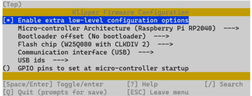
Initial setup of UART Jumpers on the ERCF Fly Board v1.1 Make sure that you install the jumpers as shown below or you will run into issues further down the line. Flashing klipper to the Mellow ERCF Fly Board v1.1 to use a USB connection. SSH into the Raspberry Pi On the Flyboard hold down the SW1 button and attach USB cable to Raspberry Pi (or other micro board) then let go of reset button. Type lsusb Look for ‘ID 2e8a:0003 Raspberry Pi RP2 Boot’ in the list of devices. If it is not present repeat the process. When you have confirmed that ‘ID 2e8a:0003 Raspberry Pi RP2 Boot’ do the following: cd ~/klipper make menuconfig Select the following options for a ‘USB’ (not CAN) connection to your printer. Make sure enable extra low-level options is selected. Exit & save make -j4 #This will compile the firmware for the ERCF Fly Board v1.1 make flash FLASH_DEVICE=2e8a:0003 #This will flash Klipper to the ERCF Fly Board v1.1 If successful it should look like the image below: Disconnect and reconnect the ERCF Fly Board v1.1 USB connection from your Raspberry Pi and reboot your Printers Host You can then move onto installing ERCF-Software-V3 "Happy Hare" by moggieuk Instructions here: moggieuk/ERCF-Software-V3: New software driver for ERCF control under Klipper (github.com) If your flashing was successful, you will be able to use the ‘Fystec ERB Burrows Board’ option throughout the install as it will detect the ‘Raspberry RP2040’ mcu. Use gpio(then the corresponding pin number) in your ercfhardware.cfg e.g. gpio20 for the endstop (P20) & gpio7 for the STEP pin on gear stepper (GPIO7) Note: adding a ‘!’ before gpio will change the movement direction. Hopefully that will help someone!6 points
-
Disclaimer. There are limits to what you can convert. Complex models with lots of fillets and chamfers are very difficult if not impossible to convert. This tutorial is will allow you to convert most simple parts so that they can be readily modified to suit your needs. OK, with that out of the way, let's get started. 1. Launch Fusion 360. Fusion will automatically open a "New Design" and that is where we'll start. 2. Navigate to the mesh environment buy clicking "MESH" on the top portion of the Fusion window. The menu along the top will change and the icons will look like the ones in the picture below. 3. Fusion employs a workflow that that moves from left to right along the top of the screen. What I mean by this is that the first icon you click will be the furthest to the left and your next step will be one of the icons to the right of the first one and so on. The icons are also grouped to follow the workflow as well. Our workflow is Create -> Prepare -> Modify and it's labeled under the icons.. So let's click the "Insert Mesh" icon in the "Create" section, it's the 1st one on the left (Yellow Hexagon with blue arrow). When you do, a window will appear where you can navigate and select your mesh object (STL). Click the object, click "Open" and your mesh object will appear inside of Fusion. Fusion gives you the chance to orient, move, scale the object before you commit but, most of the time you just need to accept the default by clicking OK. 4. Next we'll create "Face Groups". Click the "Generate Face Groups" icon (above PREPARE). Select the mesh you just imported and click the "Preview" checkbox to view the mesh groups. As you can see Fusion has grouped the faces based on an angle threshold. Most of the time the default value will get you where you need to be. Of course you can modify the angle value and experiment if you don't get desired results. Basically you want discreet groups as is shown below. Where you run into trouble is when there are a lot of radii on the part and the groups start to run into each other. I'll do another tutorial on reverse engineering a part for the parts that you can't convert in the near future. So, Now that I'm satisfied with my mesh groups... Click OK to accept. 5. Next we'll convert the mesh to an editable solid. Click the "Convert Mesh" icon. It's the far right icon in the "Modify" section of the top menu. Select the mesh body. Make sure the Operation is set to Parametric and the Method is set to Prismatic. Click OK to accept and that's it! All done, easy peasy. The part will turn grey indicating that it's now an editable solid. 6. Now that we have an editable solid we leave the "MESH" environment and switch to the "SOLID" environment so that we can modify the part. Good luck and happy creating!6 points
-
So: in my past tutorial I've explained you how to measure the actual values of your hot end and bed to reliably transfer material profiles across your printers modifying them accordingly... What if bring you a way to harmonise your profile across your printers? I know there is people here that sticks to a single combo board/extruder/thermistor... therefore the error between printers will be minimal. However for the rest of mere mortals that use whatever hotend was available, and batches of thermistors sold by weight from the finest china, the errors btween printers can be over 25 degrees. For example while doing the previous tutorial i found out that moving the duet board from RRF to klipper was under reading by 15 degrees... And the fysect board in my zero was over reading by 9... that basically means that any material that i tune in the zero, if try to print it with the same settings in the duet machine, it will definitely be over melted. here I present you the pull_up resistor value in klipper (by default 4700ohms). What is a pullup resistor you will ask? Is basically a resistor included as a reference in a circuit where the resistance value of the sensor can't be measured so this passive resistor in the circuit, works as refference. If you modify the value of this resistor in klipper, it will alter the reading on the thermistor allowing you to tune your readings and leaving them spot on no matter the brand of your board or how chinese is your thermistor. Start as before. Go to your preferred printer and preheat the hot end to your desired temperature. Stick the probe inside, and check the reading onto the nozzle. It will likely be off. If it is reading over, you will need to decrease your pull_up resistor value (remember the starting point is 4700) If is reading under, you will need to increase said value. By how much i hear you ask... well... is a bit of an art, but I warrant you that you'll match it close enough at the 3rd iteration. I've found that modifying the resistor value by twice the percentage error, is a decent approach. Example: Target reading: 250. actual reading: 235 Pull_up value 4700 250-235=15 If 250 is 100% then 15 is 6% 6%x2= 12% New resistor value= 4700+(4700x12/100)=5226. Save config and reboot. Repeat operation. Till the measurement in your thermocouple reader is within 2 degrees of your reading. Go across your printers and do the same. Now you will have the exact same reading across all your printers. Example of my duet cartesian vs my micron, and the resulting values. Now. Note that you will only be able to tune spot on a limited range of temperatures, and if you try to heat at 300 sfter tunning at 250 you will likely be off by 6/8 degrees. However, and I have prooven this with 5 different setups, they all will be off by the same ammount or very similar. In my case I have checked the readings from 200 to 330 and tuning it at 250. All the printers individualy have had an error of no more than 8 degrees but more importantly the error across all of them was under 2 degrees, that makes the profile perfectly transferable. Notes: *to be repeated if you change thermistors or thermistors wiring.... ie adding a connector *let stabilise the temperature for at least 2 minutes in each reading point.6 points
-
Hi All, What is Fusion 360? Fusion 360, as the name implies, it's a collection (or Fusion) of mechanical and electrical design, drafting, rendering, analysis, assembly and manufacturing software tools that together create a fully featured Computer Aided Design package that can be used to design pretty much anything you can think of. For this and subsequent tutorials we'll focus primarily on the creation and modification of 3D models that can later be printed using a 3D printer. If you don't have Fusion 360, you can download it here. First a little background about 3D CAD modeling software. The majority of CAD modellers currently available are considered feature based solid modellers. These modellers (Fusion is one of them) allow for the creation of 3D models by adhering to the following methodology... Create a 2 dimensional reference sketch or drawing onto a planar surface, then apply a command to create a 3D feature. The basic feature types are, Extrude (in a given direction), Revolve (about some centerline), Sweep (along a path) and Loft (blend from one shape to another shape). These features can both create positive 3D objects or negative 3D objects that cut or remove geometry from existing 3D geometry. In addition to sketch driven features there are also features that can modify existing geometry such as round or bevel external edges or internal corners, etc. Feature based solid modellers let the user parametrically drive and modify the dimensions in the model creating a very powerful and flexible design tool. CAD designers generally employ one of two methods to create or design components in the context of an assembly. The first and most basic is called "bottom up design". This is where the designer creates individual parts or components and then assembles them together in an assembly. The second is "top down design". We're going to focus exclusively on Top Down Design because top down lets us model all of our components in an assembly context and lets us reference the location and edges, radii, etc. of other components so that when we make a change to the assembly... the change parametrically cascades and updates all of the parts affected by the change. With the old bottom up way, you have to hunt around and change each part and it's easy to miss something. While my tutorial will get you started... it is by no means a full on lesson going over every aspect of Fusion 360. There are tons of YouTube video tutorials by many outstanding content creators and I encourage everyone to supplement this and future tutorials with some of those videos which do a much deeper dive into Fusion 360. OK, let's go! In this tutorial we'll make an impossible dovetail cube. 1. Launch Fusion 360. It will automatically place you into the "Design" workspace. Across the top are commands to create and modify features along with tools to navigate around the workspace. On the left side is the "Browser" it lets you control and activate components, joints and other aspects of the assembly and lastly on the bottom of the screen is the Timeline where you can access and rearrange features. I recommend using the following as a reference Tour the Interface as it's easy to get lost in the menus. 2. Set units to millimeters by expanding Document Settings and clicking Units. Select Millimeters and accept by clicking OK. If you think you're going to use millimeters most of the time then it's a good idea to set it as default or maybe you already chose it when you setup Fusion. 3. Next we'll create a sketch on a plane. The sketch icon is the first icon in the upper left corner. Pro Tip: You can hover over an icon to see what it does before clicking on it. When you click on it... 3 planes and axes will appear in the center of the work area. Select the middle one (blue). 4. You'll notice that once you click on a plane the menu switches to sketch mode and the 2D sketch tools appear on the menu bar across the top. Select Create, Rectangle, Center Rectangle. 5. Click the little origin icon in the center of the workspace and drag to create a square. Just eyeball it for now. Don't worry about the size. 6. Next we'll add some dimensions. Before we do however, understand that while it's not required it is good practice to fully constrain your sketch geometry. When constraining geometry we must define the size and the location and/or orientation of the geometry in the sketch. When we clicked on the origin point to place the rectangle, we automatically locked or constrained the center of the rectangle to the origin of the sketch. We can see that it's constrained because the center dot is black. Light blue objects are unconstrained, black objects are constrained. When all the geometry is fully constrained, everything will be black. In addition, you can see the physical constraint symbols placed on or near the geometry. We can add or delete as many physical or dimensional constraints as needed to fully constrain the sketch. OK, enough talk, click the dimension icon (or hit the "D" key on your keyboard) in the tool bar across the top of the screen. Next click either the top or bottom horizontal line and then click to place the dimension. Once the dimension is placed hit the enter key. It should look like I have it below. Also don't worry about the dimension value at this point, we will dial that in later. 7. Next we'll add an = (equal) constraint to one of the vertical lines. We want this to be a square so all sides need to be equal and we achieve that be creating an equal constraint between one of the horizontal and vertical lines that make up the square. Click the red/black equal constraint icon near the middle of the top tool bar. Click on a horizontal line, then on a vertical line. Press escape to exit the equal constraint command. You'll notice that all of the geometry turns black and you'll also see the addition of two equal constraint symbols. While we're at it let's change the size of our 2D cube to 30mm. Double click on the dimension, change the value to 30 and hit enter to accept. 8. Exit the sketch by clicking Finish Sketch in the Sketch Palette dialog box. 9. Activate the default 3D view by clicking home icon that appears when you move your mouse near the ViewCube in the upper right corner. You can click on any of the faces or corners of the ViewCube to change your view orientation. To zoom in or out use the scroll wheel on your mouse, click and hold down the scroll wheel while moving the mouse to spin the model. Once we have some actual 3D geometry on the screen you can try zooming and spinning the model around and you can always get back to the home 3D view by clicking the home icon. 10. Next well extrude the square to create a 3D cube. Click on the extrude icon (top tool bar). When you do you'll be asked to select a profile. Profiles are enclosed regions that solid features can be created from. For this tutorial we're only creating one feature (shape) from a single profile but... you can create multiple features (shapes) from the same sketch if you want. in addition, there are a multitude of options when creating extruded features and the extrude command can either create, cut or join other features but... For now we're keeping it simple. Select the 30mm square profile and enter 30 for the distance. Once you have accept by clicking OK. Congrats! You have just modelled a 30mm cube. 11. Now is a good time to save your work. Click on the save icon, give it a name and click OK. 12. Next we're going to create another sketch but this time it will be on the face of an object. Select Sketch and click on the left side face of the cube. 13. You should now be looking at the flat face of the cube that you selected, if not click "Look At" in the Sketch Palette. Select Line from the sketch menu on top and connect one end of the line to the middle bottom of the square and the middle of the top. You will notice that the line wants to snap to the middle, edges and corners of the existing geometry of the cube. This is exactly what we want the line to do because this line will end up being our vertical centerline thru the middle of one side of the cube. I'll be highlighting areas of interest as we go along. 14. Next we'll draw 3 connected lines horizontally across the middle of the cube. I've numbered the 3 line segments, the center one is highlighted in blue. Ensure that the lines go from the mid point (triangle symbol) on one side to the mid point of the other side. I know this sounds weird but it will make sense in the next step. 15. Now we'll make the 3 lines equal by selecting the equal icon from the constraints menu at the top and clicking the left line and the middle line. Next click the right line and the middle line. Now all 3 lines are equal to one another. 16. Next we'll convert the sketch lines in construction lines. Construction lines are reference lines that are ignored when making features. Select all of the vertical and horizontal sketch lines and then click the construction icon in the Sketch Palette. 17. Now sketch two lines as shown. Just eyeball the location for now. 18. Now we're going to create a midpoint constraint between the midpoint of the angled line and the left endpoint of the middle horizontal construction line. Select the Midpoint constraint from the constraints menu at the top of the screen. Click near the midpoint of the angled line and then the left endpoint of the middle construction line endpoint. Once you do you'll see the triangular midpoint symbol. 19. Next we'll mirror the two lines over to the right using the vertical construction line as our mirror line. Select mirror from the top menu. Select the horizontal and angle lines as your objects to be mirrored and then select the vertical construction line as your mirror line. Click OK to accept. 20. Create a line between the two angled lines as shown. Next select the dimension command and create two dimensions. One vertical dimension and one angular, click the horizontal line and angled line to create the angular dimension. Modify the dimensions to 5mm for the vertical and 60 degrees for the angular. As you can see, we only need two dimensions to constrain and control this sketch because the mirror command automatically creates symmetric constraints between the right and left sides. In addition, the 3 equal construction lines maintain equal proportions of the dovetail. We could delete the center equal constraint and add a horizontal dimension in it's place to make it variable. Click Finish Sketch. 21. Now we'll create a construction plane. Click the home button by the viewcube. Now select the "Plane through two edges" command and click the two vertical edges of the cube. If your screen looks like mine click OK 22. Next we'll create another sketch on the plane that we just created. Click the sketch icon and then click on the plane we just created. Make sure your in a 3D view when you do this to help illustrate what we trying to achieve. The impossible dovetail works because we've rotated the cutting plane 45 degrees. You'll see... We'll now use the project command to project the lines from the previous sketch onto this sketch. Select the project command from the create menu at the top of just hit the letter "p" on the keyboard. Select the lines highlighted blue and click OK to accept. 23. Next well turn the vertical projected line into a center line. Select the vertical line and then select centerline on the Sketch Palette. 24. OK, Now let's mirror the projected lines on the left, over to the right. This should be a walk in the park. Just like we did before. Select the mirror icon, then select the projected lines on the left and since we converted the vertical line into a centerline... Fusion automatically selected it for us. Select OK to accept. We can now exit the sketch. 25. OK we're finally at the home stretch. Let's do a little housekeeping first though. Expand "Sketches" in the browser on the upper left. Then click the eye symbol next to sketch2. Clicking the eye is like a light switch. It doesn't delete or disable the sketch, it just toggles it's visibility, the same is true for any item in the browser you can show or hide objects any time. Now your cube should look like mine. 26. Let's get to cuttin'!!! Select the extrude command from the top menu to bring up the extrude dialog box. At the top of the box select the Thin Feature icon and select the lines from our last sketch. In the extrude dialog make sure the "Direction " is set to symmetric, "Distance" is 30mm, "Wall Thickness" is .2mm and Wall Location" is set to center. Click OK to accept. 27. Congratulations! We now have two solid bodies that we can 3D print. 28. Before I go... Let me show you how to save the bodies as STL files for printing and a couple other tips. Remember, you can hide/show object by clicking on the eye icon in the browser. You can also rename the bodies by clicking twice. Right clicking on one of the bodies brings up a menu. Select "Save as Mesh" to open a dialog where you can configure and save one or both bodies as an STL or 3MF file. Lastly... Every dimension can be changed by right clicking the feature icons on the timeline at the bottom. If, after you print the two halves and they're too loose... right click on the last extrude feature and edit it. The dialog will come up and you can change the thickness from .2mm to .1mm or any number you wish. Experiment, explore and have fun.5 points
-
This tutorial assumes that you have a decently tuned printer that will allow you to pause the print and switch to a filament of a different color. OK So... Step 1... In your slicer, take note of which layer you want to switch colors. For my print, layer 6 need to be a different color but I had enough wiggle room to stop it a couple layers early. Below is the first few layers of black being applied. Next we pause the print, unload the black and load the other color. I wasn't going to print but a few layers so I cut a piece of filamnt about 10 feet (3 meters) long. Once the filament has been loaded and you've extruded a bit, resume the print. Pro Tip: To prevent oozing, don't yank the purged filament, wait until right before the printhead starts moving. There won't be any time to the filament to ooze. After a few layers, I think I did 4 layers, it's time to pause the print and swap filaments again. theoretically you could go full spectrum if you wanted. Below you can see some of the purple as the remainder of the print is finished up with black. And here's the final product. I love the way it looks. Black with purple background for the logo and the stripe around the part adds a nice touch. Happy printing!4 points
-
4 points
-
 This Guide Is Maintained Over At Github - Click Here Installation of EDDY USB V1 and Raspberry Pi ----------------------------------------------------------------------------------------------- WARNING [KAMP aka Klipper-Adaptive-Meshing-Purging] should be removed from your klipper prior to using Eddy. Please comment out the include line. ie #[include ./KAMP/adaptive_meshing.cfg] from your KAMP_SETTINGS.cfg Instead KAMP has been integrated into klipper as of January 2024 and you should use the ADAPTIVE=1 option in your BED_MESH_CALIBRATION calls. You can find more [Information on Adaptive Mesh Here] ----------------------------------------------------------------------------------------------- WARNING - As it stands, Eddy requires the use of BTT's fork of klipper found [HERE]. This is included in the guide under steps 13. - This will be merged into mainline klipper at some stage and the guide will be updated once it happens. Until then this is a STRICT REQUIREMENT. ----------------------------------------------------------------------------------------------- Compiling Firmware 1. SSH into raspberry PI 2. Type cd ~/klipper make menuconfig 3. Use these settings in the attached image to compile the firmware. 4. Once set, hit 'Q' and when asked, select yes to save. 5. Type the following to compile the firmware. make 6. Disconnect power to Eddy 7. Push and hold boot button on Eddy (Its next to where the cable plugs in) and at the same time, plug in the cable to your Raspberry Pi 8. SSH into raspberry Pi 9. Type the following into the command line. You should see eddy. lsusb 10. Type the following into command line. cd ~/klipper 11. Then type into command line. make flash FLASH_DEVICE=2e8a:0003 Remember to change 2e8a:0003 to your device ID you found in step 9 12. Type into the command line. The found device will be what you enter into your klipper config under [mcu eddy] for the Serial variable. ls /dev/serial/by-id/* ----------------------------------------------------------------------------------------------- NOTE You need to change from the main branch of klipper to BTTs branch as discussed in the warning at the top of the page. This is only temporary and will be updated accordingly. Still accurate as of **13-05-2024**. ----------------------------------------------------------------------------------------------- 13. Change to BTT klipper by entering the following via SSH git remote add eddy https://github.com/bigtreetech/klipper git fetch eddy git checkout eddy/eddy 14. Type into command line sudo reboot Printer Configuration ----------------------------------------------------------------------------------------------- IMPORTANT Z Endstop If you want to enable Z-Homing/Endstop, under your [stepper_z] in printer.cfg change ``` endstop_pin: PA5 to endstop_pin: probe:z_virtual_endstop and comment out or remove position_endstop: 0 ----------------------------------------------------------------------------------------------- 15. Add the following to your printer.cfg making sure to adjust for your bed size and probe position ----------------------------------------------------------------------------------------------- IMPORTANT Adjust your **x_offset** and **y_offset** to match your probe position relative to your nozzle. You can do that following these steps found [HERE] ----------------------------------------------------------------------------------------------- [mcu eddy] serial: /dev/serial/by-id/usb-Klipper_rp2040_4550357129142D58-if00 [temperature_sensor btt_eddy_mcu] sensor_type: temperature_mcu sensor_mcu: eddy min_temp: 10 max_temp: 100 [probe_eddy_current btt_eddy] sensor_type: ldc1612 z_offset: 1.0 #i2c_address: i2c_mcu: eddy i2c_bus: i2c0f x_offset: 0 # Set according to the actual offset relative to the nozzle y_offset: 20 # Set according to the actual offset relative to the nozzle data_rate: 500 [temperature_probe btt_eddy] sensor_type: Generic 3950 sensor_pin: eddy:gpio26 horizontal_move_z: 2 [bed_mesh] horizontal_move_z: 2 speed: 300 mesh_min: 10, 10 mesh_max: 220, 220 probe_count: 9, 9 algorithm: bicubic [safe_z_home] home_xy_position: 125, 125 z_hop: 10 z_hop_speed: 25 speed: 200 Live Current Calibration 16. Place Eddy Approx. 20mm above the bed. 17. From Mainsail or Fluidd run command LDC_CALIBRATE_DRIVE_CURRENT CHIP=btt_eddy 18. Type SAVE_CONFIG to save the drive currant to your config Z Offset Calibration ----------------------------------------------------------------------------------------------- IMPORTANT If using a printer with Quick Gantry Leveling (Voron etc) perform it now to ensure the gantry is level and to prevent the nozzle rubbing into the bed. ----------------------------------------------------------------------------------------------- 19. Home X and Y axes with command G28 X Y` 20. Make sure you dont have a bed heightmap loaded. 21. Move Nozzle to Centre of the bed with G0 X125 Y125 F6000 (adjust for your bed size) 22. Start Manual Z-Offset Calibration by typing PROBE_EDDY_CURRENT_CALIBRATE CHIP=btt_eddy (TIP: Go a little lower than you normally would) ----------------------------------------------------------------------------------------------- IMPORTANT Perform another Quick Gantry Leveling (Voron etc) ----------------------------------------------------------------------------------------------- 23. Once completed use SAVE_CONFIG Bed Mesh Calibration 24. Home All Axes 25. Use command BED_MESH_CALIBRATE METHOD=scan SCAN_MODE=rapid 26. Once completed use SAVE_CONFIG Temperature Compensation Calibration (Eddy USB ONLY) ----------------------------------------------------------------------------------------------- CAUTION The following steps (27-36) are for Eddy USB Only. Eddy Coil doesnt have temperature compensation so these steps should be disregarded. ----------------------------------------------------------------------------------------------- 27. Home All Axes and move Z 10 above bed 28. Set idle timeout SET_IDLE_TIMEOUT TIMEOUT=36000 29. Record ambient temp of the BTT Eddy Sensor 30. Set max temp for bed (i.e 100c) and set typical temperature for hotend (200c) 31. Wait for BTT Eddy temp to stabilize then record temp. 32. Return to room temp by turning off bed and hotend ----------------------------------------------------------------------------------------------- TIP If you have a high range to test between ambient and max eddy temp from step 25, you can change the value of STEP=3 to STEP=5 to save you some time. Ideally you want as many calibration points as possible for the best use of eddy but I found for range between 30c-50c a STEP value of 3 was sufficient. ----------------------------------------------------------------------------------------------- 33. Run PROBE_DRIFT_CALIBRATE PROBE=btt_eddy TARGET=50 STEP=3 (target should be the temp you recorded of the max recorded temp from step 31. 34. Using [the paper method] adjust your Z offset. 35. Turn on your heat bed and nozzle to same values as step 30 36. As Eddy temp rises at each 3c (STEP=3) increment, you will automatically be asked to set the z-offset when prompted using the paper test. NOTE By default the calibration procedure will request a manual probe every 2C between samples until the TARGET is reached. The temperature delta between samples can be customized by setting the STEP parameter in PROBE_DRIFT_CALIBRATE. The following additional gcode commands are available during drift calibration. PROBE_DRIFT_NEXT may be used to force a new sample before the step delta has been reached. PROBE_DRIFT_COMPLETE may be used to complete calibration before the TARGET has been reached. ABORT may be used to end calibration and discard results. TIP You might not reach your target temperature, thats okay. You can end the test by using command PROBE_DRIFT_COMPLETE to finish. 37. Youre all done! Make sure you LIVE ADJUST your z-offset with your first print to really home it in. Bed Mesh Calibrate Parameters Some probes, such as Eddy, are capable of "scanning" the surface of the bed. That is, these probes can sample a mesh without lifting the tool between samples. To activate scanning mode, the `METHOD=scan` probe parameter should be passed in the `BED_MESH_CALIBRATE` gcode command. To accommodate these probes the following additional `probe_parameters` are available to BED_MESH_CALIBRATE: SCAN_MODE=[detailed | rapid]: Choses the scan mode. The `detailed` mode will pause and collect samples at each probe point. The `rapid` mode will travel on a continuous path with no pauses, collecting samples near each probe point. SCAN_SPEED=[speed]: The maximum X/Y travel velocity of the tool when performing a scan. The default is the value of the `speed` option in the configuration. SAMPLE_TIME=[time]: The time, in seconds, the tool pauses for sample collection in `detailed` scan mode. The default is .1 seconds. SAMPLES_RESULT=[option]: The type of averaging to perform on collected samples. Available options are: standard: All collected samples are averaged. centered: Samples are sorted by value. The first and last quarters are discarded and the remaining samples are averaged. weighted: Samples closer to the desired probe location are assigned more weight in the average than samples farther from the location. Bed Mesh Scan Height The scan height is set by the `horizontal_move_z` option in `[bed_mesh]`. In addition it can be supplied with the `BED_MESH_CALIBRATE` gcode command via the `HORIZONTAL_MOVE_Z` parameter. The scan height must be sufficiently low to avoid scanning errors. Typically a height of 2mm (ie: `HORIZONTAL_MOVE_Z=2`) should work well, presuming that the probe is mounted correctly. It should be noted that if the probe is more than 4mm above the surface then the results will be invalid. Thus, scanning is not possible on beds with severe surface deviation or beds with extreme tilt that hasn't been corrected. Rapid (Continuous) Scanning When performing a `rapid` scan one should keep in mind that the results will have some amount of error. This error should be low enough to be useful on large print areas with reasonably thick layer heights. Some probes may be more prone to error than others. It is not recommended that rapid mode be used to scan a "dense" mesh. Some of the error introduced during a rapid scan may be gaussian noise from the sensor, and a dense mesh will reflect this noise (ie: there will be peaks and valleys). Bed Mesh will attempt to optimize the travel path to provide the best possible result based on the the configuration. This includes avoiding faulty regions when collecting samples and "overshooting" the mesh when changing direction. This overshoot improves sampling at the edges of a mesh, however it requires that the mesh be configured in a way that allows the tool to travel outside of the mesh. [bed_mesh] speed: 120 horizontal_move_z: 5 mesh_min: 35, 6 mesh_max: 240, 198 probe_count: 5 scan_overshoot: 8 - scan_overshoot _Default Value: 0 (disabled)_\ The maximum amount of travel (in mm) available outside of the mesh. For rectangular beds this applies to travel on the X axis, and for round beds it applies to the entire radius. The tool must be able to travel the amount specified outside of the mesh. This value is used to optimize the travel path when performing a "rapid scan". The minimum value that may be specified is 1. The default is no overshoot. If no scan overshoot is configured then travel path optimization will not be applied to changes in direction. Extras & Notes START PRINT Macro Add the following to your start print macro to enable adaptive bed mesh using Eddy BED_MESH_CALIBRATE SCAN_MODE=rapid METHOD=scan ADAPTIVE=1 # FAQ - Frequently Asked Questions Eddy is performing Z Hops when running Bed Mesh Make sure you are using the correct macro call. BED_MESH_CALIBRATE SCAN_MODE=rapid METHOD=scan Remove or alter KAMP - Adaptive Bed Mesh and any custom BED_MESH_CALIBRATE macros. Use klipper adaptive mesh instead or alternatively do not include KAMP/Adaptive_Meshing.cfg in your KAMP_Settings.cfg [Information on Adaptive Mesh Here] Known Issues BTT Knomi will cause z-hops, please edit you KNOMI.CFG specifically this line. SET_GCODE_VARIABLE MACRO=_KNOMI_STATUS VARIABLE=probing VALUE=True BTT_BED_MESH_CALIBRATE SET_GCODE_VARIABLE MACRO=_KNOMI_STATUS VARIABLE=probing VALUE=False so that it looks like this SET_GCODE_VARIABLE MACRO=_KNOMI_STATUS VARIABLE=probing VALUE=True BTT_BED_MESH_CALIBRATE SCAN_MODE=rapid METHOD=scan SET_GCODE_VARIABLE MACRO=_KNOMI_STATUS VARIABLE=probing VALUE=False Which Eddy version should I use? It depends on your needs. Eddy USB and Eddy Coil are nearly identical, however Eddy Coil is more for toolhead boards and connects via I2C connectors. Eddy Coil cannot be used for z-homing as a z-endstop as it doesnt feature temperature compensation.2 points
 -
Here is a little app that has existed since the Romans that replaces the windows image app and lets you do all kinds of manipulations. You can: Crop, Edit, Resize batch rename, convert draw on pics, adjust image settings It's free and add free; it's a must: https://www.faststone.org/FSIVDownload.htm how to resize pictures for forum posting: From inside FastStone Image Viewer, -Double click the pic you want to edit to enter full screen mode -Put the cursor on the left edge of the screen to pop up the edit menu -Choose "Resize/Resample" -Sset desired resolution (1920 is good) click ok and save picture. Tip: to make FastStone your default Image App, set defaults in Windows: Right click on a .JPG and "choose app", "select another app", find faststone and check "always use this app" (wording may vary)2 points
-
1. Install mainsail OS with Raspberry Pi Imager. Does not matter which flavour. 2. SSH into the Raspberry pi: ssh [email protected] Replace”machine name” with the name you used during the install of the os. 3. Issue the following commands: sudo apt update sudo apt upgrade Now install python sudo apt install python3 python3-pip python3-can pip3 install pyserial Change to the Klipper directory to update with the latest version: cd ~/klipper git pull Now install the CanBoot software called katapult form here (https://github.com/Arksine/katapult) cd ~ git clone https://github.com/Arksine/katapult cd ~/katapult We need to configure the canboot firmware for both the octopus and the SHT36 First compile the Octopus firmware: Make menuconfig Change your processor model to the one on your octopus board - here I used STM32F407, but it may be a STM32F446 or STM32F429, etc. Make sure you get the clock reference correct. (The STM32F407 and STM32F429 uses a 8 MHz crystal whilst the STM32F446 uses a 12MHz crystal) Compile by entering the command: make Create a directory to store the files in until they needed. Call it firmware or installations, etc. Let’s use firmware mkdir ~/firmware Move the newly created file to this directory mv ~/katapult/out/canboot.bin ~/firmware/octopus_canboot.bin Note: In the ~/katapult/out directory you will have a katapult.bin a canboot.bin file. I did not have success flashing the katapult.bin file, so use the canboot.bin file Next compile the SHT36 V2 firmware make menuconfig Again, ensure you have the correct processor model - load at the onboard chip. The above is for the F072 chip (According to Mellow: Note, please pay attention to the main control chip purchased after 2022-10-18, the first batch is GD32F103, and the later shipment is APM32F072) Compile by entering the command: make -j 4 Move the newly created file to this directory mv ~/katapult/out/canboot.bin ~/firmware/sht36_canboot.bin 6. Prepare the boards to be flashed. Turn off both the pi sudo shutdown now, and the octopus board by turning off the power supply to the printer. 7. We first need to flash the octopus board by putting it in DFU mode. If there is a jumper on blue - remove it Place a jumper on the purple area: 8. Power up the octopus ONLY and press the green jumper once. (This is not time critical, can be done as soon as the LED’s on the octopus lights up, or after it has fully booted, or in between) Confirm you are in dfu mode by issuing the command: lsusb It should return something like this: We need to get the internal flash memory details by issuing the command: dfu-util -l 9. Flash the boatload to the octopus board : sudo dfu-util -a 0 -D ~/firmware/octopus_canboot.bin --dfuse-address 0x08000000:force:mass-erase:leave -d 0483:df11 Iff all went well, then this is the outcome: 10. Time to flash the SHT36 V2. In order to do this, the board needs to be put in dfu mode. Place the termination jumper on the 120ohm resistor. Put a jumper on the pins of boot0 Connect the SHT36 to the USB port on the raspberry pi and issue the following command: lsusb Your output should be: The SHT36 is listed as ID 314b:0106. We need more information Issue the command: sudo dfu-util - l Again we have the internal address to flash the board: Flash the firmware by issuing the following command: sudo dfu-util -a 0 -d 314b:0106 --dfuse-address 0x08000000 -D ~/firmware/sht36_canboot.bin When successful you will again see the terminal output as you did when flashing the octopus board. 11. Time to set up the can0 network interface: sudo nano /etc/network/interfaces.d/can0 Enter the following text: allow-hotplug can0 iface can0 can static bitrate 1000000 up ifconfig $IFACE txqueuelen 1024 Ctr-X to exit, Y to save and enter on the name. 12. IMPORTANT: Power of everything. sudo shutdown now Turn off the power to the octopus board 13. Remove the jumper for dfu mode on Octopus and SHT36 and unplug the USB cable from the SHT36. 14. Power up the Octopus board only and flash klipper in order to activate the can0 interface cd ~/klipper make menuconfig Ensure you have the correct board parameters. Change the STM32F407 to your board chip and change the clock reference to suit the board. Here I used STM32F407, but it may be a STM32F446 or STM32F429 make mv ~/klipper/out/klipper.bin ~/firmware/octopus_klipper.bin 15. Whilst we are here, let's compile klipper for the SHT36 board: cd ~/klipper make menuconfig make mv ~/klipper/out/klipper.bin ~/firmware/sht36_klipper.bin 16. Flash the ONLY Octopus board this time around. Start by getting the serial of the board ls -al /dev/serial/by-id Now issue the following commands: cd ~/katapult/scripts pip3 install pyserial python3 flash_can.py -f ~/firmware/octopus_klipper.bin -d /dev/serial/by-id/usb-katapult_stm32f407xx_390033001350344D30363120-if00 Ensure to use the value you got from the previous step for the id. When successful you should get the following: IMPORTANT : Reboot the board to activate the Can0 Interface before flashing the SHT sudo shutdown now Turn off the power to the Octopus board and raspberry pi 17. Remove he boot jumper from the SHT 36. Plug in the power to the SHT36, and connect to the octopus board through the canbus port. 18. Time to flash the SHT36 with klipper, but we need to see if the network is up: ip a The network is up and running and more details can be gotten by issuing the following: ip -details -statistics link show can0 As this is a new network, there won’t be any transmission as yet 19. Obtain the UUID addresses of the two boards: cd ~/katapult/scripts python3 flash_can.py -i can0 -q The octopus board has already been flashed with klipper, thus the Application: Klipper. We have only flashed the SHT36 with katapult, thus this is indicated as such Application: Katapult. This is the UUID we want as we now need to flash klipper to it. If the UUID of the SHT board does not show up for some reason, repeat step 10 and resume step 19 when done. WRITE THESE TWO UUID's DOWN 20. Install klipper to the SHT36 board. Remember we moved the file earlier to the firmware directory. sudo python3 flash_can.py -i can0 -u 21da7204a07b -f ~/firmware/sht36_klipper.bin Replace the UUID with the one you obtained. A successful flash: 21. Remember to write down the Two UUID's - you will need those for your printer.cfg file. Generate the printer.cfg file for your printer and start klipper. Happy printing. Inspiration and help from: https://github.com/Arksine/katapult https://mellow.klipper.cn/?spm=a2g0o.detail.1000023.17.566a6b5carjmy3#/advanced/canboot https://mellow.klipper.cn/?spm=a2g0o.detail.1000023.17.566a6b5carjmy3#/board/fly_sht_v2/shtv2line https://github.com/akhamar/voron_canbus_octopus_sb20401 point
-
PLEASE READ FIRST: This video was made during a time when most rails were pretty gritty out of the bag. This is USUALLY no longer the case and disassembling the rails now should only be a last resort if your rails feel "chunky" during inspection, a quick flush and re-lubing should be all they need, no need to disassemble. Also, do not mix up bearings between carriages either. Nero3D is a great Voron community resource, please subscribe and support him if you enjoy and appreciate his videos and content!1 point