

Description
Disclaimer. There are limits to what you can convert. Complex models with lots of fillets and chamfers are very difficult if not impossible to convert. This tutorial is will allow you to convert most simple parts so that they can be readily modified to suit your needs.
OK, with that out of the way, let's get started.
1. Launch Fusion 360. Fusion will automatically open a "New Design" and that is where we'll start.
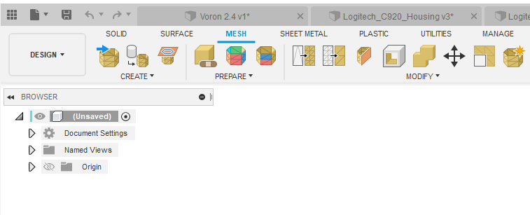
2. Navigate to the mesh environment buy clicking "MESH" on the top portion of the Fusion window. The menu along the top will change and the icons will look like the ones in the picture below.
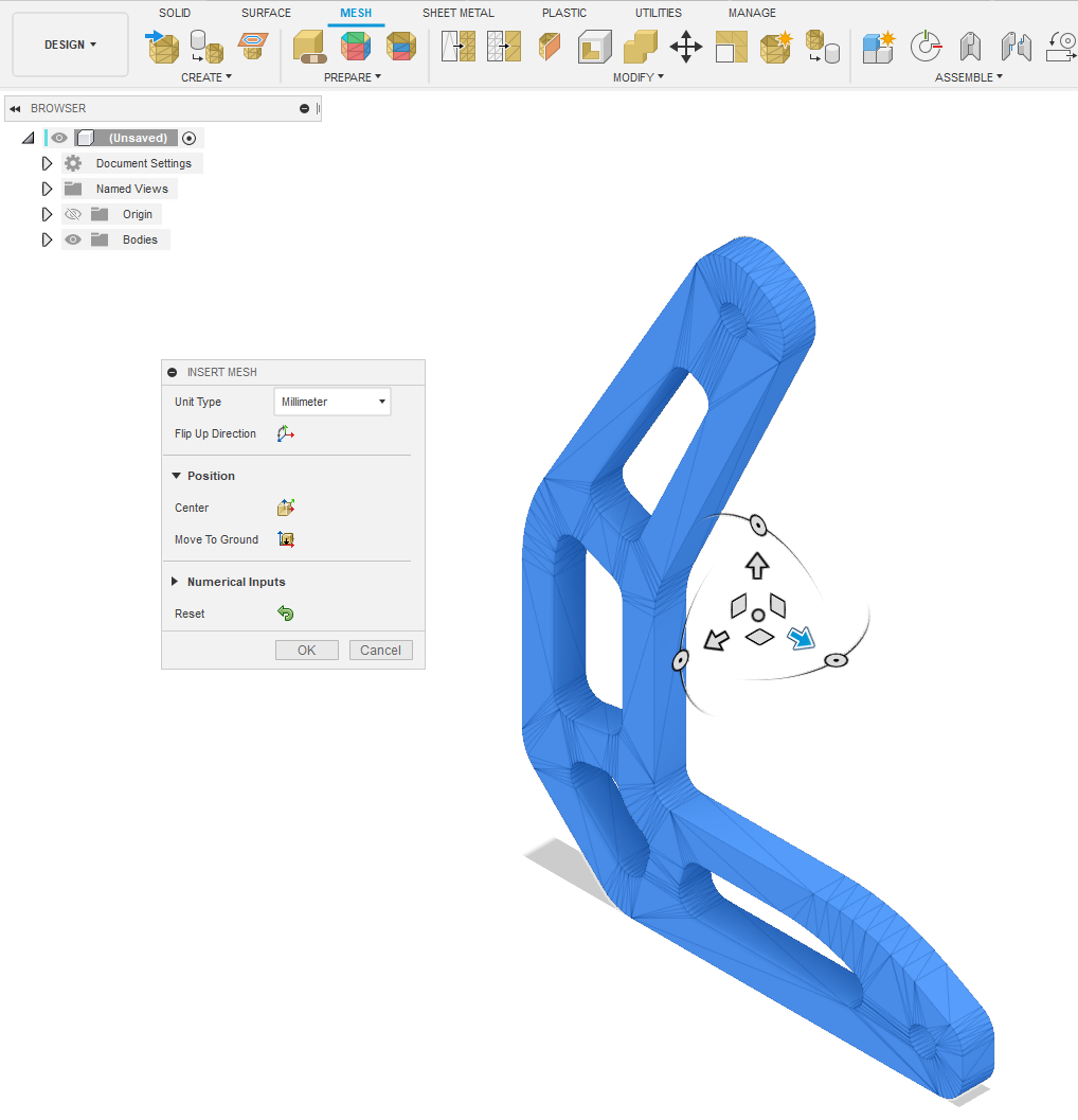
3. Fusion employs a workflow that that moves from left to right along the top of the screen. What I mean by this is that the first icon you click will be the furthest to the left and your next step will be one of the icons to the right of the first one and so on. The icons are also grouped to follow the workflow as well. Our workflow is Create -> Prepare -> Modify and it's labeled under the icons.. So let's click the "Insert Mesh" icon in the "Create" section, it's the 1st one on the left (Yellow Hexagon with blue arrow). When you do, a window will appear where you can navigate and select your mesh object (STL). Click the object, click "Open" and your mesh object will appear inside of Fusion. Fusion gives you the chance to orient, move, scale the object before you commit but, most of the time you just need to accept the default by clicking OK.
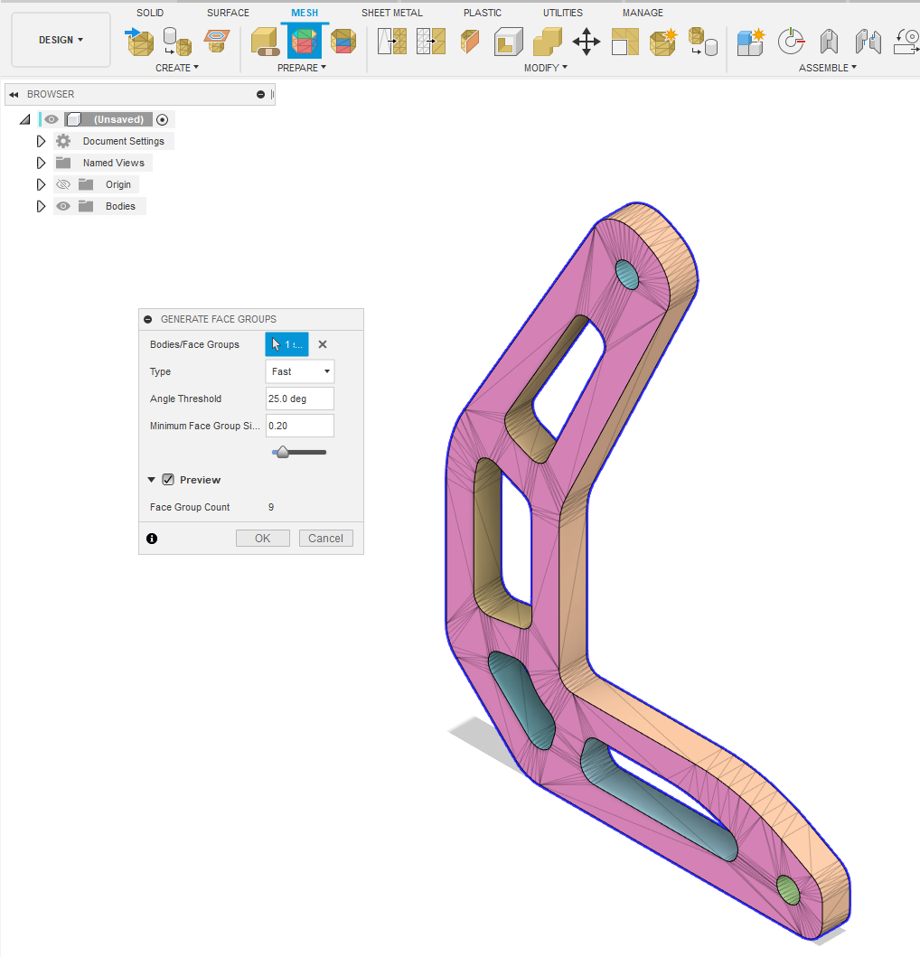
4. Next we'll create "Face Groups". Click the "Generate Face Groups" icon (above PREPARE). Select the mesh you just imported and click the "Preview" checkbox to view the mesh groups. As you can see Fusion has grouped the faces based on an angle threshold. Most of the time the default value will get you where you need to be. Of course you can modify the angle value and experiment if you don't get desired results. Basically you want discreet groups as is shown below. Where you run into trouble is when there are a lot of radii on the part and the groups start to run into each other. I'll do another tutorial on reverse engineering a part for the parts that you can't convert in the near future. So, Now that I'm satisfied with my mesh groups... Click OK to accept.
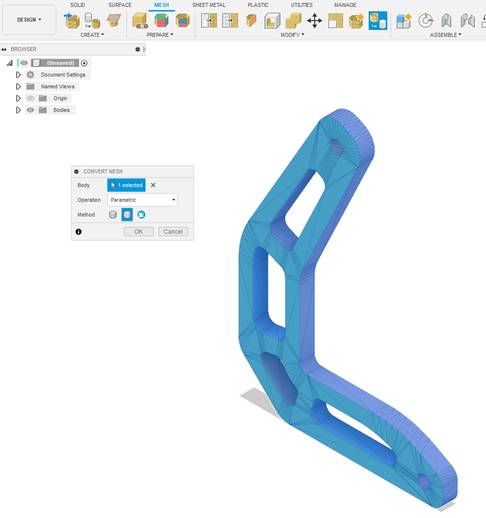
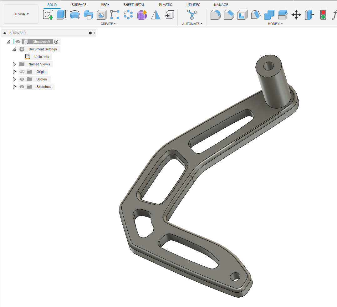
5. Next we'll convert the mesh to an editable solid. Click the "Convert Mesh" icon. It's the far right icon in the "Modify" section of the top menu. Select the mesh body. Make sure the Operation is set to Parametric and the Method is set to Prismatic. Click OK to accept and that's it! All done, easy peasy. The part will turn grey indicating that it's now an editable solid.
6. Now that we have an editable solid we leave the "MESH" environment and switch to the "SOLID" environment so that we can modify the part.
Good luck and happy creating!

Recommended Comments
Join the conversation
You can post now and register later. If you have an account, sign in now to post with your account.