

Description
Hi All,
What is Fusion 360? Fusion 360, as the name implies, it's a collection (or Fusion) of mechanical and electrical design, drafting, rendering, analysis, assembly and manufacturing software tools that together create a fully featured Computer Aided Design package that can be used to design pretty much anything you can think of. For this and subsequent tutorials we'll focus primarily on the creation and modification of 3D models that can later be printed using a 3D printer. If you don't have Fusion 360, you can download it here.
First a little background about 3D CAD modeling software. The majority of CAD modellers currently available are considered feature based solid modellers. These modellers (Fusion is one of them) allow for the creation of 3D models by adhering to the following methodology... Create a 2 dimensional reference sketch or drawing onto a planar surface, then apply a command to create a 3D feature. The basic feature types are, Extrude (in a given direction), Revolve (about some centerline), Sweep (along a path) and Loft (blend from one shape to another shape). These features can both create positive 3D objects or negative 3D objects that cut or remove geometry from existing 3D geometry. In addition to sketch driven features there are also features that can modify existing geometry such as round or bevel external edges or internal corners, etc. Feature based solid modellers let the user parametrically drive and modify the dimensions in the model creating a very powerful and flexible design tool. CAD designers generally employ one of two methods to create or design components in the context of an assembly. The first and most basic is called "bottom up design". This is where the designer creates individual parts or components and then assembles them together in an assembly. The second is "top down design". We're going to focus exclusively on Top Down Design because top down lets us model all of our components in an assembly context and lets us reference the location and edges, radii, etc. of other components so that when we make a change to the assembly... the change parametrically cascades and updates all of the parts affected by the change. With the old bottom up way, you have to hunt around and change each part and it's easy to miss something.
While my tutorial will get you started... it is by no means a full on lesson going over every aspect of Fusion 360. There are tons of YouTube video tutorials by many outstanding content creators and I encourage everyone to supplement this and future tutorials with some of those videos which do a much deeper dive into Fusion 360.
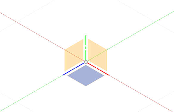
OK, let's go! In this tutorial we'll make an impossible dovetail cube.
1. Launch Fusion 360. It will automatically place you into the "Design" workspace. Across the top are commands to create and modify features along with tools to navigate around the workspace. On the left side is the "Browser" it lets you control and activate components, joints and other aspects of the assembly and lastly on the bottom of the screen is the Timeline where you can access and rearrange features. I recommend using the following as a reference Tour the Interface as it's easy to get lost in the menus.
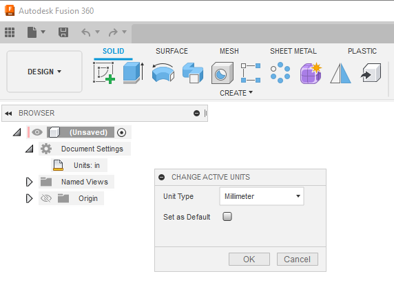
2. Set units to millimeters by expanding Document Settings and clicking Units. Select Millimeters and accept by clicking OK. If you think you're going to use millimeters most of the time then it's a good idea to set it as default or maybe you already chose it when you setup Fusion.
3. Next we'll create a sketch on a plane. The sketch icon is the first icon in the upper left corner. Pro Tip: You can hover over an icon to see what it does before clicking on it. When you click on it... 3 planes and axes will appear in the center of the work area. Select the middle one (blue).
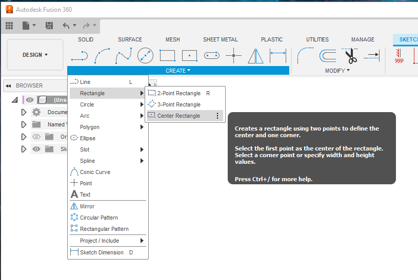
4. You'll notice that once you click on a plane the menu switches to sketch mode and the 2D sketch tools appear on the menu bar across the top. Select Create, Rectangle, Center Rectangle.
5. Click the little origin icon in the center of the workspace and drag to create a square. Just eyeball it for now. Don't worry about the size.
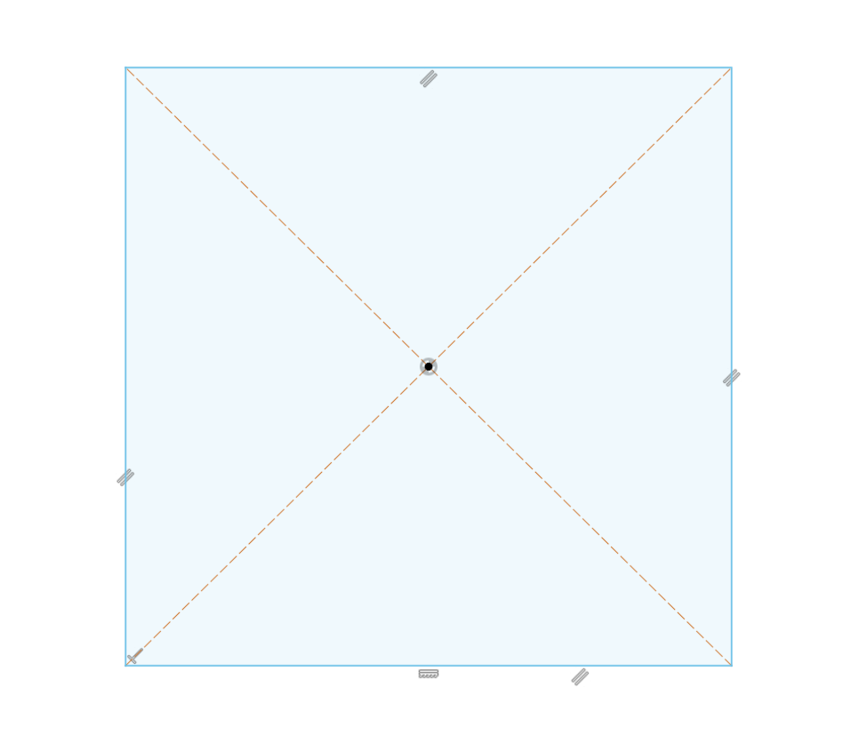
6. Next we'll add some dimensions. Before we do however, understand that while it's not required it is good practice to fully constrain your sketch geometry. When constraining geometry we must define the size and the location and/or orientation of the geometry in the sketch. When we clicked on the origin point to place the rectangle, we automatically locked or constrained the center of the rectangle to the origin of the sketch. We can see that it's constrained because the center dot is black. Light blue objects are unconstrained, black objects are constrained. When all the geometry is fully constrained, everything will be black. In addition, you can see the physical constraint symbols placed on or near the geometry. We can add or delete as many physical or dimensional constraints as needed to fully constrain the sketch.
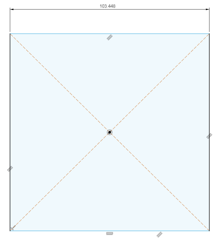
OK, enough talk, click the dimension icon (or hit the "D" key on your keyboard) in the tool bar across the top of the screen. Next click either the top or bottom horizontal line and then click to place the dimension. Once the dimension is placed hit the enter key. It should look like I have it below. Also don't worry about the dimension value at this point, we will dial that in later.
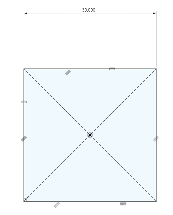
7. Next we'll add an = (equal) constraint to one of the vertical lines. We want this to be a square so all sides need to be equal and we achieve that be creating an equal constraint between one of the horizontal and vertical lines that make up the square. Click the red/black equal constraint icon near the middle of the top tool bar. Click on a horizontal line, then on a vertical line. Press escape to exit the equal constraint command. You'll notice that all of the geometry turns black and you'll also see the addition of two equal constraint symbols. While we're at it let's change the size of our 2D cube to 30mm. Double click on the dimension, change the value to 30 and hit enter to accept.
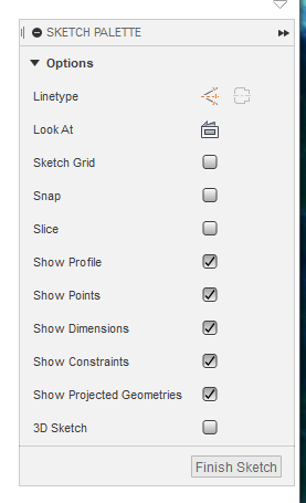
8. Exit the sketch by clicking Finish Sketch in the Sketch Palette dialog box.
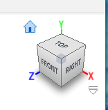
9. Activate the default 3D view by clicking home icon that appears when you move your mouse near the ViewCube in the upper right corner. You can click on any of the faces or corners of the ViewCube to change your view orientation. To zoom in or out use the scroll wheel on your mouse, click and hold down the scroll wheel while moving the mouse to spin the model. Once we have some actual 3D geometry on the screen you can try zooming and spinning the model around and you can always get back to the home 3D view by clicking the home icon.
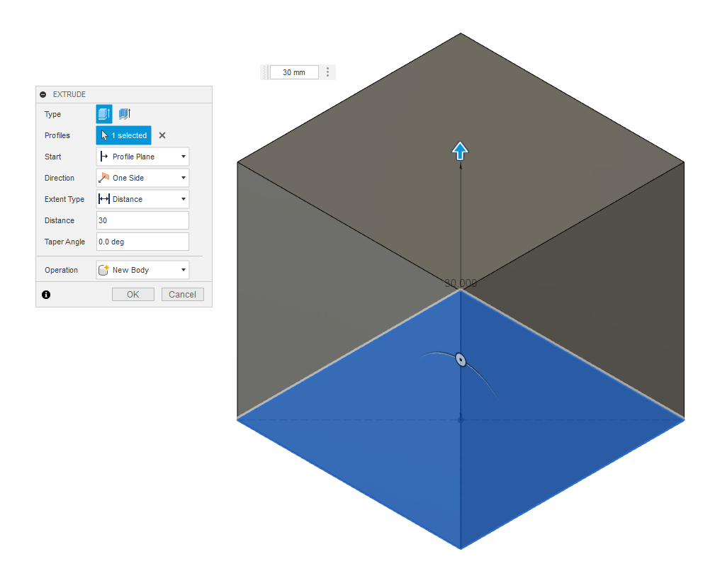
10. Next well extrude the square to create a 3D cube. Click on the extrude icon (top tool bar). When you do you'll be asked to select a profile. Profiles are enclosed regions that solid features can be created from. For this tutorial we're only creating one feature (shape) from a single profile but... you can create multiple features (shapes) from the same sketch if you want. in addition, there are a multitude of options when creating extruded features and the extrude command can either create, cut or join other features but... For now we're keeping it simple. Select the 30mm square profile and enter 30 for the distance. Once you have accept by clicking OK. Congrats! You have just modelled a 30mm cube.
11. Now is a good time to save your work. Click on the save icon, give it a name and click OK.
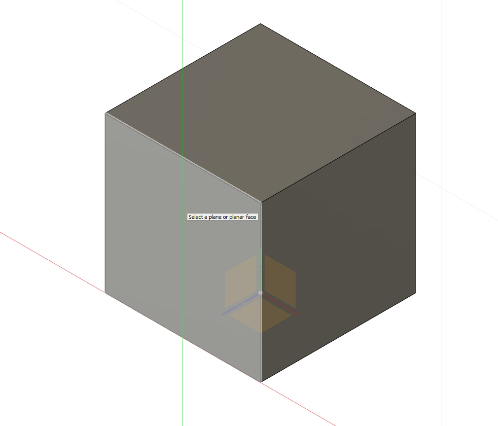
12. Next we're going to create another sketch but this time it will be on the face of an object. Select Sketch and click on the left side face of the cube.
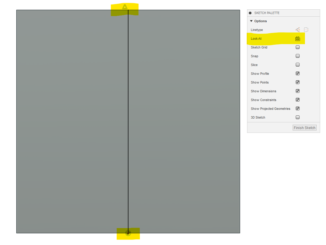
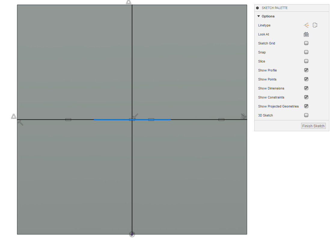
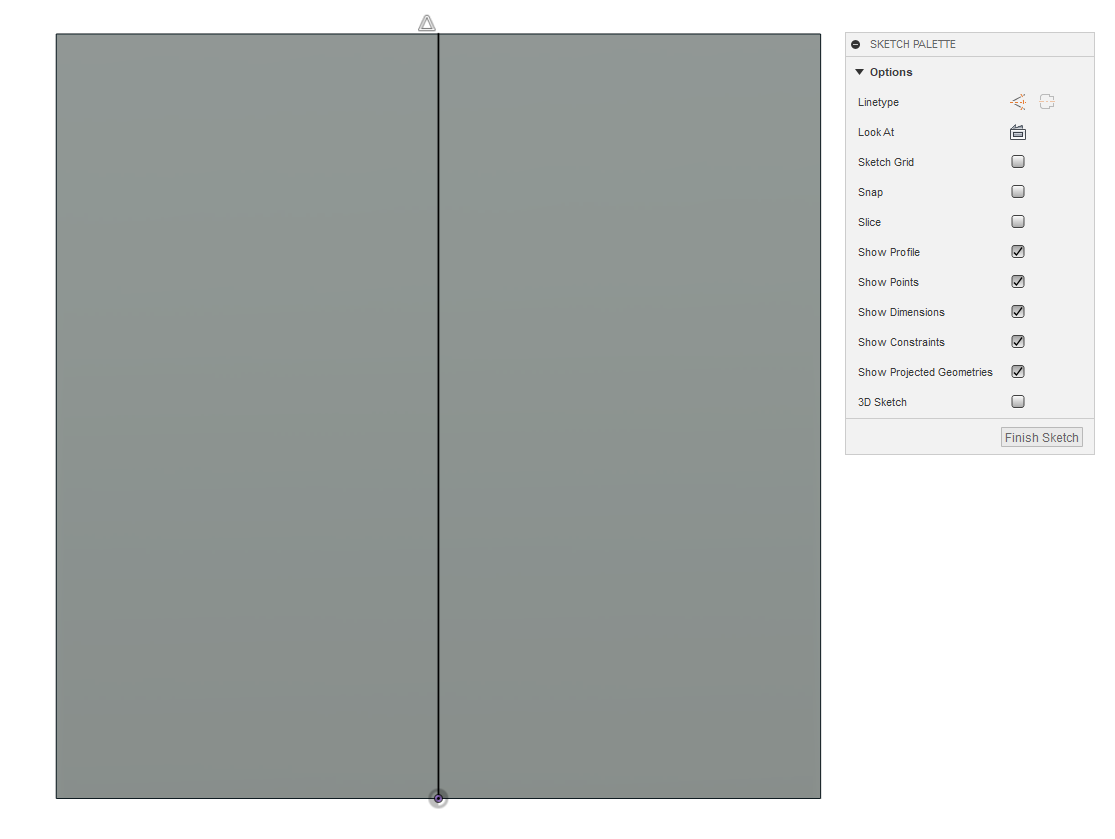
13. You should now be looking at the flat face of the cube that you selected, if not click "Look At" in the Sketch Palette. Select Line from the sketch menu on top and connect one end of the line to the middle bottom of the square and the middle of the top. You will notice that the line wants to snap to the middle, edges and corners of the existing geometry of the cube. This is exactly what we want the line to do because this line will end up being our vertical centerline thru the middle of one side of the cube. I'll be highlighting areas of interest as we go along.
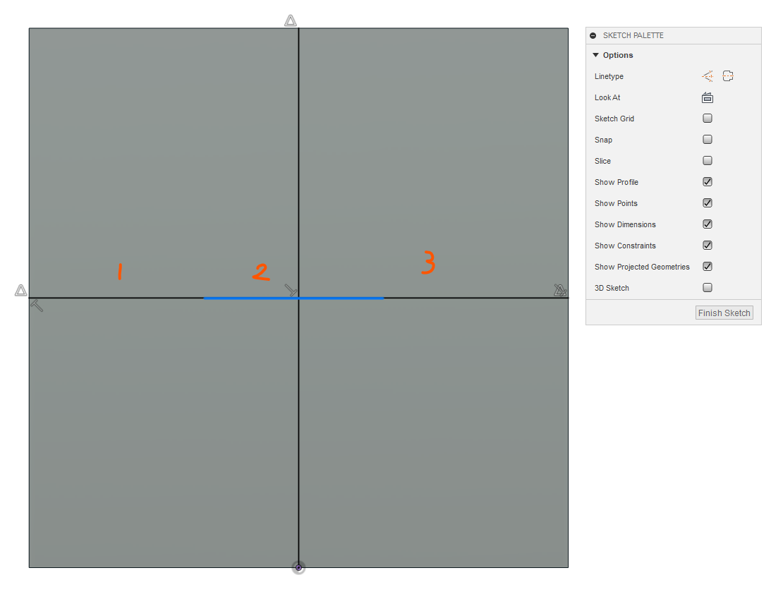
14. Next we'll draw 3 connected lines horizontally across the middle of the cube. I've numbered the 3 line segments, the center one is highlighted in blue. Ensure that the lines go from the mid point (triangle symbol) on one side to the mid point of the other side. I know this sounds weird but it will make sense in the next step.
15. Now we'll make the 3 lines equal by selecting the equal icon from the constraints menu at the top and clicking the left line and the middle line. Next click the right line and the middle line. Now all 3 lines are equal to one another.
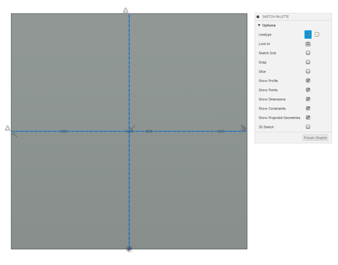
16. Next we'll convert the sketch lines in construction lines. Construction lines are reference lines that are ignored when making features. Select all of the vertical and horizontal sketch lines and then click the construction icon in the Sketch Palette.
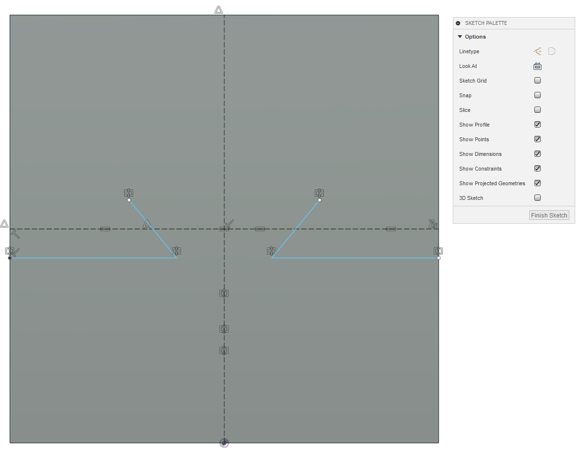
17. Now sketch two lines as shown. Just eyeball the location for now.
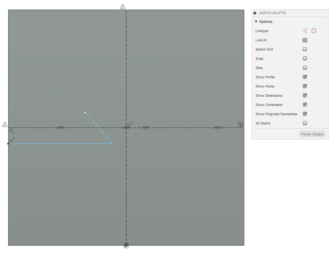
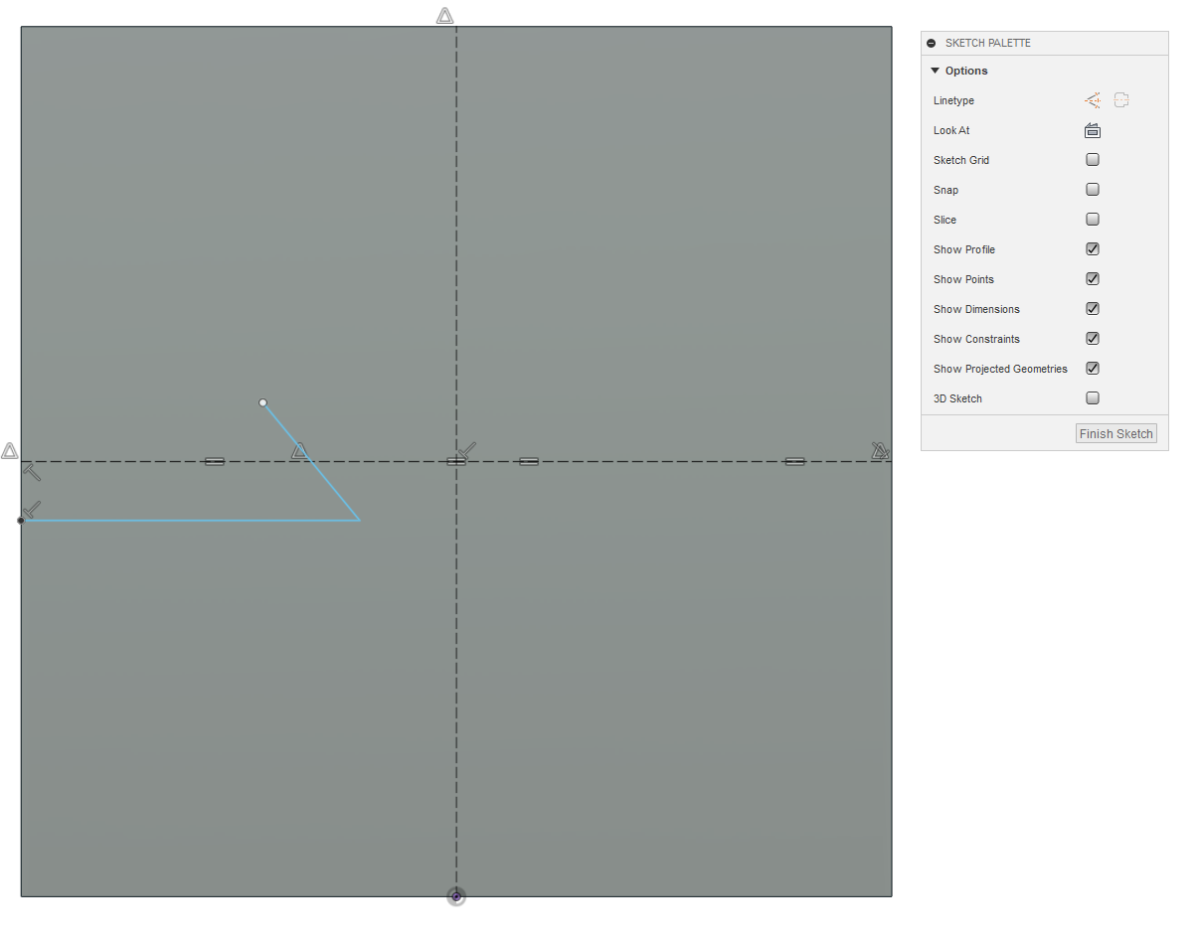
18. Now we're going to create a midpoint constraint between the midpoint of the angled line and the left endpoint of the middle horizontal construction line. Select the Midpoint constraint from the constraints menu at the top of the screen. Click near the midpoint of the angled line and then the left endpoint of the middle construction line endpoint. Once you do you'll see the triangular midpoint symbol.
19. Next we'll mirror the two lines over to the right using the vertical construction line as our mirror line. Select mirror from the top menu. Select the horizontal and angle lines as your objects to be mirrored and then select the vertical construction line as your mirror line. Click OK to accept.
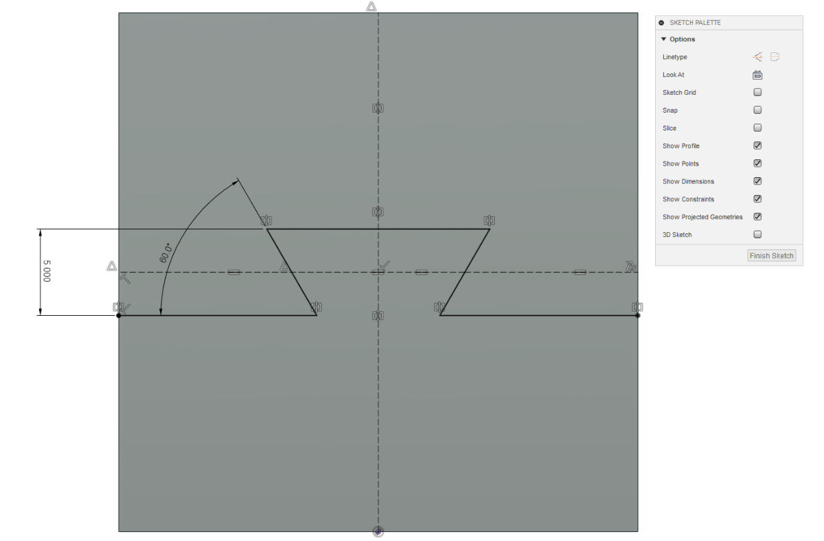
20. Create a line between the two angled lines as shown. Next select the dimension command and create two dimensions. One vertical dimension and one angular, click the horizontal line and angled line to create the angular dimension. Modify the dimensions to 5mm for the vertical and 60 degrees for the angular. As you can see, we only need two dimensions to constrain and control this sketch because the mirror command automatically creates symmetric constraints between the right and left sides. In addition, the 3 equal construction lines maintain equal proportions of the dovetail. We could delete the center equal constraint and add a horizontal dimension in it's place to make it variable. Click Finish Sketch.
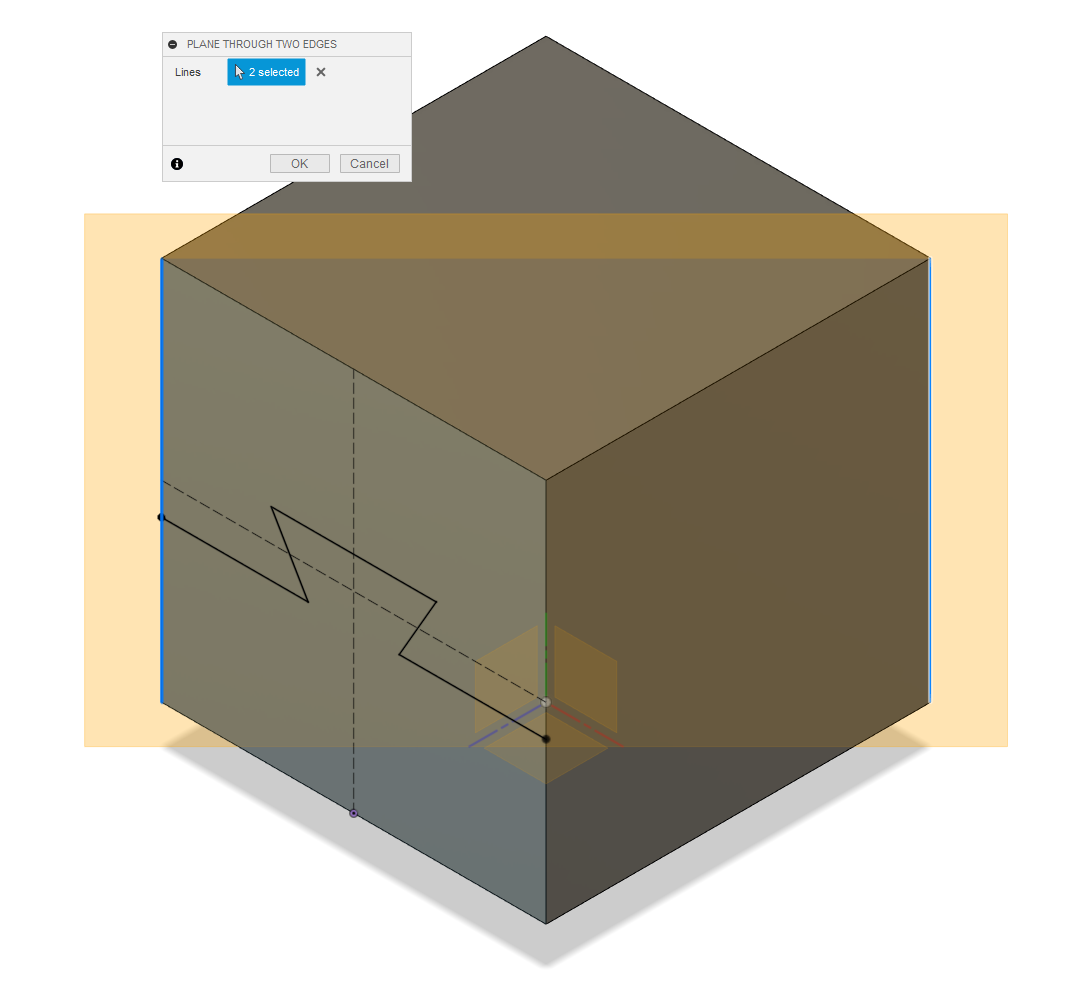
21. Now we'll create a construction plane. Click the home button by the viewcube. Now select the "Plane through two edges" command and click the two vertical edges of the cube. If your screen looks like mine click OK
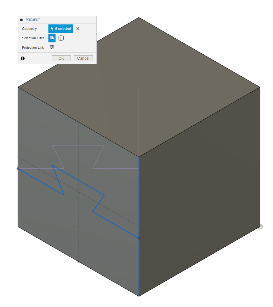
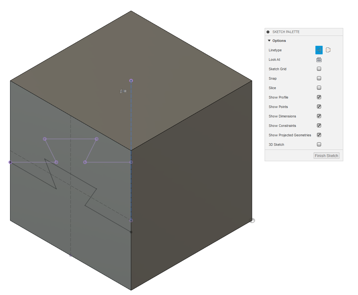
22. Next we'll create another sketch on the plane that we just created. Click the sketch icon and then click on the plane we just created. Make sure your in a 3D view when you do this to help illustrate what we trying to achieve. The impossible dovetail works because we've rotated the cutting plane 45 degrees. You'll see... We'll now use the project command to project the lines from the previous sketch onto this sketch. Select the project command from the create menu at the top of just hit the letter "p" on the keyboard. Select the lines highlighted blue and click OK to accept.
23. Next well turn the vertical projected line into a center line. Select the vertical line and then select centerline on the Sketch Palette.
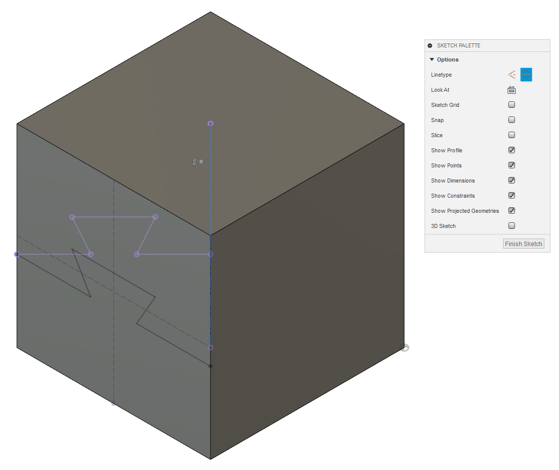
24. OK, Now let's mirror the projected lines on the left, over to the right. This should be a walk in the park. Just like we did before. Select the mirror icon, then select the projected lines on the left and since we converted the vertical line into a centerline... Fusion automatically selected it for us. Select OK to accept. We can now exit the sketch.
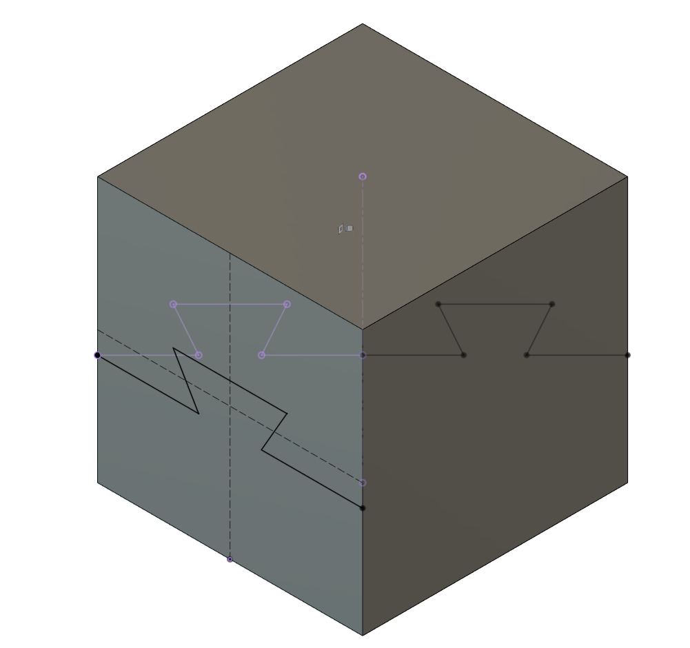
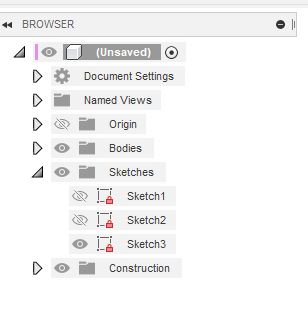
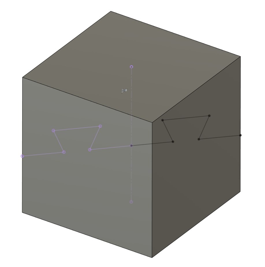
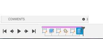
25. OK we're finally at the home stretch. Let's do a little housekeeping first though. Expand "Sketches" in the browser on the upper left. Then click the eye symbol next to sketch2. Clicking the eye is like a light switch. It doesn't delete or disable the sketch, it just toggles it's visibility, the same is true for any item in the browser you can show or hide objects any time. Now your cube should look like mine.
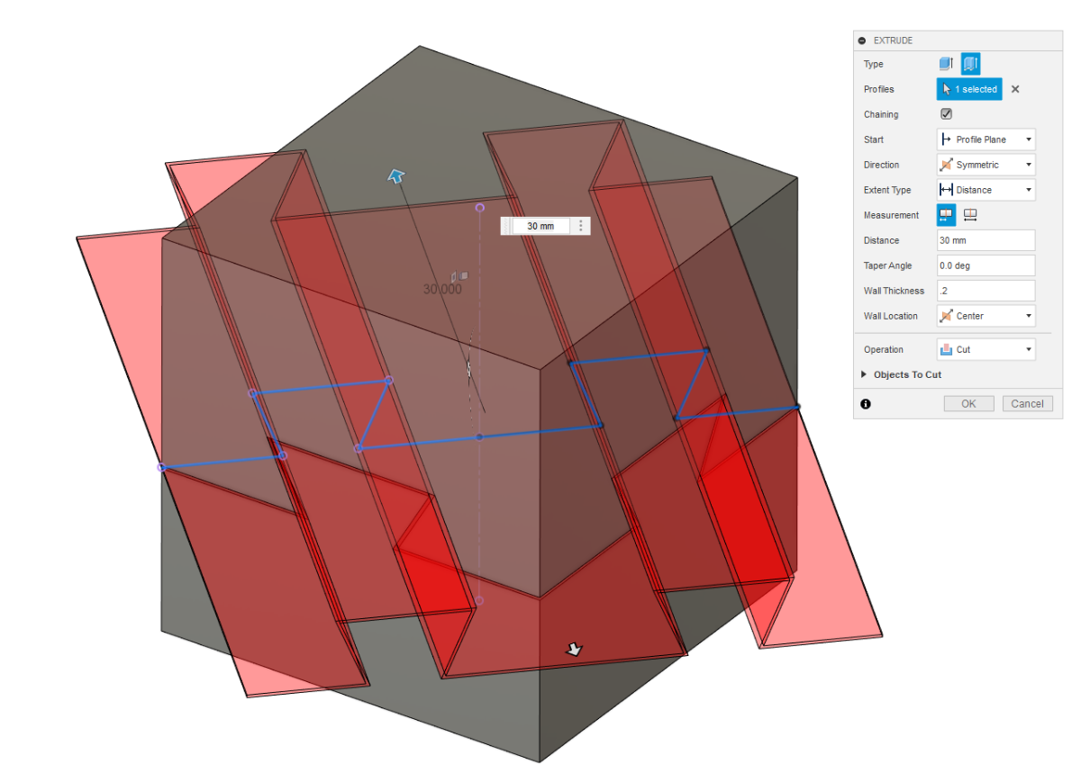
26. Let's get to cuttin'!!! Select the extrude command from the top menu to bring up the extrude dialog box. At the top of the box select the Thin Feature icon and select the lines from our last sketch. In the extrude dialog make sure the "Direction " is set to symmetric, "Distance" is 30mm, "Wall Thickness" is .2mm and Wall Location" is set to center. Click OK to accept.
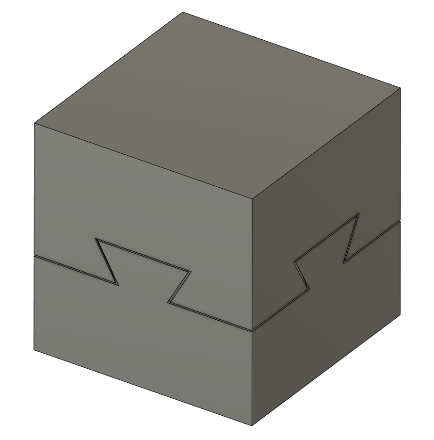
27. Congratulations! We now have two solid bodies that we can 3D print.
28. Before I go... Let me show you how to save the bodies as STL files for printing and a couple other tips.
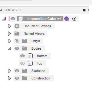
Remember, you can hide/show object by clicking on the eye icon in the browser. You can also rename the bodies by clicking twice.
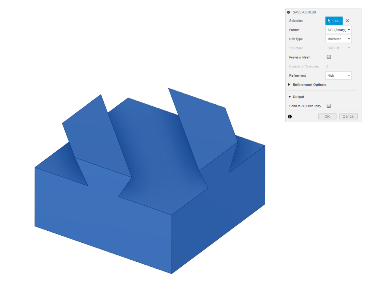
Right clicking on one of the bodies brings up a menu. Select "Save as Mesh" to open a dialog where you can configure and save one or both bodies as an STL or 3MF file.
Lastly... Every dimension can be changed by right clicking the feature icons on the timeline at the bottom. If, after you print the two halves and they're too loose... right click on the last extrude feature and edit it. The dialog will come up and you can change the thickness from .2mm to .1mm or any number you wish. Experiment, explore and have fun.


Recommended Comments
Join the conversation
You can post now and register later. If you have an account, sign in now to post with your account.