Leaderboard


Popular Content
Showing content with the highest reputation since 08/27/2021 in File Comments
-
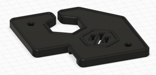
 Success! Its amazing what you can do when you can see now that my magnifiers came in. Tweezers also helped get the neo pixels in place. Then it was just a matter of fine tuning the sanding on the side of the board. The jig below worked great to set the wire length. It is the inverse image of the slots on the tool head. Here is the jig file if anyone wants to try it out. Neo Pixel Soldering Jig.3mf6 points
 -
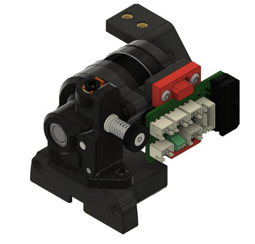
As promised, here are the new parts for mounting an umbilical PCB as well as two cable_door versions with a cutout for the filament release lever. I have also changed the release lever slightly to give it a greater range of movement. The shorter idler_arm is also finished and included. Cable_Door_Orb2.0_Fil_rel_lever_v1.1.stl Cable_Door_Orb2.0_Fil_rel_lever_Fil_sensor_v1.1.stl Orbiter_2.0_Motor_Bridge_Umbilical_PCB.stl Orbiter_2.0_Umbilical_PCB_Mount.stl Orbiter_2.0_Filament_Release_Lever_v1.2.stl Orbiter_2.0_Idler_Arm_Short_test_1.1.stl5 points
-
The search box has a dropdown where you can select what to search in. I get 14 results on Boop for this comment thread.5 points
-
I worked this up using geometry from the Euclid GitHub page. It should work with the M2.5 self-tapping screws from the kit. x_frame_Mini_Stealth_Euclid_left.stl x_frame_Mini_Stealth_Euclid_right.stl5 points
-
3 holes uploaded5 points
-
Got my first Voron serial number today for my V0.2. This frame was what was printing for my serial number video. Started assembling it tonight. Let the modding begin!4 points
-
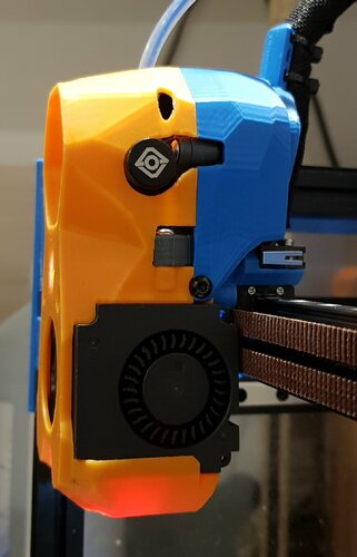
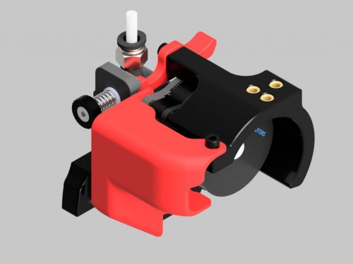
I just finished assembly, the beta 4 carriage is also installed and feels great one set of heatsets is a bit difficult to get to but works. Other then that it seems to look great. Here are some Pictures of the finished toolhead4 points
-
Nice thanks good job4 points
-
with the 4mm infill it works perfectly! so you need the 3mm difference on the center station if you already took 1mm off of the SBmount. nothing like the reward after a hard day work.... oh wait... WORK! I knew I forgot something...4 points
-
Hi! Just found out about this website and that my mod is hosted here. I'll attach the files of the cable duct on this post. Just keep in mind, that it is a very crude model I made only for myself and is limited to a 350mm build. rear_cable_duct_lower.stl rear_cable_duct_upper.stl4 points
-
I created modified ones here: https://github.com/silverbp/voron-2.4-parts to account for the 2.4r2 3mm gap, it just goes around the rails. I also recessed the screws so you could use an m3 x 6 screw, an m3 x 8 will work too, but it bottoms out right as it gets tight. If I knew how to make the entire thing thicker, I would have done that by a mm which would have solved the m3 x 8 bottoming out... that's beyond the scope of what I know how to do in fusion 360 with the beveled edges there. Actually I found the step file, figured out how to remove the edge, now it's 1 mm thicker, so a thicker usb cable can get through and this also gives more room to sink a 8mm m3 screw.4 points
-
So I've been trying a few different ways to mount the HartK stealthburner PCB with this mount. I modified the Orbiter_v2_Motor_Cover.stl from here on TinkerCad and integrated the pcb_spacer.stl from HartK's repo. It's far from elegant as I don't know CAD that well, but I printed it and it seems to be working well, so it may be good enough for someone with CAD knowledge to take the idea and run with it. The parts I printed that are shown in the pictures are sneakytreesnake's front and rear mods, z00mantwo's cable cover mod and the Orbiter_v2_Chain_Anchor_Igus.stl from spacelab's folder here last updated on May 21. The PCB side of this stl screws directly into the motor with a heatset insert. The other side of the motor screws through the Rear part from sneakytreesnake and screws directly into plastic. Honestly I thought I had added a hole for a heatset insert on both sides, but when I printed it I realized I must not have grouped that hole with the object in TinkerCad so there wasn't enough space for a heatset and it seems to be fine. Orbiter2-motor_cover_PCB_mod.stl4 points
-
V2 Afterburner Update I've added the next revision v2, which adds fixes a few issues with fitment on the afterburner toolhead. I had to slice the back of the fan to get the V2 to sit just right and for printability of the afterburner fan shroud. This should be tested to ensure it fits properly and doesn't interact with the fan too much. There potentially could be a few problems with this setup but it's one of the best solutions I could come up with that didn't modify the afterburner fan too much. V2 Stealthburner update I've added the stealthburner mount for the v2 as well. The V2 is so far forward that it requires a ton of work to get it to fit properly. This version was printed and semi tested but I need others to verify if it actually works on their stealthburner. I think I've included all the necessary parts to make this work but if you find something missing, please let me know and I'll add it to the repo. *Also, each version is now hopefully compatible with the ERCF.4 points
-
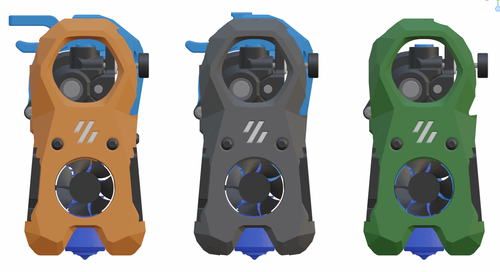
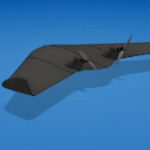
Hi all, I am the original author of this orbiter mount. I have a v2 currently in alpha for testing. I will release the latest version to the github soon. I have a few issues to work out and I will release it as a stable build. I've attached some images of the current design.4 points
-
I am currently working on exporting the 428 .stl files. 222 different shroud pieces (including CropTop versions) 5*12 (60) different core pieces 7*4 (28) x-frame sets 4 V0 x-carriages 4 V0.1/V0.2 XY_joint_upper replacements 5 Printers for Ants x-carriage parts 3 DAB parts 4 probe mounting pieces 11 different cable doors 7*9 (63) motor bridge and umbilical PCB mounts 4 status LED parts and Knomi2 clip 4 filament release levers 10 customized extruder parts I will upload them and then I need to make new instructions although the v2 is much easier to install than the current version. I'm not sure how quickly I will be able to finish (and I will be away the week after next) but I plan on making an announcement post that will also outline the changes.3 points
-
Here you go. Mini Stealth - Orbiter 2.0 + filament sensor + Bambu hotend + ZeroClick mount point but with the regular top opening. [a]_Mini_Stealth_Orb_2.0_FilSensor_Bambu_ZeroClick_v1.1.stl3 points
-
Here is a new Umbilical/EBB36 mount with the vertical back. Umbilical-Mount-LGX_Lite_EBB36.stl3 points
-
3010 works well. U have to use the cables in a longer version and lay it around the Hotend. It works and maintenance is more easy. I also use the Winsinn 3010 blower.3 points
-
had no issues getting the inserts in , used a screw with the insert just snapped in to the first thread, heated with the flat soldering tip and pulled it in with the screw without problems, the M3x12 fits perfect, many thanks!!3 points
-
Will this work? x_frame_Mini_Stealth_left_Beacon_zip-ties.stl3 points
-
As a welcome side effect, the max. accelerations with the miniSB are much higher than with the standard one. Great work!3 points
-
The 3D model from Beacon3D included geometry for the metal exclusion zone as well as the sensing zone and I used this to locate the mounting studs. The PCB is 1.6mm thick. Glad it works and happy to help! "Sorry, the number you have reached is no longer in service. If you feel that you have reached this recording in error, please hang up and dial again..."3 points
-
Having an extra place for some of the wires to go would be nice but with different extruders above the different hotends it would be very hard to find a safe place to have the wires come out through the top. I want to keep the design as universal as possible. If the strength and the routing for a Revo with a LGX Lite is different than a Revo with a Mini Sherpa then the design starts branching too much and gets very difficult to maintain. I think that the change I am trying to push right now will make a good difference. Also, I think you will be pleasantly surprised with the Mini Sherpa and the x-frame pieces. I've only had to print these parts once and it worked well enough since I designed it around the fans that I have.. I really should make a little more room for fans from different suppliers. Adding screws at the bottom would help with rigidity but then I would need to maintain 28 more shroud versions. This brings to mind wise words from @Penatr8tor, 'is better the enemy of good enough?' The V2.4/Trident x-frame will be more rigid than any of the V0.1/V0.2 x-carriage pieces. Is it necessary that the Mini Stealth is as rigid as the full size Stealthburner?3 points
-
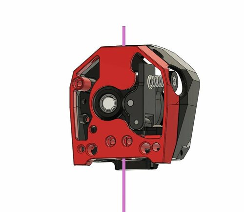
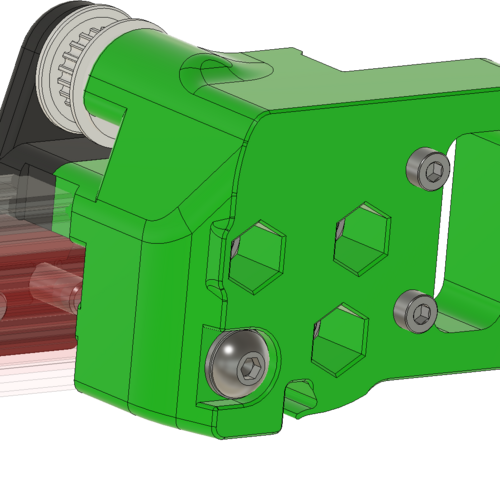
Yes, I moved the insert to the back of the x-carriage. When trying to add strength to the system, it is only as strong as the weakest part. The area with the green rectangle is in compression and the screw creates the strength. Unless this material is getting crushed when installed, there is little that could be done to add strength here. Increasing the mating faces at the cyan rectangles could help counter the bending moment caused when applying force at the nozzle. The magenta oval is the weakest area and the layers are not going in the best direction (but this would be very hard to change). The Orbiter extruders are the worst at this area because the stepper motor sits so low while the Mini Sherpa allows the best cross sectional area here. I hope I don't need to add the screwdriver in this illustration3 points
-
Thanks, I do what I can.. I have worked up a new version that should work with either of the Mini Stealth Orbiter toolheads. They raise the nozzle by 3mm so I don't know if the Switchwire has enough negative Z travel for this to work. x_frame_Switchwire_Orbiter_right.stl x_frame_Switchwire_Orbiter_left.stl3 points
-
It really has come a long way from my first design.. Thanks to you GOMs for beta-testing the early design issues!3 points
-
I love how this product just keeps evolving. I printed one of the first models that came out and it is working beautifully on mysecond V0. I think on behalf of the teamfdm community, I would like to give a BIG shout out to @atrushing for his great work, willingness to adapt his models to suit the need of individual users, speedy response to specific requests and his help in general in this forum. Thank you3 points
-
That would be a good idea but the way the fan is held in place means that the 3007 fan would barely be supported when using the spacer. Extending the bottom shelf part would make it hard to tilt the fan into position. Plus, I think that having the fan recessed so far back from the front would look a little strange. I think I can adjust the top section and maybe use a break-off part that would allow the 3010 fan to fit. It will take a little while because I will have to modify the geometry on at least 35 different toolheads but I am working on it.3 points
-
I have updated the motor_bridge and added an Umbilical_mount in the Downloads section.3 points
-
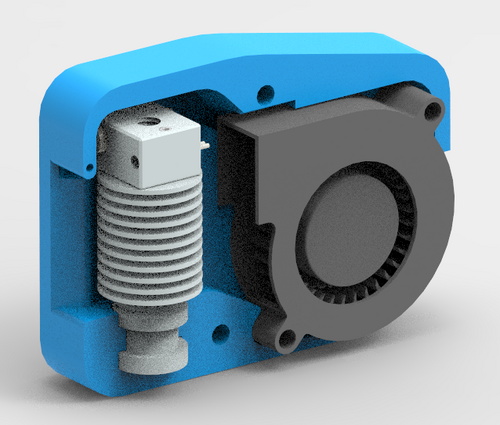
I've been using it for a long time. An excellent design. Cooling is great.3 points
-
I ran out of reactions for the day.. Thanks for the kind words!3 points
-
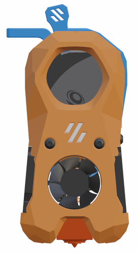
Thanks for the compliment! Here is a basic BOM for the Mini SB Orbiter 2.0: 1 x hotend (Heat me up Scotty!) 1 x extruder (Push it real good!) 2 x 4010 blower fan 24V (part cooling) 1 x 3007 fan 5V (hotend fan) 3 x SK6812 WS2812B RGBW - single LED PCB 5 x M3x4x5 heat set inserts (3 for toolhead and 2 for x-carriage) 3 x M2.5x6 screws (hotend mounting) [M3x6 for Revo Voron] 1 x 4mm OD 2mm ID PTFE tube 4 x M3x8 BHCS (secure extruder and cable_strain_relief) 1 x M3x10 BHCS (cable_door pivot) 1 x M3x6 (secure cable_door) 2 x M3x35 BHCS (secure toolhead to x-carriage) Here is a mockup of how the Mini SB would sit on the Ender 6 carriage to maintain the same Z distance to the build plate: The top of the Mini SB is 20mm higher than the metal plate. It would also sit at least 15mm further forward than the stock hotend. I don't know if that would affect the Y travel or if the build plate could be adjusted to maintain the same build volume. The green body is a model I found for using the Orbiter 1.5 on the Ender 6.3 points
-
Here is what I've come up with. With a M2x10 screw it holds very well. I don't know how much force the magnets apply while docking the probe, but the glue (hot or super) might not even be needed. When I get some time, I will re-work the shroud to fit the second screw. For now, I hope this lets you get your build finished. ZeroClick_Mount_Mini_Stlb.stl3 points
-
I redesigned the Roller so that it can be more easily printed. There are 2 files, Bearing Shaft (you'll need to print two of them) and the roller. Print using Voron standard settings. I opted to use gyroid infill as the nozzle doesn't cross over already printed lines (like cubic) that can potentially knock the tall vertical roller off of the bed. Files are attached in a zip file. Roller_Redesigned_02.zip3 points
-
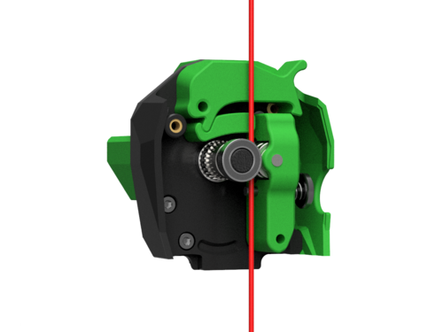
Just a note for those that take their gears out of an afterburner galileo mod into this one: The gears have switched sides! that means you need to invert your direction `dir_pin` in your klipper extruder settings [extruder] dir_pin: !PD6 # The is inverted now3 points
-
Is 40w or so going to heat the chamber enough? I think it will certainly help. On a Voron 0 the heated bed alone dumps 60w of heat into the chamber during warmup in addition to the heat from the hotend. Of course both the bed and hotend have their power reduced when they attain the target temperature while this heater could be controlled separately.. I see one potential weakness in the design: Hotends are designed specifically to prevent heat from the heater block from migrating to the heatsink, while here you would want to maximize this effect. Perhaps a solid brass or copper bolt could replace the heatbreak? As the V6 has an uncommon 7mm thread in the heatsink, perhaps an older V5 type heatsink with the 6mm thread (same as the heater block) could be used with a brass 6mm bolt. The next question would be if the heatsink could dissipate 40w of heat without melting the housing... it was only meant to dissipate the heat that creeps past the heatbreak. Perhaps a smaller heater element should be used. And finally, to regulate this could be tricky. You ultimately want to regulate the chamber temperature but running this heater without some kind of sensor on the heater could be disastrous if the fan were to fail. Perhaps a thermal fuse could be attached? Good luck!3 points
-
Is there a possibility you can make it compatable with the ercf? Really love this extruder and I just finished the ercf and would love to use it with this design3 points
-
Galileo with Stealthburner mod.3 points
-
Would there be any chance for you to make one for orbiter 2.0? Cheers3 points
-
I uploaded the generic chain anchor for the three hole versions.3 points
-
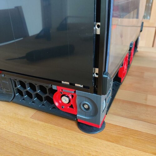
Here's my config as a reference. My 'verify_heater' values are extreme because of my big glass enclosure. ##################################################################### # Chamber heater ##################################################################### [heater_generic CHAMBER_HEATER] gcode_id: C # The id to use when reporting the temperature in the M105 command. # This parameter must be provided. heater_pin: PB10 max_power: 0.750 sensor_type: Generic 3950 sensor_pin: PF7 smooth_time:1.0 control: pid # Control algorithm either pid or watermark (bangbang) #pid_Kp: 25 #pid_Ki: 1 #pid_Kd: 900 pid_Kp=35 pid_Ki=1 pid_Kd=350 #max_delta: 0.25 # On 'watermark' controlled heaters this is the number of degrees in # Celsius above the target temperature before disabling the heater # as well as the number of degrees below the target before # re-enabling the heater. pwm_cycle_time: 0.016666 min_temp: 0 max_temp: 110 [verify_heater CHAMBER_HEATER] max_error: 20000 # every second, if temp is beyond hysterisis below, the counter will add the error untill the 'max_error' is reached check_gain_time: 600 hysteresis: 5 heating_gain: 1 [idle_timeout] #gcode: ## A list of G-Code commands to execute on an idle timeout. default is to run "TURN_OFF_HEATERS" and "M84". timeout: 10800 ## Idle time (in seconds) to wait before running the above G-Code default is 600 seconds [gcode_macro M141] ##Chamber Heater ON -- gcode: SET_HEATER_TEMPERATURE HEATER=CHAMBER_HEATER TARGET={ params.S } ***NOTICE the gcode_macro M141 part --> this is because Klipper has no native support for M141 (set chamber temp) command !! custom Start G-code from my SuperSlicer: M141 S[chamber_temperature] M140 S[first_layer_bed_temperature] M104 S[first_layer_temperature] ; M109 S0 ; uncomment to remove set&wait temp gcode added automatically after this start gcode print_start EXTRUDER={first_layer_temperature[initial_extruder] + extruder_temperature_offset[initial_extruder]} BED=[first_layer_bed_temperature] CHAMBER=[chamber_temperature] g0 x170 y170 z25 f8000 Typical header of my G-code files: M141 S35 M140 S55 M104 S190 print_start EXTRUDER=190 BED=55 CHAMBER=35 g0 x170 y170 z25 f8000 M107 G21 ; set units to millimeters G90 ; use absolute coordinates M83 ; use relative distances for extrusion3 points
-
I will save your first question for last.. 2. I never designed a backplate to fit this onto a Prusa MK3 but it would be a fun exercise. To get the extruder motor above the LM8UU bearings, you would need to raise the nozzle up by at least 10mm and I think it would help to switch the double bearings to the bottom so that you could make the top section more narrow. (yes, I already had a mockup of the MK3s toolhead in Blender ) 3. If you would like quick hotend swaps, the Bambu hotend is the only one that could be removed (by removing two screws from the side) without first removing the extruder. The rest of the compatible hotends are held on by screws from above or behind the core piece. 4. If you are looking for high flow on a budget, I have heard that the Dragon Ace hotend is pretty good. I have a CHC TD6S on my Trident and can print at up to 200mm/sec with it. The Bambu hotend is quite respectable as well as cost friendly and would allow you to remove/swap it quicker. The Mini Stealth cannot fit a V6 style hotend with the groove mount. That style is just too tall. 1. Most of the .stl files you would need are in the Sherpa Mini folder under the main Extruders folder. You would need to pick the core piece that fits your choice of hotend. The shroud would probably use a 3010 hotend fan under the probe_left or right folder you would use the first option unless you wanted to use a Knomi display on your toolhead. If you can fit the Pinda to the Prusa-style backplate then you could use a standard shroud You would need the motor bridge and PCB mount for the EBB36 as well as the cable door The Common Parts folder has the rest of the components you would need such as: the Pinda side mount bracket the blower air guide x2 and the gluing tool the status LED carrier and diffuser you can also use the white-only LEDs by Timmit if you don't have RGB control for the NeoPixel LEDs.2 points
-
Glad to help and that there is an x-carriage version that will work for your printer! I wonder if I should (or even can) make versions for MGN12C and MGN9C linear carriages.. The wedge was a fun solution. It took a while of staring at the 3D model trying to imagine how to fit clamp blocks and screws before I figured it out. I have a paypal.me link and would greatly appreciate any support!2 points
-
This is fantastic. I've printed a few in a few different colors, and recently started dressing one up with its furniture. Those 4010 blowers fit like a dream! Outstanding work. I'm currently drafting up an X-mount for a front-facing MGN12 with horizontally-oriented 6mm 2GT (Ender 3 style). I'll post it up if it works out2 points
-
Printed test parts with the correct offset work! Everything lines up and my printer has belts for the first time. I just need to make one small edit to the wall chamfer to give a little more room for perimeters near one of the hex nuts.2 points
-
For anyone wondering how to get this working when you already have the Ellis bedfans.cfg: In the bedfans.cfg change the [gcode_macro SET_HEATER_TEMPERATURE] as such: [gcode_macro SET_HEATER_TEMPERATURE] rename_existing: _SET_HEATER_TEMPERATURE gcode: # Parameters {% set HEATER = params.HEATER|default("None") %} {% set TARGET = params.TARGET|default(0)|int %} # Vars {% set THRESHOLD = printer["gcode_macro _BEDFANVARS"].threshold|int %} {% if HEATER|lower == "extruder" %} M104 S{TARGET} {% elif HEATER|lower == "heater_bed" %} M99140 S{TARGET} {% elif HEATER|lower == "chamber_heater" %} _SET_HEATER_TEMPERATURE HEATER=chamber_heater TARGET={TARGET} {% else %} {action_respond_info("Heater %s not supported" % HEATER)} {% endif %} # Set fans to low if heater_bed temp is requested above threshold temp, and kick off monitoring loop. {% if HEATER|lower == "heater_bed" %} {% if TARGET >= THRESHOLD %} BEDFANSSLOW UPDATE_DELAYED_GCODE ID=bedfanloop DURATION=1 {% else %} BEDFANSOFF UPDATE_DELAYED_GCODE ID=bedfanloop DURATION=0 # Cancel bed fan loop if it's running {% endif %} {% endif %} Basically you have define your new heater. You set the temperature in that definition with _SET_HEATER_TEMPERATURE HEATER because that is what the original macro is renamed to. I will admit it took me far too long to figure out how to make this work.2 points
-
Good point. It would just be a little tedious re-uploading all of the parts and trying not to make any mistakes. When I get the LGX Lite uploaded I'll start going back through the Orb1.5/2.0 files.2 points
-
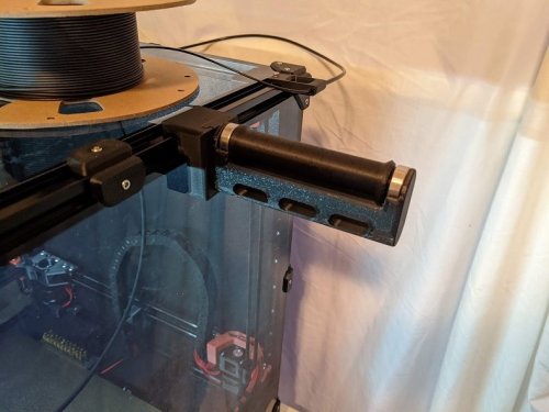
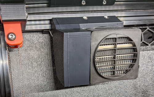
My last filter without stealth has no canbus wiring. At some point I will make an minimalistic industrial Version of this filter. Now I am working on adding a heater to it Fanny_Pack_heater.7z2 points
-
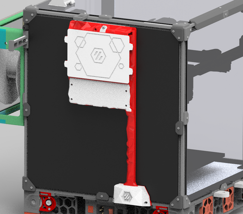
I've printed the mount for the stealth burner and ran into a few fitment issues. I am running the latest stealth burner beta as of 20 MAY 2022. Fitment issues: 1) On the back end of the mount, there is interference between the edge of the orbiter motor, and the side wall. 2) There is also a conflict where this flange sits in the space the SHCS fastener head for the cable chain mount. Other issues: 3) This thin part of plastic at the base of the shroud is particularly weak. I broke it during print removal, and then it broke completely when in use once the cable chain was attached. 4) It is quite difficult to get a tool in to do up the orbiter's mounting fastener underneath the shroud. You can still fit a the short end of a hex key from the front, but that is cumbersome. Suggested fixes: Based on these issues, I propose a number of changes. I have edited the models to make it easier to understand. a) I have added a cutout to fit the long end of a hex key down to do up the mounting fastener. b) I have extended the back end of the shroud around to attach to one of the orbiters assembly bolts. Secured with a hex nut. This is still a cumbersome assembly step, but will have to do more testing to see if it required or not. Hope fully it can be removed... c) The thin part that was prone to breaking has been thickened significantly. d) Clearance added to orbiter flange fastener e) I removed the one of the two fasteners mounting the holding the cable chain anchor on. Instead I replaced it with a shear key. Still yet to print and test these changes, I'll provide an update once that has been done.chain_anchor_3hole-beta1_CONCEPTMODS_V1.stlRear_body_Orbiter_v2_Lite_Stealthburner_ERCF_rev01_CONCEPTMODS_V1.stlFront_body_Orbiter_v2_Lite_Stealthburner_ERCF_rev01_CONCEPTMODS_V1.stl2 points
-
I am also attaching the 3 hole generic chain anchor for the stealthburner.2 points