Leaderboard


Popular Content
Showing content with the highest reputation since 06/16/2024 in File Comments
-
 Thanks @claudermilk, when @atrushingmentioned that it should fit, I remembered that my Voron V2 kit originally came with an Omron probe and I later replaced it with the Clicky. Parts already printed.... going for it for my V2.42 points
 -
Clicky is designed as a drop-in replacement for the Omron probe. If the Omron fits, Clicky should fit.2 points
-
thank you for the clarification very much appreciated, Go figure I just happen to use eddy lol but the bright side is that I already started to model A carriage based on your design that will hopefully work with eddy (self taught CAD by hyper fixation) I will let you know how it goes, first hurdle was that my computer was not good enough to import the mesh made with blender due to the size/ my inexperience. However I found a decent gaming laptop on marketplace and so far it runs fusion and freecad flawlessly. Again thank you for your contribution and hard work and top shelf mod and a shout out to the other people that have contributed.2 points
-
I will save your first question for last.. 2. I never designed a backplate to fit this onto a Prusa MK3 but it would be a fun exercise. To get the extruder motor above the LM8UU bearings, you would need to raise the nozzle up by at least 10mm and I think it would help to switch the double bearings to the bottom so that you could make the top section more narrow. (yes, I already had a mockup of the MK3s toolhead in Blender ) 3. If you would like quick hotend swaps, the Bambu hotend is the only one that could be removed (by removing two screws from the side) without first removing the extruder. The rest of the compatible hotends are held on by screws from above or behind the core piece. 4. If you are looking for high flow on a budget, I have heard that the Dragon Ace hotend is pretty good. I have a CHC TD6S on my Trident and can print at up to 200mm/sec with it. The Bambu hotend is quite respectable as well as cost friendly and would allow you to remove/swap it quicker. The Mini Stealth cannot fit a V6 style hotend with the groove mount. That style is just too tall. 1. Most of the .stl files you would need are in the Sherpa Mini folder under the main Extruders folder. You would need to pick the core piece that fits your choice of hotend. The shroud would probably use a 3010 hotend fan under the probe_left or right folder you would use the first option unless you wanted to use a Knomi display on your toolhead. If you can fit the Pinda to the Prusa-style backplate then you could use a standard shroud You would need the motor bridge and PCB mount for the EBB36 as well as the cable door The Common Parts folder has the rest of the components you would need such as: the Pinda side mount bracket the blower air guide x2 and the gluing tool the status LED carrier and diffuser you can also use the white-only LEDs by Timmit if you don't have RGB control for the NeoPixel LEDs.2 points
-
Thank you. Here is the remix. https://www.printables.com/model/1070666-stealtburner-x-carriage-for-beaconcartographer-wit2 points
-
Sorry for the late reply, I've added the files as requested2 points
-
Time to post the 2.0 update2 points
-
@atrushing I just thought I'd make a short showing the mini stealth in operation. I'm really pleased with it. It works a lot better with 24v fans, the 5v fans didn't like 24v for some reason2 points
-
Hope you have a great trip and awesome time!2 points
-
Just to say thanks for your efforts and support. I finally finished it for my v0. I went for the cropped top in the end and bastardised the umbilical support. I am going to refit the original filament lever.2 points
-
amazing dude thanks it works really well by the way. i think you could dry your hair under the fans if you wished.2 points
-
I would advise against using 8-9 walls in an attempt to make the part as solid as possible. Even though you're 3D printing plastic... the same rule of uniform wall thickness in injection molded parts still applies as the more mass your part has the more it will want to warp/distort as it cools. 4 walls and 30% infill is plenty strong and will net you better parts.2 points
-
Glad to help and that there is an x-carriage version that will work for your printer! I wonder if I should (or even can) make versions for MGN12C and MGN9C linear carriages.. The wedge was a fun solution. It took a while of staring at the 3D model trying to imagine how to fit clamp blocks and screws before I figured it out. I have a paypal.me link and would greatly appreciate any support!2 points
-
omg you are too nice. thank you very much! i also checked and mine is mgn9h. i confused it with my other other printer that is 9c so this carriage will be perfect. i love that wedge idea. do you have link for donations?2 points
-
Thank you for this file and design , also see it as a great way to account for thermal expansion1 point
-
My understanding is that Klicky is the same size as an Omron probe so it should fit into the Omron x-carriage.1 point
-
I have read through the instructions but as a sanity check and for my own reassurance because I often doubt my own understanding of even the clearest of instructions, The carriage for the 2.4 will work on a trident with mgn 12 h, and the ridged mount core, Or should I use the carriage made specifically for aforementioned rails? Thank you in advance for your patience and taking the time to answer my question, additionally a big shoutout to atrushing for this elegant mod!!! I have been debating for the better part of a year on which tool head to use on my trident build and the only gripe I was having with the Stealthburner was size and weight. Needless to say that has been resolved with mini sb 2.1 point
-
I am just now seeing this, much appreciated. going to print now and i will let you know how it works1 point
-
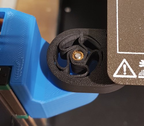
Yeah, the Ruthex and CNC Kitchen inserts are smaller than the Voron standard inserts. That is the right direction to take in Blender. Unfortunately there is no simple way to specify an actual dimension. I will select the feature that I want to modify and temporarily copy it on an orthogonal axis to visually determine what size it currently is (I make all of the heat-set recesses 4.7mm in diameter). Ruthex suggests a 4.0mm hole for their inserts. So you would divide 4.0 by 4.7 to find an accurate ratio which calculates to 0.851. Printed holes usually end up undersized so your 0.9 ratio should be fine. I use Alt+click to select edge loops, or your Ctrl+click method, but I prefer to work in vertex mode (pro tip: 1, 2 and 3 quickly changes between vertex, edge and face select modes). With only those vertices selected you go to Mesh > Snap > Cursor to Selected. Then you need to change your Transform Pivot Point to 3D Cursor (in this situation, Bounding Box would work as well). Then you can select all of the vertices/faces that need to be scaled and use the Shift+Z option. In my working file I do not triangulate the faces so I am able to use Alt+click in face select mode to quickly select the whole ring of faces. If you select everything, then under the delete menu you can select Limited Dissolve with a Max Angle of 0.1 to make the mesh easier to work with but not loose any geometry. When you export the .stl, Blender will triangulate all of the faces again.1 point
-
That's great, thanks. I printed this out but found that the heatset inserts don't match what I have are a bit too small. I've downloaded Blender to try and sort this out - is it correct to use edit mode -> edge select -> hold down ctrl to pick shortest path around the circle -> press s -> press shift+z to lock z -> type in the ratio (I used 0.9)? Is there a way to change the diameter specifically rather than as a ratio? Thanks1 point
-
I've printed the new cores today, will test it out Edit - Could you provide me with the coordinate of the four holes on the back of the new core please? I tried converting it to a part in FreeCAD but I can't seem to get good coordinates of the holes as the mesh cannot be easily simplified by the program.1 point
-
Cool stuff! One problem is that the ProosaXY runs two belts vertically in the Core XY setup where the Prusa just uses a single horizontal belt for the X axis. This would still be a great start for making a standard Prusa backplate. The other thing that I noticed is that there isn't much room for some hotends. I will see if I can find some time to tinker with this design and hopefully make something that would fit more extruder/hotend combinations. Edit: Stay tuned.. I think I will be making a second set of all the core pieces that will replace the need for the orange spacer above and add a lot of rigidity to the toolhead. This should help with StealthChanger compatibility as well.1 point
-
FYI Someone has made a backplate for the ProosaXY already, and I think it should be fine for the mk3s as well. https://github.com/EiNSTeiN-/ProosaXY/tree/master/STLs/3rd-parties/extruder I screengrabbed the image from the Discord server.1 point
-
I was able to find it. I've attached the file to the original post. That was one of the first models I ever built, so sorry if it's hard to work with, haha.1 point
-
Hi, that's actually perfect. Fusion 360 is my preferred software.1 point
-
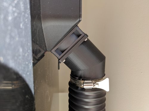
I ended up using a Delta fan, AFB0612EH. I run it at about 45% and there's no ABS fumes whatsoever. My duct is kind of long and has 3 bends in it, once I stop procrastinating and shorten it, I probably will be able to lower the fan speed by 5 or 10%. My chamber temps are around 47-48C with this thing on. Great mod, thank you!1 point
-
Can you share the step files? I want to make some remix to the model. Thanks for great work.1 point
-
oof thats a bit too lose for comfort with how finicky these bltouches are. stress not. ill replace the rail for a big boy rail. thanks for your effort buddy.1 point
-
yeah i know about the side mount. not my cup of tea. dont break your head though. i was only asking. maybe ill just switch out the rail. thx buddy1 point
-
Is it a single MGN9 rail or is the older style double MGN9 setup? If it is a single rail, it might not be too hard for me to modify the MGN12 holes to fit an MGN9 (C or H?) linear carriage. I think the older double MGN9 would require designing a new x-carriage from scratch and I'm a little short on time currently.1 point
-
I forget which fan that was but in truth, you can use any thickness fan you want, as long as you can screw it down. I've found using thicker fans (20 or 25mm) can move more air with less noise, but the devil is in the details (and a heaping portion of personal preference).1 point
-
Sorry, i have been very busy these days. I measure : 24mm581 point
-
Lover over 3000 ! i'll try to print them in these days, i need to find a way to use the original part as i have nothing left ahah thanks again for your amazing work !1 point
-
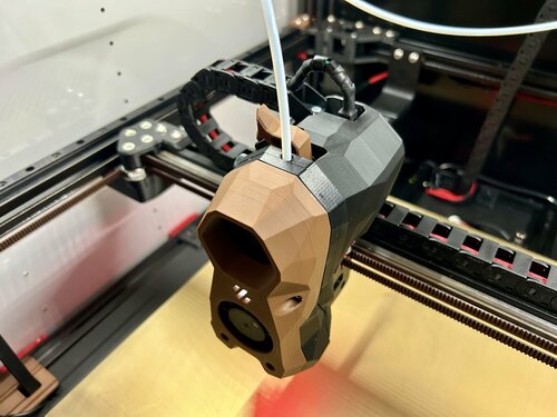
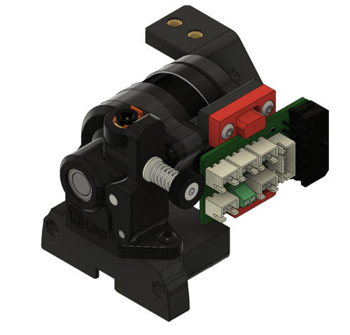
For the EBB36 you will need the Motor Bridge and the PCB mount. The M3 screws go through planetary gear cover and the stepper motor then thread into the motor bridge which fits two M3 heat-inserts for securing the PCB and mount from behind. The hole you can see in the PCB mount is for connecting the cable door with another M3 screw. You can also see the blue reverse-bowden press-fitting that makes it easier to slide the PTFE tube in and out since the shroud gets in the way of accessing the standard Orbiter fitting.1 point
-
As part of a larger update, I have fixed these thin sections on all of the shrouds and pushed the change to GitHub.1 point
-
oh no my dear sir. i was just screwing around here to show the hole. those settings are for a specific part that we use in our machines. i usually dont surpass 4 walls and mostly do 20% infill.1 point
-
For a SW ! thanks a lot my friend ! i'll keep you in touch !1 point
-
Which printer? This core with this cropped Diff IR shroud can fit the BL Touch on the side with this bracket. But on a Trident, V2.4 or Switchwire, you would use a standard cropped shroud with the appropriate MicroProbe x-carriage.1 point
-
ill c if i can rework that to maybe carry the bltouch even though it may push the head forward a bit. thank you for your effort.1 point
-
Well that wasn't too hard. I just don't want to have to make 73 more of these right side versions O.o [a]_MiniStealth_Shroud_Orb2.0_DiffIR_right-side_CropTop.stl1 point
-
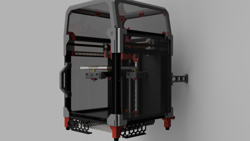
you sir are a gentleman and a scholar. thank you very much. the attached step file is only for those that wish to incorporate it in their drawings for easier constraints when doing the assembly. for the bl touch, i assumed that it mounted there. do you think the shroud would still fit with the orbiter if it was printed mirrored? also for the carriage, from what i have seen of the switchwire style carriages is that the belt mounting is different. i only have a single belt so ill just make my own. however i may convert this to switchwire style in the near future. and you are correct, the gantry has been retrofitted with the same parts as the ender to accommodate a belt driven dual z axis. im very excited about the work you have done here, the dragonburner has too much plastic and parts in my opinion, and maintenance seems way easier on yours. truly a work of art.1 point
-
Sorry about the lack of a .step file. It is all raw mesh-editing in Blender for me.. This BL Touch mount fits onto the Diff IR shroud with a pair of M2.5x6 flathead screws. I looked up the Alfawise U20 and the gantry looks similar enough to the Ender 3 that you might be able to use the MGN9 Switchwire style x-carriage I have recently added to the repo. It stays pretty close to the 2020 extrusion and assumes that the back of the MGN9 rail is mounted 4.5mm from the front of the extrusion. There is more information about these x-carriages in this comment thread but the GitHub files are more current. There is already a core for the Orbiter 2.0 with the Dragon hotend but thanks for the offer!1 point
-
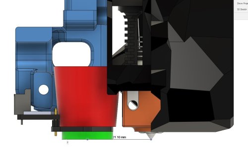
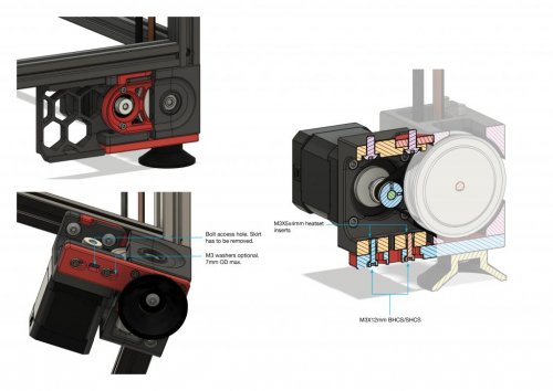
It has been a few months, but I have worked up a new x-frame set for the Ender 3 with a front facing MGN12H linear rail/carriage. This is derived from a Switchwire x-carriage and uses two M3x40 SHCS and nuts to connect the two halves together. There is a toothed wedge that fits in from below and clamps both belt ends in place. It requires four M3x10 BHCS to secure the assembled x-carriage to the MGN12H linear carriage. Two M3x45 BHCS secure the Mini Stealth core to the x-carriage but they require 1.5mm of shim washers on each screw to avoid hitting the MGN12H linear carriage when installing. When installed, the nozzle sits 9.3mm lower than with a stock Ender 3 setup and 20.7mm further forward. EDIT: The original x-frame left/right pieces extended slightly behind the 2020 gantry extrusion and would foul on the plates that hold the V-wheels for Z axis travel. The new pieces should have enough clearance. EDIT 2: This fits on an MGN12H linear carriage and not on the shorter MGN12C as stated before. I am working on applying this design to a front mounted MGN9H linear carriage and then I will design x-carriages for MGN9H and MGN12H top mounted linear rail setups. Belt Clamping Wedge.stl Ender3_MGN12H_Front_x-frame_Left_v1.1.stl Ender3_MGN12H_Front_x-frame_Right_v1.1.stl1 point
-
File names have "6x3", but looks like the model is for 6x2 magnets... also, thought for a second that github is broken for not showing the 6x3 version - and then discovered they are hosted here only. could you add them to github as well? thanks1 point
-
what cooling option do you have with ebb36 fully enclosed because it gets damn hot, my ebb42 gets to around 80° when printing abs in a 55° regulated enclosure and that is an open back and i’ve not installed my sb cw2 ebb36 yet but i know that has heat issues too…1 point
-
Thank you so much. I'll definitely try it out if an ERCF compatible version gets made.1 point
-
the edited skirts have no holes for power inlet etc if you are doing R21 point