Leaderboard


Popular Content
Showing content with the highest reputation since 06/16/2024 in all areas
-
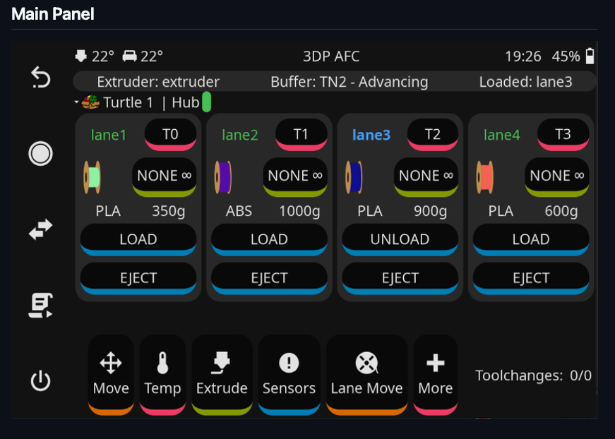
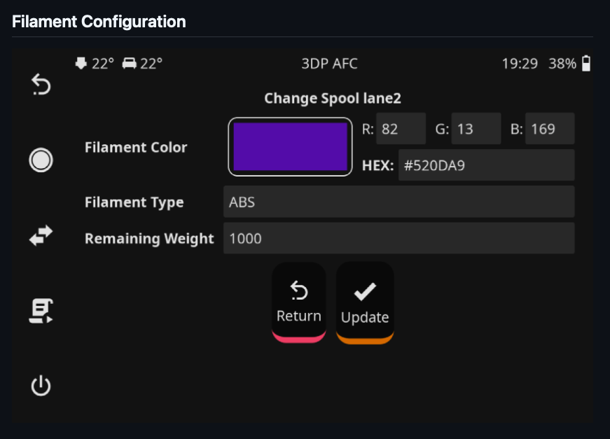
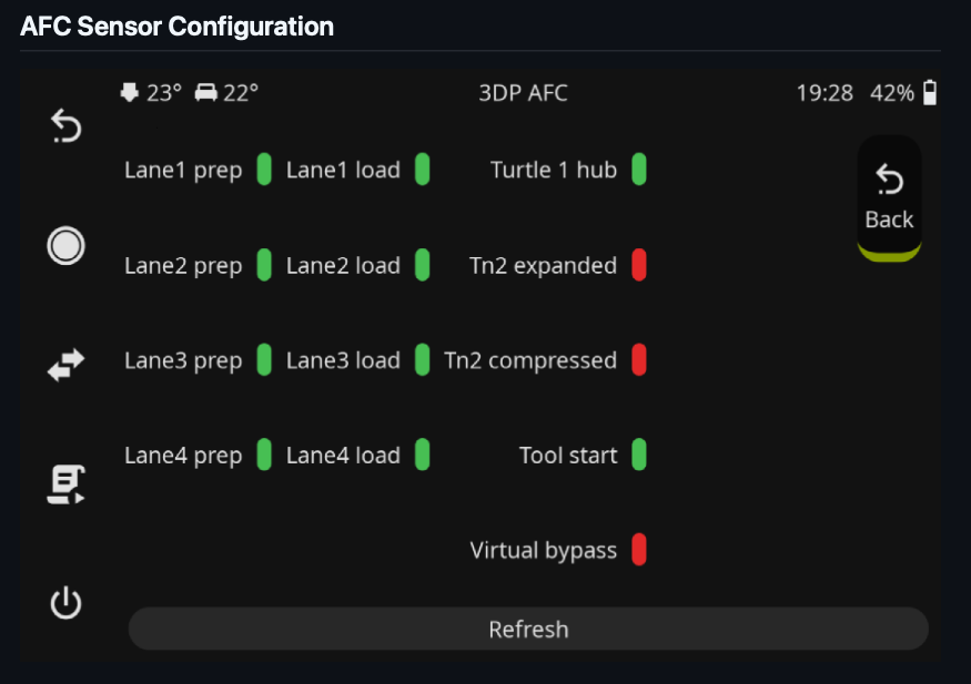
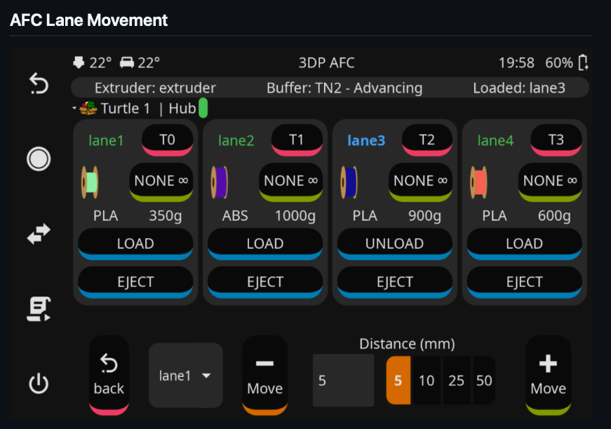
For those interested - a KlipperScreen add on for the Box Turtle running AFC software. Github repository:
 7 points
 -
As the title states, I picked up a Milo V1.5 110v US Kit from Hector at Fabreeko last week while I was in Fort Lauderdale during the holidays. Here we are getting scorched by the afternoon sun, Milo is in the trunk with Steve Builds old Subaru that Hector bought from him in the background. Awesome guy, he gave me a full tour of his very impressive shop and warehouse. A number of things he sells he makes himself on a HAAS H2 mill and laser. I have to finish up my Voron 2.4 refurb first then I start on the Milo. Of course, there will be a build diary so stay tuned. I'm going to build a bone stock Milo at this point (famous last words, I know) if I do anything it will most likely be chip/swarf management related. I'll be printing parts in anticipation of the build. When I get those going I'll start a diary. Cheers everyone, Hope you had an awesome holiday! Pete aka Penatr8tor
7 points
-
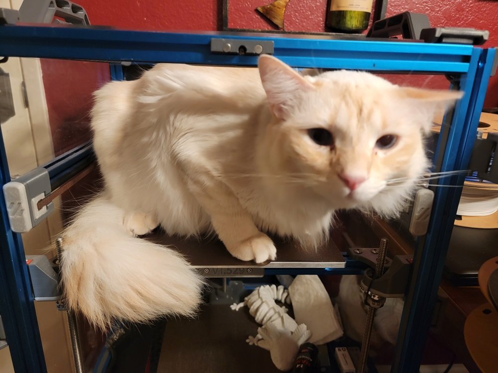
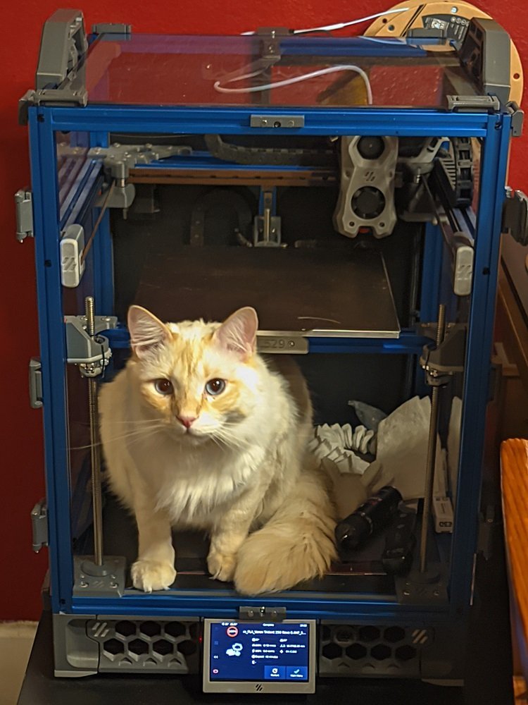
Hey all, I just installed an active chamber heater in the Trident! Also doubles as a bed heater (active--thus the motion blur). For whatever reason he's become fascinated with the printer lately. Now I really have to keep on top of cleaning the purge lines & skirts; can't have him eating them. Also have to keep the top panel on even for PLA because, yes, the dumbshit tried climbing in while it was running.
7 points
-
This is quite misguided. I am a director of BTT and oversee the design process. I can assure you that BTT makes every effort to investigate issues, solve them and then iteratively improve on designs. A perfect case study is the thermistor circuit in question. Some on this thread have asked why it is designed the way that it is and our answer to that is simply this: try to kill our MCU by shorting 24V to the thermistor input (more common than you think when people clean with a wire brush and the hotend is active). You simply can't because the MCU is well protected by a high input impedance and any additional power is shunted to the power rails. This will not be the case on some other manufacturers with different circuits. We don't have a 100k resistor not because we want to save the absolutely, completely, thoroughly insignificant amount of money that a resistor costs to place but rather because we used to ground these holes and that caused ground loops. We never considered that a slow discharge would help with ESD events but now that is something that we are going to take into consideration and use to iteratively improve. Additionally, we will also be adding some ESD absorption circuitry to the thermistor input to save the thermistor in case of an ESD event.7 points
-
Version 1.0.0
643 downloads
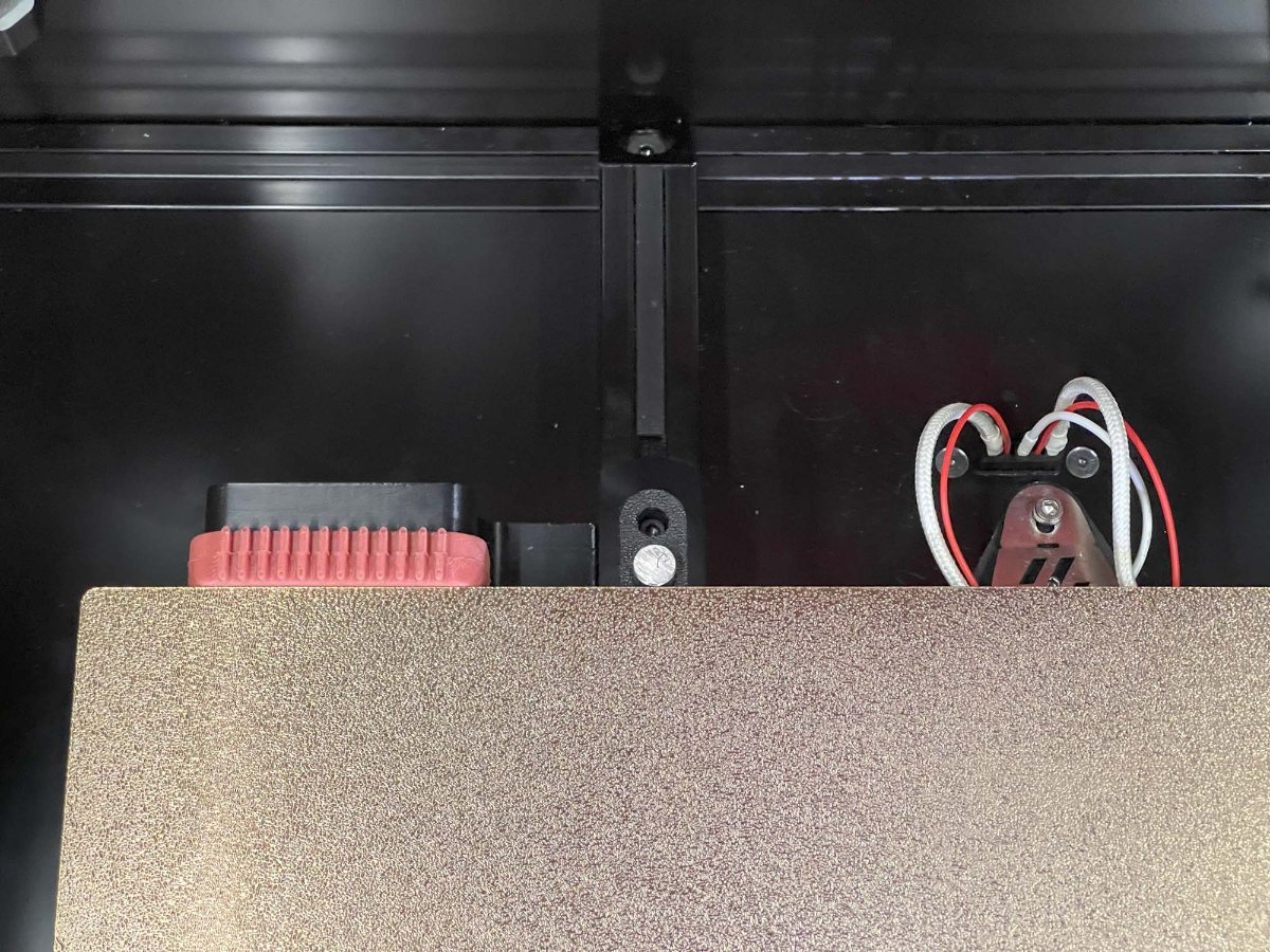
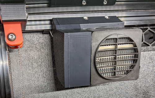
I was having trouble getting my enclosure temperatures above 45C to achieve my optimum print settings. This is the solution I came up with to solve my enclosure temperature issues. I'm running a Fystec Spider v1.1, so your printer config would likely differ. I'm also using a Hartk v4.0 PCB that has an integrated chamber thermistor. I've included my settings for this as well, but you may need to change this up if you use a different thermistor for enclosure temperature readings. I hope this is helpful for someone. I couldn't find a lot of solutions out on the net that could get me up and going with a setup like this, so it was a lot of trial and error to get to this point. Let me know if you have any comments or suggestions that can help me make this thing better! How I set things up: I removed the fan from the PTC heater and inserted a 100K NTC thermistor into one of the bordering fins on the heater core. I then filled the remaining gap in the fin with thermal grease and reattached the fan. I added a thermal fuse to make sure the power would get cut if the temperatures get out of hand from a bad config or faulty piece of hardware. First I drilled a 1/8" hole next to the center ground pin, rivetted the fuse to the heater's core, and applied thermal grease between the fuse body and the heater core. I then moved the ground wire to run from the fuse rather than the tab. Once I wired this up, I ran the temperatures up past the fuse limits to verify things fail safely as expected. I then replaced the fuse after test failed as expected. I extended all of the wiring with solder connections to make sure it would be long enough reach each wire's intended destination, and capped each connection with heat shrink. I mounted the PTC heater to the printed PTC heater mount and ran the wires to the wiring compartment. I installed the Omron relay, and ran a 24v output from my controller to the relay's 5-24v input. I then routed 110v AC to the other end of the relay on the hot lead. I finished up the wiring by hooking up the 12v line for the heater fan and the heater thermistor to the controller board. (Note: my chamber thermistor was already installed on my toolhead's PCB) I updated my printer.cfg and ran a bunch of tests on the heater to make sure it was functioning properly. BOM: Electronics: - PTC Heater w/ Fan x1 - Item on Amazon - NTC 100k thermistor - Item on Amazon - 120C Thermal Fuse - Item on Amazon - Omron 5-24v Relay - Item on West3D Printed Parts: - Printed PTC Heater Mount x1 Miscellaneous: - M3x8mm SHCS x2 - M3 T-nut x2 - 18awg stranded wire ~2 meters - 22awg stranded wire ~2 meters - 1/8" Rivet x1 - Appropriate connectors for you controller board Changes to printer.cfg: ###################### ### Chamber Heater ### ###################### [heater_generic chamber_heater] heater_pin: PC8 sensor_type: Generic 3950 sensor_pin: PC2 control: watermark max_power: .5 min_temp: 0 max_temp: 110 [verify_heater chamber_heater] max_error: 120 check_gain_time: 120 hysteresis: 5 heating_gain: 2 ########################## ### Chamber Heater Fan ### ########################## [heater_fan chamber_heater_fan] pin: PB6 max_power: 1.0 heater: chamber_heater heater_temp: 40.0 # fan will turn off below this level ############################# ### Enclosure Temperature ### ############################# [thermistor chamber_thermistor] temperature1: 25 resistance1: 10000 beta: 3950 [temperature_sensor enclosure_temp] sensor_type: chamber_thermistor sensor_pin: PC1 min_temp: 0 max_temp: 80 Macro: You can run this and immediately start your print. The print wont actually start until the specified chamber temperatures are reached. [gcode_macro CHAMBER_TEMP_WAIT] gcode: {% if params.MIN_TEMPERATURE and params.MAX_TEMPERATURE and params.MIN_TEMPERATURE|float > params.MAX_TEMPERATURE|float %} {action_raise_error("Chamber Temp Wait: MIN_TEMPERATURE must be less than or equal to MAX_TEMPERATURE Use: - CHAMBER_TEMP_WAIT MIN_TEMPERATURE=[0..80] - CHAMBER_TEMP_WAIT MAX_TEMPERATURE=[0..80] - CHAMBER_TEMP_WAIT MIN_TEMPERATURE=[0..80] MAX_TEMPERATURE=[0..80]")} {% elif params.MIN_TEMPERATURE and params.MIN_TEMPERATURE|float > -1 and params.MIN_TEMPERATURE|float < 81 %} {% if params.MAX_TEMPERATURE and params.MAX_TEMPERATURE|float > -1 and params.MAX_TEMPERATURE|float < 81 %} TEMPERATURE_WAIT SENSOR="temperature_sensor enclosure_temp" MINIMUM={params.MIN_TEMPERATURE|float} MAXIMUM={params.MAX_TEMPERATURE|float} {% else %} TEMPERATURE_WAIT SENSOR="temperature_sensor enclosure_temp" MINIMUM={params.MIN_TEMPERATURE|float} {% endif %} {% elif params.MAX_TEMPERATURE and params.MAX_TEMPERATURE|float > -1 and params.MAX_TEMPERATURE|float < 81 %} TEMPERATURE_WAIT SENSOR="temperature_sensor enclosure_temp" MAXIMUM={params.MAX_TEMPERATURE|float} {% else %} {action_raise_error("Chamber Temp Wait: invalid usage Use: - CHAMBER_TEMP_WAIT MIN_TEMPERATURE=[0..80] - CHAMBER_TEMP_WAIT MAX_TEMPERATURE=[0..80] - CHAMBER_TEMP_WAIT MIN_TEMPERATURE=[0..80] MAX_TEMPERATURE=[0..80]")} {% endif %} Updates: - I added a photo of how this is wired up in the wiring compartment. The boxes with the text in the photo represent the components of the heater that are in the chamber of the printer. - I have included the macro to wait for chamber to reach temps before starting a print. - I have attached the heater mount's fusion 360 file for others to be able to easily make edits to the chamber heater mount Chamber Heater Mount v2.f3d6 points -
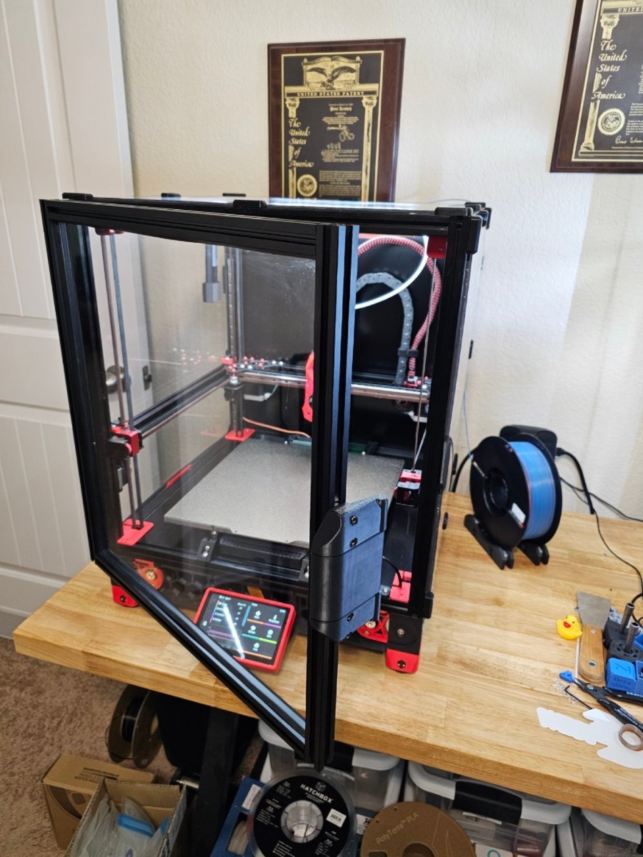
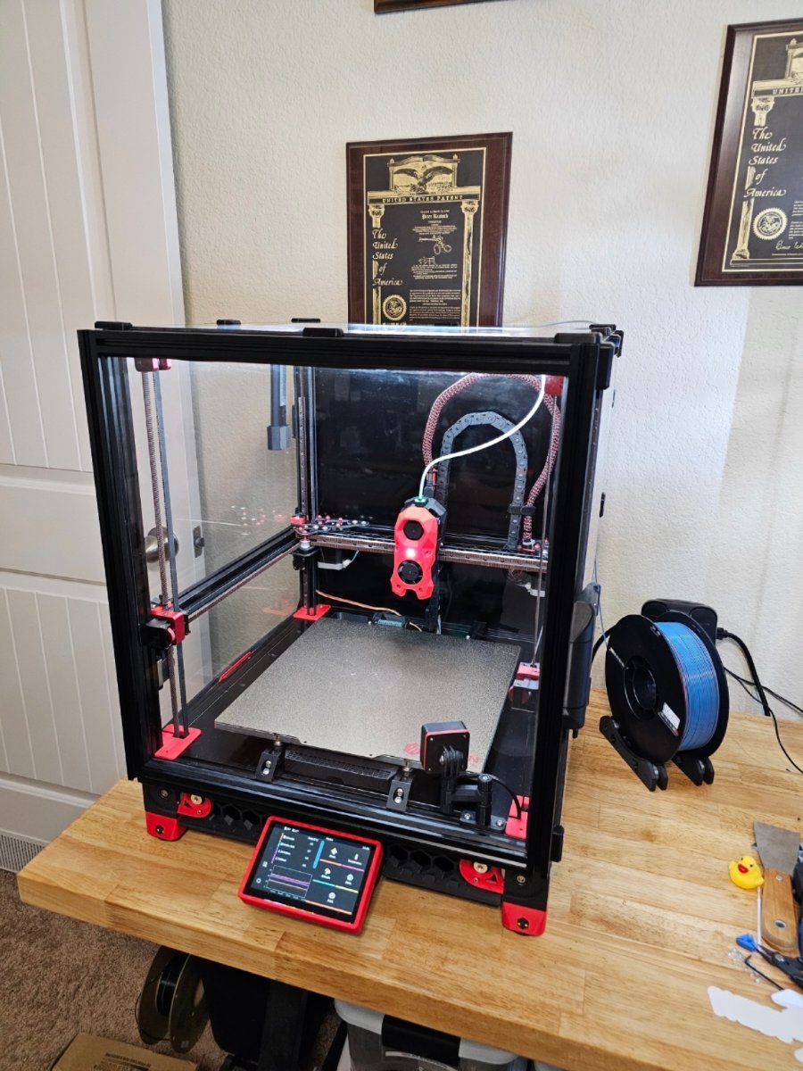
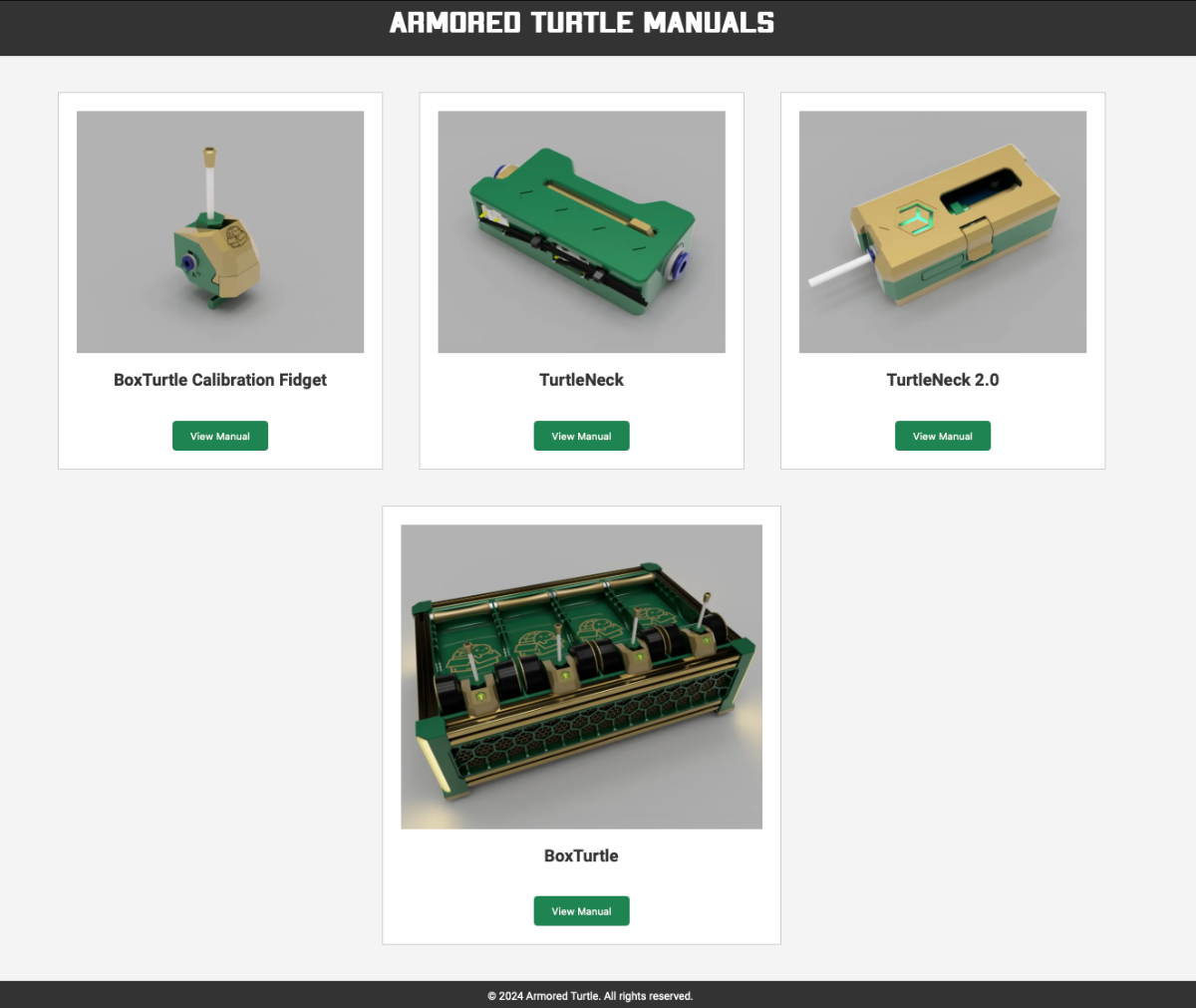
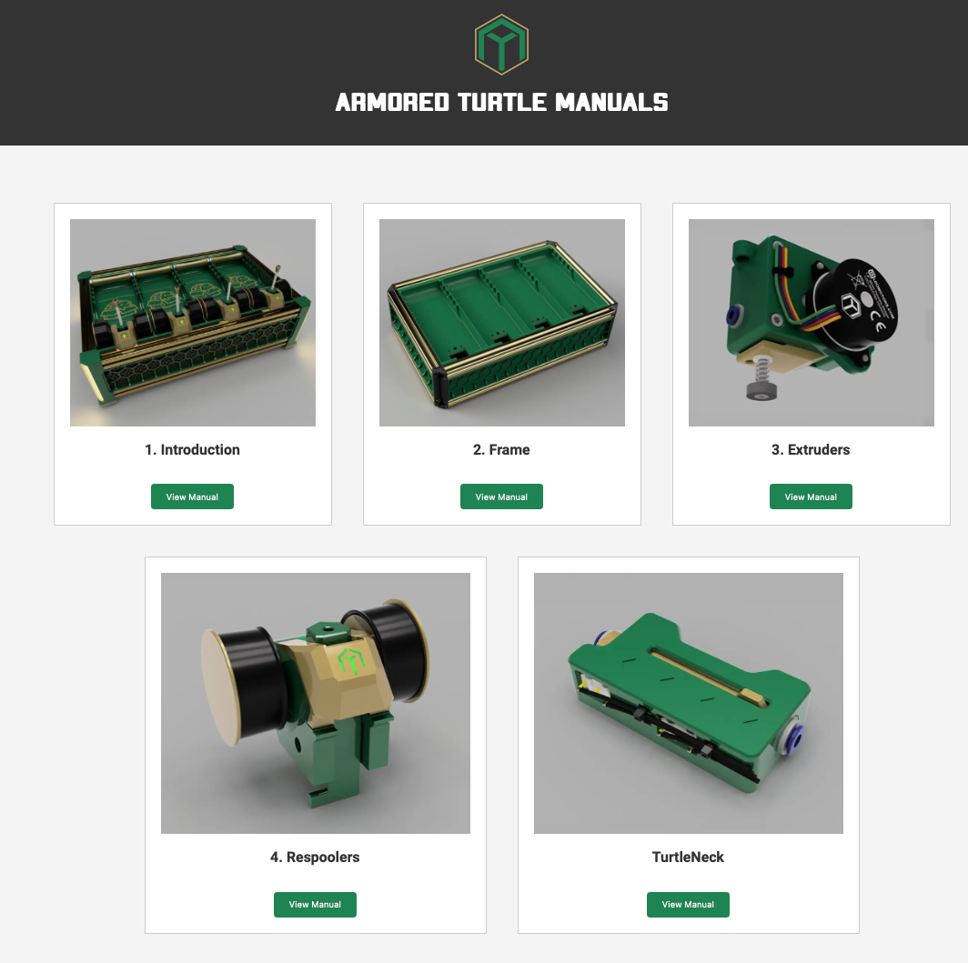
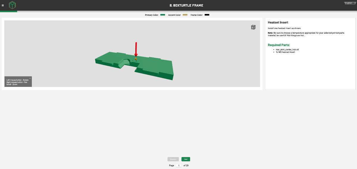
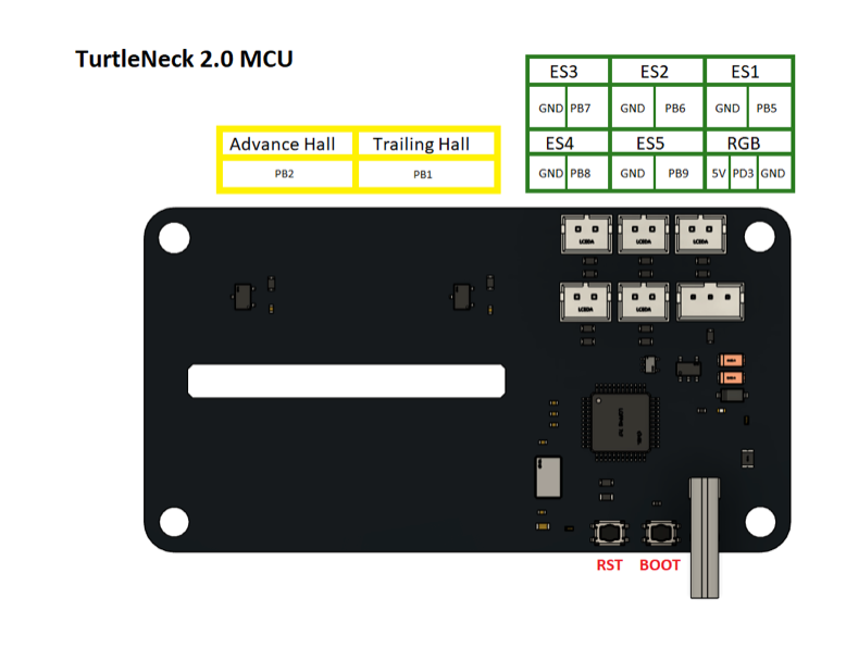
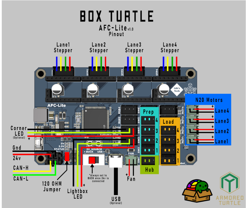
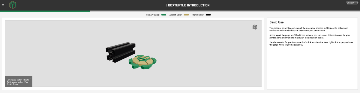
Well, I bit the bullet @7milesup. Here is the build diary of the Box Turtle AMS style Filament changer from Armored turtle. The Preamble: Decided on a Green and Gold (Actually it is yellow) colour scheme - I am in Australia after all! Opened the stl file configurator from the Build manual website, which gathers the stl's you need and packs it in a zip file for downloading. This is one of the things I really like - no sifting through directories of stl's to find what you need to print. Answer a few questions and away you go. I also like the way the build manual is compiled. (as is my habit, I read through the manual before starting the project). Though it is web based, and not in downloadable pdf form, it works. Instructions are clear and most of all, they are accompanied by a 3d-rotatable picture of the step you are at - Love it! No more twisting of necks to see exactly what needs to be done - just rotate the image. In addition to the Box Turtle stl's, you'll need to decide on an extruder sync sensor (Toolhead Buffer). I chose the Turtleneck buffer system as I have the Belay sensor on the Tradrack and wanted to build something different. The turtleneck has been advanced to the turtleneck 2, but that requires a dedicated PCB (Turtleneck2 MCU). (I may just order that - see how it goes). This can be ordered from Isik's Tech Site, as well as the dedicated ACF board. In addition to the toolhead buffers, a filament sensor is needed in the toolhead. I choose the integrated one's for the stealth burner from the ERCF project, as all the printers already have these toolhead installed. The other option is the Armoredturtle Filatector in-line sensor. (So spoiled for choice) The Build: 1. Box Turtle introduction. The introduction goes through the print settings, explanation of instructions, assembly queues and links to the stl-generator, GitHub and discord. It also discusses part selection and this is handy when it comes to using the stl-generator. I would suggest printing the "Calibration Fidget" in order to determine your printer tolerances, especially if you will be using two seperate printers to print the parts. (I generally load the bigger of the printers with the main colour parts and another smaller printer with the accent colour parts). The printers used on this build was the VZBot 330 for the main coloured parts, The Trident 300, for the accents and the V0.2 for the clear, opaque and TPU parts. Next: 2. Boxturtle Frame
6 points
-
Nothing really changing on this--it's getting occasional use lately. But a fun little anecdote. My daughter needed a prop for a book report project in school. The book was The Boys In The Boat and she wanted a racing shell model as a display. I managed to find one on Printables; a single-seat modern one, but it gets the idea across. I made sure to use the V0 that she built and told her to mention that fact. The report went well (she got an A. ) and she said the teacher mentioned that was the first time anyone used a 3d printed prop. She later told me she also got extra credit after telling the teach that she built the printer used to produce the boat model.6 points
-
Version 1.0.0
87 downloads
This simple mod will give you the ability to add 4010 or 4020 fans to your AB drive motors on your Voron 2.4 Additionally you can use generic 3950 NTC for temperature controlling the fans if you have enough pin on your controller board. I've designed my own controller board and I considered 5 NTCs so I could easily adapt to this mod. Why I made this mod? Personally I like to keep my motors temperature around 55-60°C for this purpose I needed active cooling, Based on tests using a high speed fan at PWM around 50% is enough to keep my motors cool while keeping fan noise to minimum. So at maximum 50% pwm for fans they are silent enough not to hear them and sufficient enough to cool motors properly. What you will need for each motor: 2 M3x5x4 Threaded instert 1 AB Drive Fan for Voron 2.4.step 2 screws are the height of your fan + 5mm extra (for 4010 fans 3x15mm, for 4020 3x25mm. Best use BHCS). 2 screw 5mm longer than your motor screw File are super easy to print and super easy to adapt. You'll need one fan holder per motor and one NTC holder for each NTC. Print with default voron settings and no support. Installation: First put 2 inserts into their designated holes in motor holder in opposite diagonals (bigger holes). Then remove 2 diagonals screws from your motor. Preferably the one that has no screws on top side and it's diagonal one. Measure your motor screws with a ruler or caliper and use 5mm longer screws to attach motor holder to your motor. Now you can use 2 screws 5mm longer than your fan height to attach your fan to motor fan holder using insert you added earlier Optionally you use ziptie and heatsink compound to attach a NTC to the body of your motor for temperature control. 200x3mm ziptie must be sufficient for this purpose. "AB Motor Thermistors Holder.stl" are for holding thermistor in place. Here is the klipper config for controlling each fan separately based on their temperature: #-----A MOTOR FAN---# [temperature_fan motor_a] pin: PB10 sensor_type: Generic 3950 sensor_pin: PC3 kick_start_time: 0.5 off_below: 0.1 max_power: 0.5 min_speed: 0 shutdown_speed: 0 min_temp: 0 max_temp: 150 target_temp: 55 control: pid pid_kp: 1.0 pid_ki: 0.5 pid_kd: 2.0 #-----B MOTOR FAN---# [temperature_fan motor_b] pin: PB12 sensor_type: Generic 3950 sensor_pin: PC1 kick_start_time: 0.5 off_below: 0.1 max_power: 0.5 min_speed: 0 shutdown_speed: 0 min_temp: 0 max_temp: 150 target_temp: 55 control: pid pid_kp: 1.0 pid_ki: 0.5 pid_kd: 2.0 Don't forget to change Fan and NTC pins based on your own board. If you want to use simple control without ntcs use this code instead: [output_pin ab_fan] pin: PB1 pwm:true shutdown_value: 0 value:1.0 cycle_time: 0.01 kick_start_time: 0.5 Don't forget to change Fan pins based on your board. Additionally if you want you can use only one ntc for one motor and control both fans based on NTC: #-----AB MOTOR FAN---# [temperature_fan ab_motors] pin: PB10 sensor_type: Generic 3950 sensor_pin: PC3 kick_start_time: 0.5 off_below: 0.1 max_power: 0.5 min_speed: 0 shutdown_speed: 0 min_temp: 0 max_temp: 150 target_temp: 55 control: pid pid_kp: 1.0 pid_ki: 0.5 pid_kd: 2.0 Don't forget to change Fan and NTC pins based on your own board. if you are using Feel free to express your opinion about this mod, edit it or use it however you want6 points -
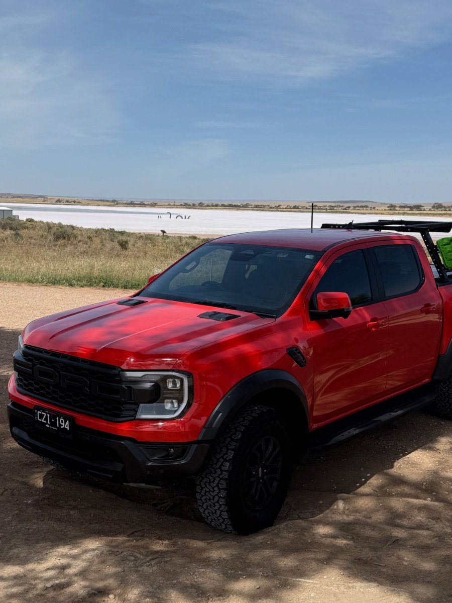
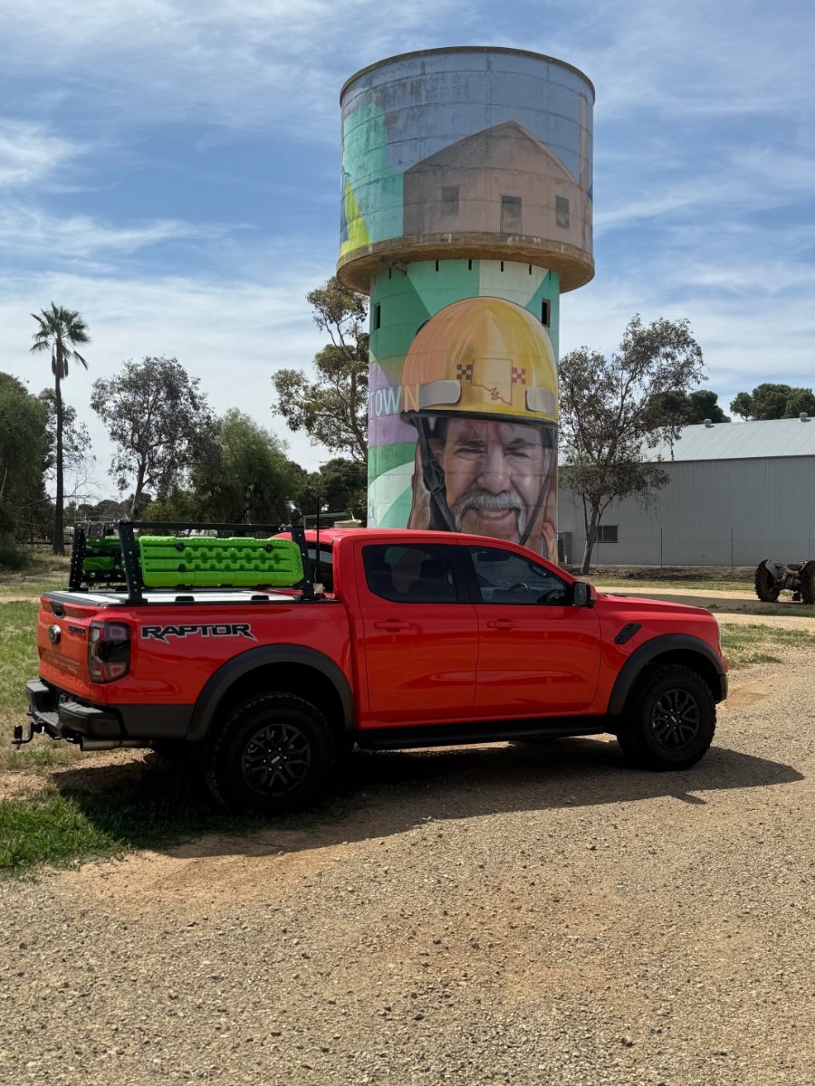
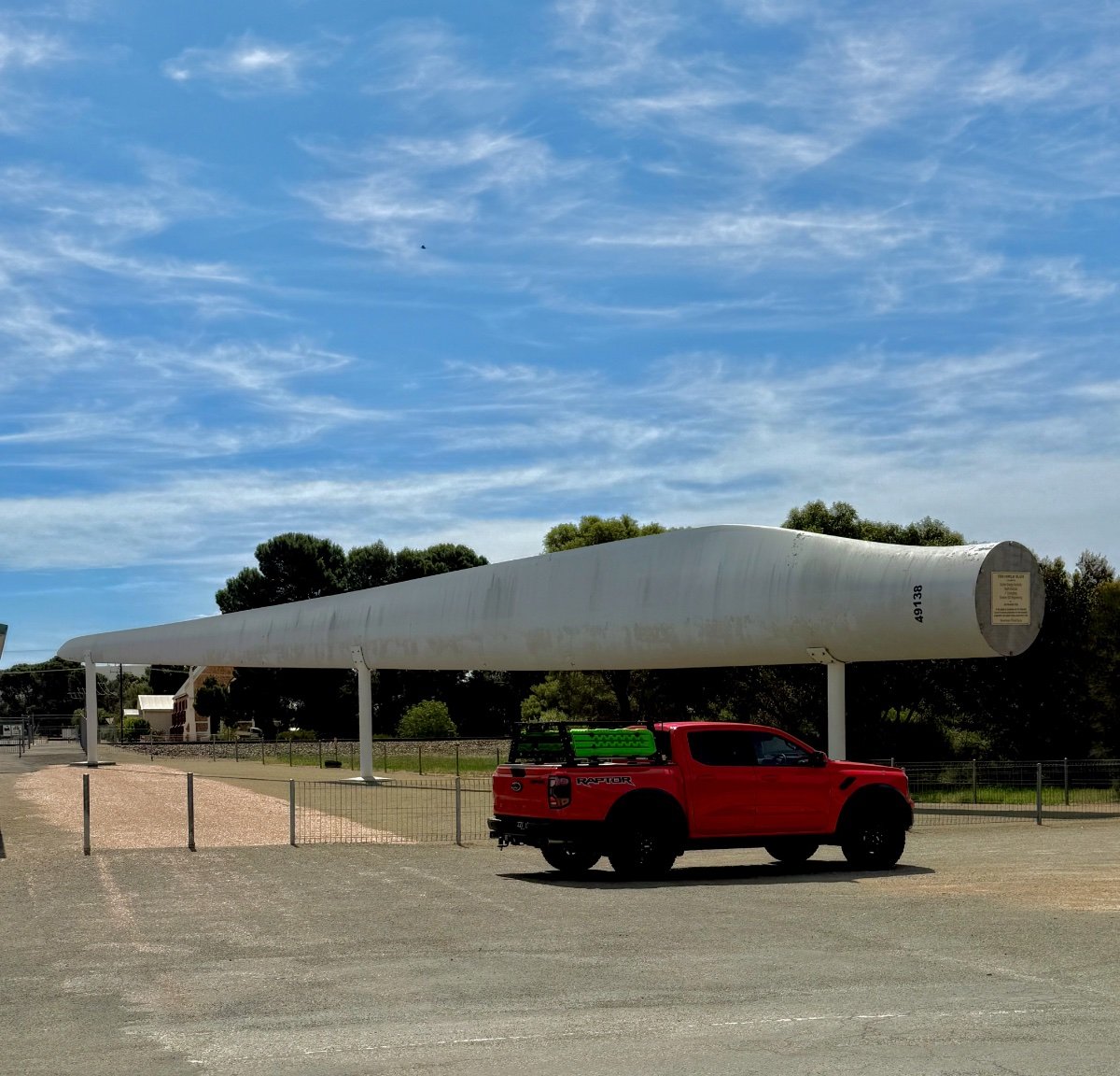
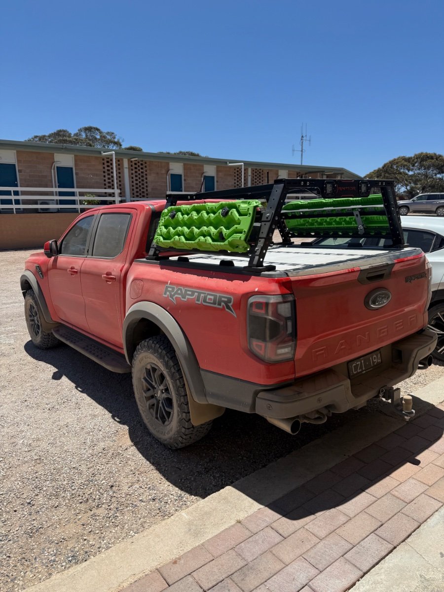
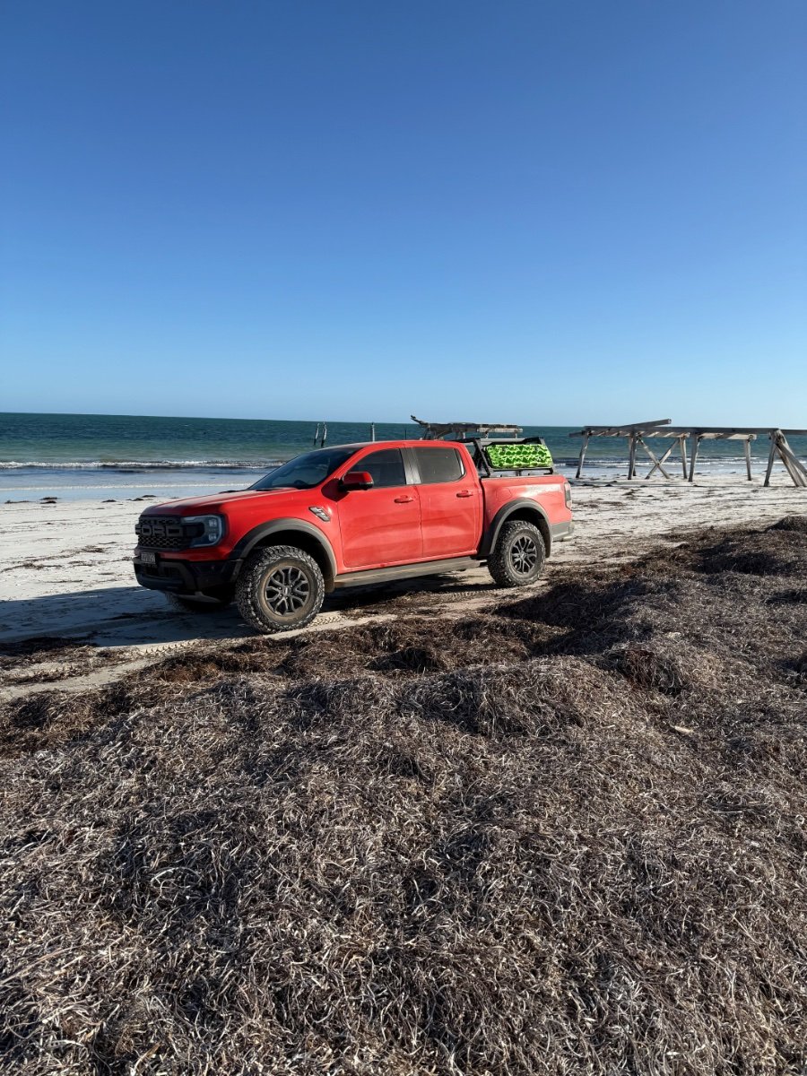
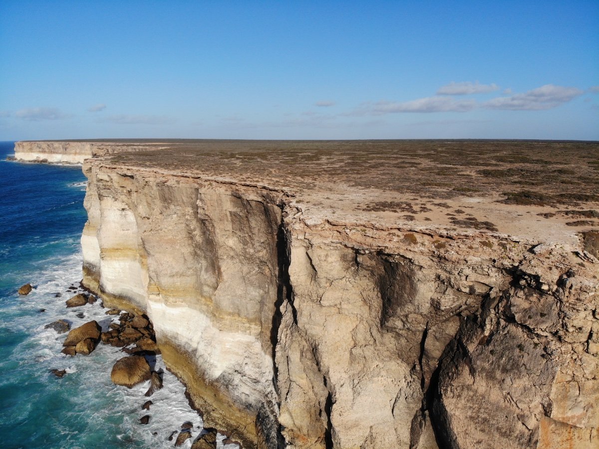
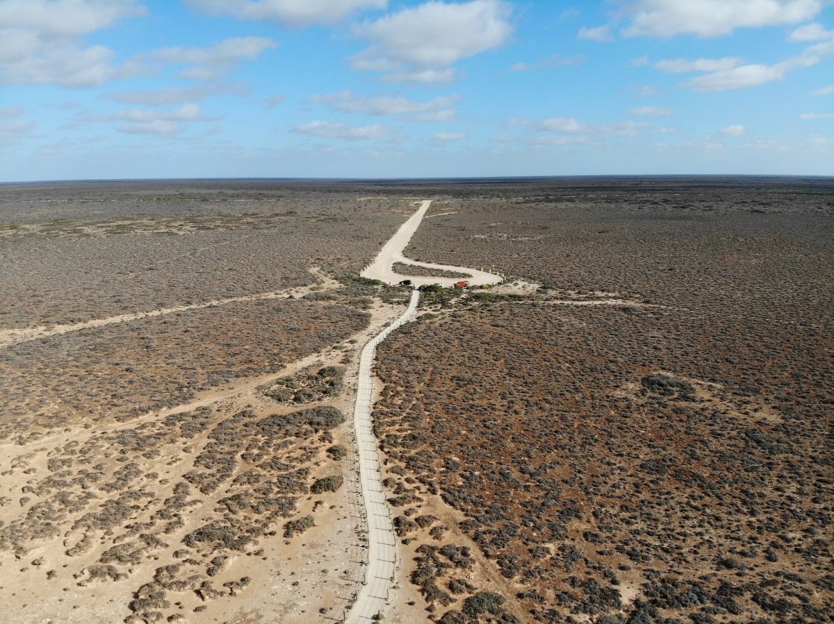
TRIP: Thought I'd share a few photos of our trip across the Nullabour Plain. (Treeless plain) Everyone living in Australia should do this. Had an amazing time and the sights were incredible. Did a total of 7252kmm (4776 miles) in 17 days - and I will do it again. The Raptor performed exceptionally well. Lots to beach driving as well as some off road trials. Unfortunately back to reality now! It sucks! PRINTERS: Better get back to the printers to restore my sanity. Have upgraded all the cartographers (Trident 250, Trident 300 Voron 2.4 300 and Voron 2.4 350) to touch and must say I am impressed. Used the Siboor guide and upgraded all 4 machines without issues. Still intending in upgrading to the Beacon H eventually (I have 4 of them in a tub waiting to be used). Frames are build for the clicky clack (Fridge doors) doors for the above 4 printers. First time I ordered from Misumi - Japan - and boy am I impressed. Quality and packaging - just wow!!. Awaiting the panels from the local supplier and currently printing the hinges, etc. All printers have been serviced Also need to bring the V2.4 300 in to update the motor mounts and idlers with the aluminium parts that has been sitting around for the past 6 months or so! Sigh........... Also need to decide what to do with the two ender 5's in storage. (a 5 and 5 Plus). Both are heavily modified already with linear rails and stealth burner toolheads. Was going to buy a Ratrig VCore 4 for something to do, but at nearly $5000AUD, I just cannot justify it, no matter how much I love this hobby. So do something with the enders! @7milesup - I have bitten the bullet and self sourced the parts for the Armored turtle - BoxTurtle. Have ordered the custom PCB and this has just shipped. Will do a build diary once all the parts are received. Kits are on backorder here in Oz (shipping in January 2025) and sell for around $500AUD. Sourced all the parts including the custom PCB for around $220AUD (including shipping) and should have all parts here in a couple of weeks. So for multicolour printing: Voron 2.4 350 - ERCF V2 Trident 300 - Tradrack Voron 2.4 300 - Tradrack Trident 250 - Intend to use armored turtle Til next time!
6 points
-
Version 1.0.0
82 downloads
Attention all Voron users, who among you can attest to desiring a quieter fan for their controller cooling system? Search no more, as we have the perfect solution implemented across all our Voron printers. It maintains the necessary airflow while significantly reducing the noise generated by the fans. This is a crucial addition for those who operate their printers in workspaces. If you like the work I do here at 3D Magic feel free to have a look at some of my other designs : https://cults3d.com/en/users/ThreeDMagic/3d-models Print settings: Material ABS Layer Hight 0.2 or less Parimeters 3 Infill 20% (lines)6 points -
Hey, i hope you're all doing well out there. Just wanted to say thank you guys. Many of you had suggestions and tips that really helped me out. Especially @Dirk @mvdveer @claudermilk. Took me some dang time, but i got it about where i wanted it and its awsome. Just got my serial request in, so i deem it "finished", as far as an ongoing project can ever be. I'll have an iced beverage on you guys.6 points
-
Did you guys hear that FedEx and UPS are merging? The new company will be called FedUp, although they also considered EffdUp.6 points
-
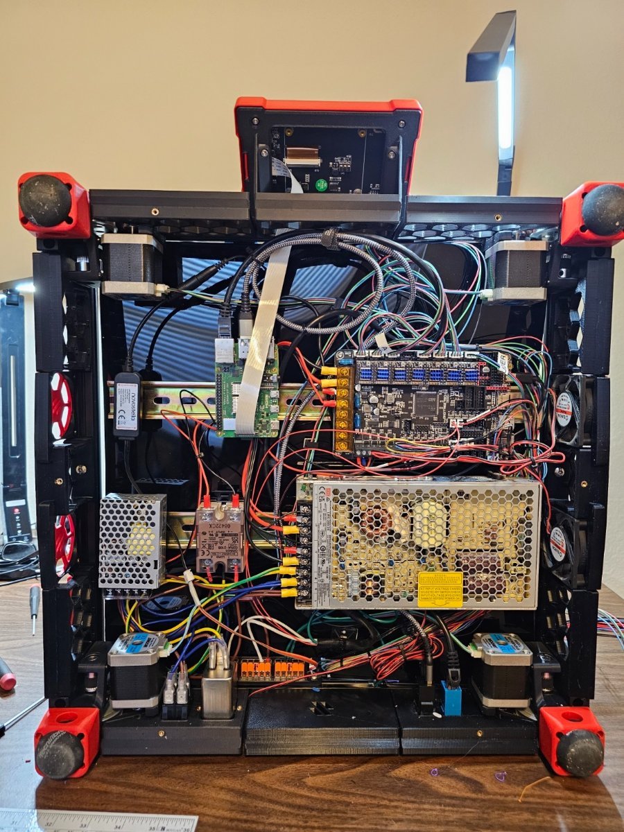
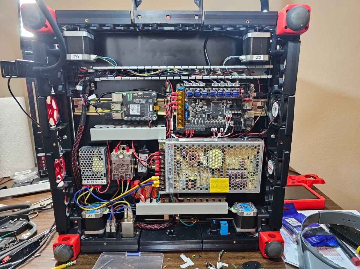
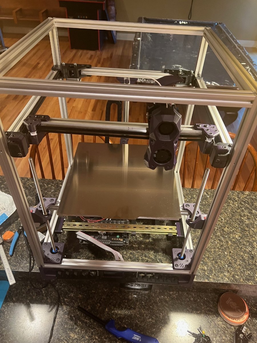
I've been working on the electronics bay. This is the #2 reason why I decided to do a refurb, 1st being the warped deck plate. It was my first printer kit and I just bundled and stuffed the supplied wiring as best as I could. Before... ...and what I have currently. Last night I focused on getting all of the toolhead wiring completed. Only things I have left to do is the TAP/Probe wire, LED wires, X end stop, exhaust fan and a couple things here and there. I'm hoping to power her up this afternoon.
6 points
-
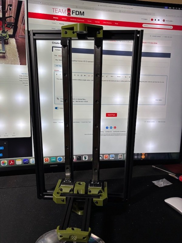
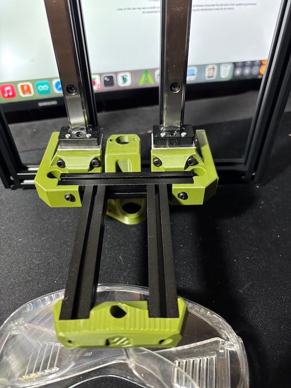
The color scheme for this build is military jungle camo. I opted to source the parts for this build and also to utilize parts I have available including the parts I did not use from the V2.4 kit. I used 2020 for the frame to accommodate the 15mm THK rail and standard 1515 for the build plate mount and the X gantry. As I learned from the first build (Mods as I go), I am now just printing parts as I need them so I can make modifications as needed or desired. This V0 frame is 470mm tall without the hat and 270mm wide. TR8x8 lead screw and coupling to the motor. The weight of the Z with the HSR15 bearings really makes it heavy but at the same time makes me even more curious if it would work Hmmm... I have some new Nema 17 motors on hand (StepperOnline 45Ncm 12-24V) so I will try them first and see. My question is what board can I use that can accommodate 3A (for LDO 42STH48-2504AH just in case) but small enough to fit the V0. Thanks in advance for your inputs.
5 points
-
Version 1.0.0
62 downloads
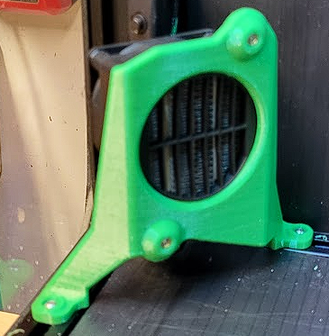
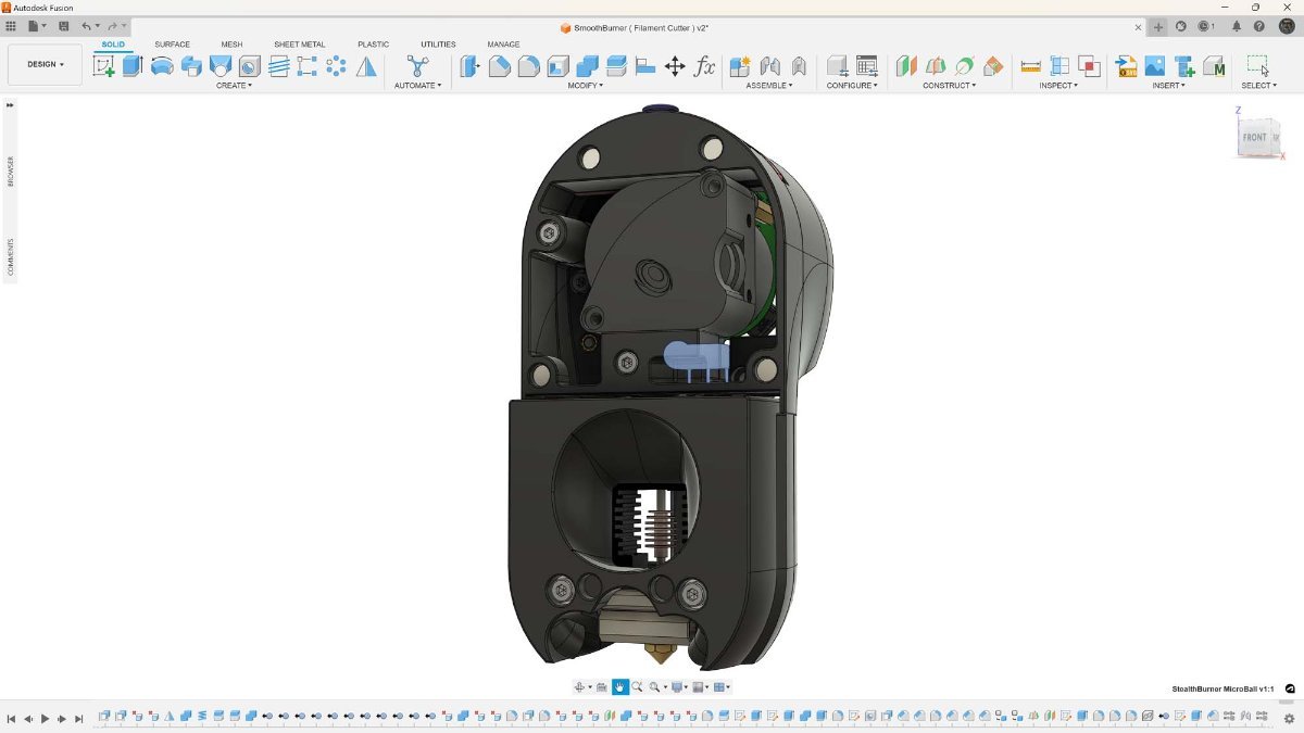
I wanted to reach ABS/ASA temperatures faster, and be able to maintain 55-60°C for those larger warp-prone prints, so I designed this chamber heater mount. If you're going to attempt this, make sure to use a temperature fuse to protect your printer (and your house) from burning down in the event of failure/over-heating. I used 2x 3mmx5mm long heatserts inserted from the front, and 3mmx12mm screws to attach the heater. 4x 3mm t-nuts and 4x 3mmx10mm screws are required for mounting the bracket. I used this 120VAC 250W heater (with 12VDC fan): https://www.amazon.ca/dp/B07NYX5DKD?psc=1&ref=ppx_yo2ov_dt_b_product_details I used this SSR: https://www.amazon.ca/dp/B06WLNHPWK?psc=1&ref=ppx_yo2ov_dt_b_product_details I loosely followed the chamber heater post from @ahough, and this would've been way harder (nigh impossible) without their post and the comments section. Notable mention goes out to @Dousi as well, since I copied and modified their config example to use as my own. I hope the configs below help someone else along their way. ******** ******** Here is my chamber heater section within my printer.cfg file: ******** ##################################################################### # CHAMBER HEATER ##################################################################### [thermistor chamber_thermistor] #define "chamber_thermistor" characteristics temperature1: 25 resistance1: 100000 beta: 3950 [thermistor heater_thermistor] #define "heater_thermistor" characteristics temperature1: 0.0 resistance1: 32116.0 temperature2: 40.0 resistance2: 5309.0 temperature3: 80.0 resistance3: 1228.0 [temperature_sensor heater_temp] #this is the temp sensor for the 10K probe inserted in the heater core sensor_type: heater_thermistor #use temp sensor characteristics as defined in "heater_thermistor" sensor_pin: PA2 #Manta 8P temp sensor input pin. This temp probe is glued to the heater core with UV resin min_temp: -100 #set minimum temp before error/shutdown max_temp: 140 #SAFETY max heater core temperature, printer will shutdown above this temp [heater_generic chamber_heater] #setup chamber heater heater_pin: PE3 #Manta 8P heater output pin to SSR. This temp probe is mounted near the top of my chamber sensor_type: chamber_thermistor #use temp sensor characteristics as defined in "chamber_thermistor" sensor_pin: PA1 #Manta *P temp sensor input pin control: watermark #use watermark control method (on/off) max_delta: 0.1 #set the delta temp to energize/deenergize chamber heater max_power: 1.0 #set maximum power of heater 1.0 = 100% min_temp: -100 #set minimum temp before error/shutdown max_temp: 70 #SAFETY max chamber temperature, printer will shutdown above this temp pwm_cycle_time: 0.01666 #Set this to avoid room lights flickering on higher power heaters. This value works well for 60Hz power. 0.1 is 10Hz [verify_heater chamber_heater] #setup chamber heater verification parameters max_error: 120 check_gain_time: 240 hysteresis: 5 heating_gain: 1 [heater_fan heater_fan] #setup fan attached to back of chamber heater pin: PE4 #Manta 8P fan output pin. Jumper selected for 12V max_power: 1.0 #set maximum power of fan 1.0 = 100% heater: chamber_heater #when "chamber_heater" is ON fan will be ON heater_temp: 30 #fan will turn off below this level ##################################################################### # MACROS ##################################################################### [gcode_macro M191] gcode: {% set S = params.S | default(0) | float %} SET_HEATER_TEMPERATURE HEATER=chamber_heater TARGET={S} M118 Chamber heating to {S}C M118 Waiting for chamber heating... TEMPERATURE_WAIT SENSOR="heater_generic chamber_heater" MINIMUM={S} M118 Chamber heating {S}C is done. ******** ******** I also run Ellis' bedfans, and modified bedfans.cfg, "Command overrides" section to the below: ******** ############ Command overrides ############ # Override, set fan speeds to low and start monitoring loop. [gcode_macro SET_HEATER_TEMPERATURE] rename_existing: _SET_HEATER_TEMPERATURE gcode: # Parameters {% set HEATER = params.HEATER|default("None") %} {% set TARGET = params.TARGET|default(0)|int %} # Vars {% set THRESHOLD = printer["gcode_macro _BEDFANVARS"].threshold|int %} {% if HEATER|lower == "extruder" %} M104 S{TARGET} {% elif HEATER|lower == "heater_bed" %} M99140 S{TARGET} {% elif HEATER|lower == "chamber_heater" %} _SET_HEATER_TEMPERATURE HEATER=chamber_heater TARGET={TARGET} {% else %} {action_respond_info("Heater %s not supported" % HEATER)} {% endif %} # Set fans to low if heater_bed temp is requested above threshold temp, and kick off monitoring loop. {% if HEATER|lower == "heater_bed" %} {% if TARGET >= THRESHOLD %} BEDFANSSLOW UPDATE_DELAYED_GCODE ID=bedfanloop DURATION=1 {% else %} BEDFANSOFF UPDATE_DELAYED_GCODE ID=bedfanloop DURATION=0 # Cancel bed fan loop if it's running {% endif %} {% endif %} ******** ******** II then modified my PRINT_START macro to include the chamber heater stuff as seen below: ******** [gcode_macro PRINT_START] # Use PRINT_START for the slicer starting script - PLEASE CUSTOMISE THE SCRIPT gcode: EXCLUDE_OBJECT_DEFINE BED_MESH_PROFILE load=default # Load variables {% set bed_temp = params.BED|default(60)|int %} {% set extruder_temp = params.EXTRUDER|default(230)|int %} {% set CHAMBER_TEMP = params.CHAMBER|default(20)|float %} M104 S150 #start nozzle heating, keep below oozing temp M117 Extruder Heating... M140 S{bed_temp} #set bed temp to "bed_temp" and move on M117 Bed Heating.... M190 S{bed_temp} #allow bed to get up to temperature M117 Heating Chamber... M191 S{CHAMBER_TEMP} G90 #Use absolute coordinates M117 Homing... G28 M117 Adjusting Z Tilt... Z_TILT_ADJUST G28 M117 Calibrating Bed Mesh... BED_MESH_CALIBRATE M117 Waiting for Extruder to Reach Printing Temperature... M109 S{extruder_temp} G92 E0 #Reset exruder M117 Purging Filament... ADAPTIVE_PURGE M117 ******** ******** I use CURA and this is my Start Gcode as defined within Cura: ******** ;Nozzle diameter = {machine_nozzle_size} ;Filament type = {material_type} ;Filament name = {material_name} M204 P500.00 R1000.00 T500.00 ;Setup Print/Retract/Travel acceleration M220 S100 ;Reset Feedrate M221 S100 ;Reset Flowrate M117 PRINT_START EXTRUDER={material_print_temperature_layer_0} BED={material_bed_temperature_layer_0} CHAMBER={build_volume_temperature}5 points -
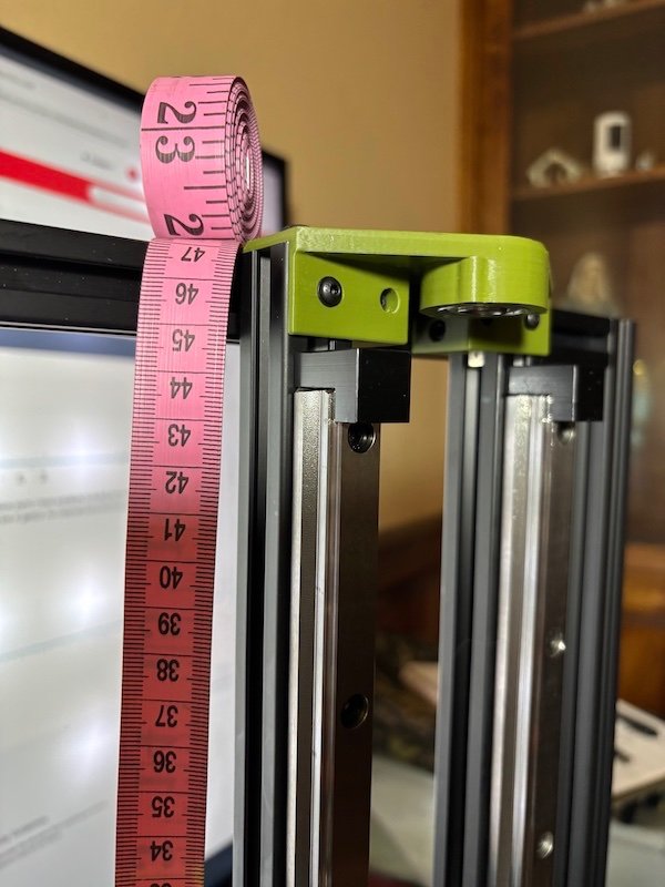
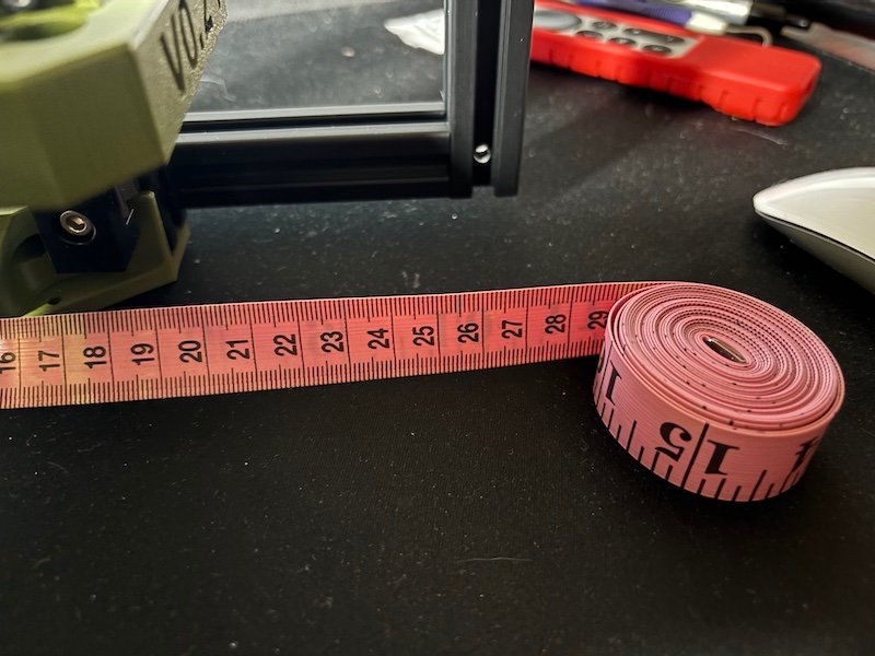
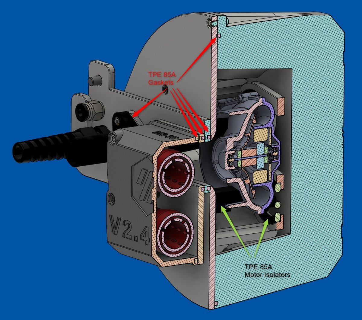
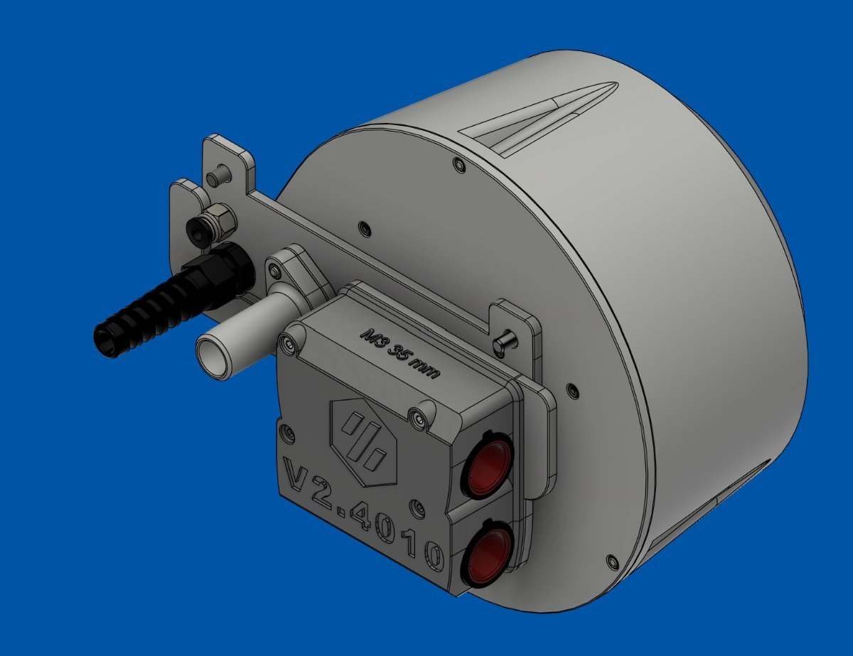
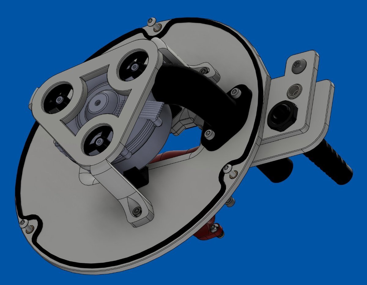
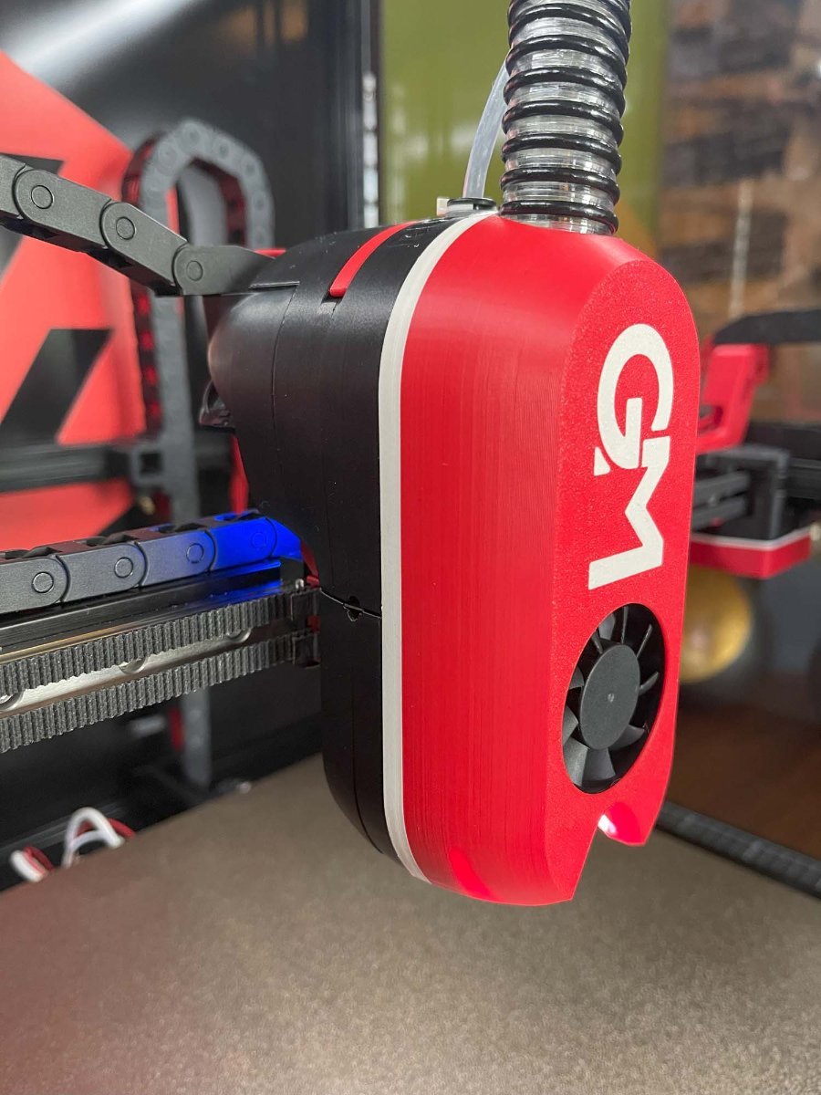
Finally finished the CPAP air supply system and the noise levels, no numbers, just comparing with my other standard Voron Stealthburner, are satisfactory; see below. I need to set up the umbilical "holders" and music wire before starting calibrations and tests. The motor dome may look massive, but it is only 90 mm thick and 165 mm diameter at the widest point. The hatched area it becomes 5% Gyroid Infill that I will assume has excellent acoustic suppression properties. I used TPE 85A to create all the gaskets, and they made a big difference on noise redaction due to air leaks without them. Btw, the air intake muffler is a modified VzBot v2 muffler but using two "tune" pipes in a single housing and added gaskets. The original design was "whistling" from the air leaks! This thing puts out so much more air that I cannot see using more than 40%; we will see soon
5 points
-
This seems like a good place to comment on the new Klipper 0.13 update! https://www.klipper3d.org/Releases.html Klipper 0.13 has some neat new features... but will it crash various MCUs like the Klipper 0.11 > 0.12 did? For me, No, it does not. Victim #1 - Voron 0.2 with RPi4, BTT Pico on USB and BTT EBB36 on CAN via U2C: Went from an earlier version of Klipper 0.12 to 0.13.0.51 with no issues and remained operable with the Pico and the EBB36 still running 0.12 firmware. The Katapult-equipped EBB36 successfully flashed to 0.13 after doing a make menuconfig and reflash. The Pico reflashed by USB without issue. Victim #2 - Voron 2.4 with RPi4, BTT Octopus1.1 on USB and a Mellow SB2040 on CAN via U2C: Went from the latest version of Klipper 0.12 to 0.13.0.51 with no issues and remained operable with the SB2040 and the Octopus still running 0.12 firmware. The Katapult-equipped SB2040 successfully flashed to 0.13 after doing a make menuconfig and reflash. The Octopus reflashed by SD card without issue. So, it seems that the latest Klipper 0.13 is a relatively "safe"-ish major upgrade from 0.12. MCUs must still be manually configured and reflashed which is probably a good idea or even necessary as make menuconfig appears to have a new option enabled by default, "Optimize stepper code for 'step on both edges' "... I left this enabled , does anyone know what this is for? By the way, SHAPER_CALIBRATE does a whole new sweeping function... the toolhead now sweeps back and forth maybe 50mm while the vibration frequencies increase as before... on the V2.4 the results were slightly different with X going from MZV@57hz to [email protected] and Y going from [email protected] to [email protected]...5 points
-
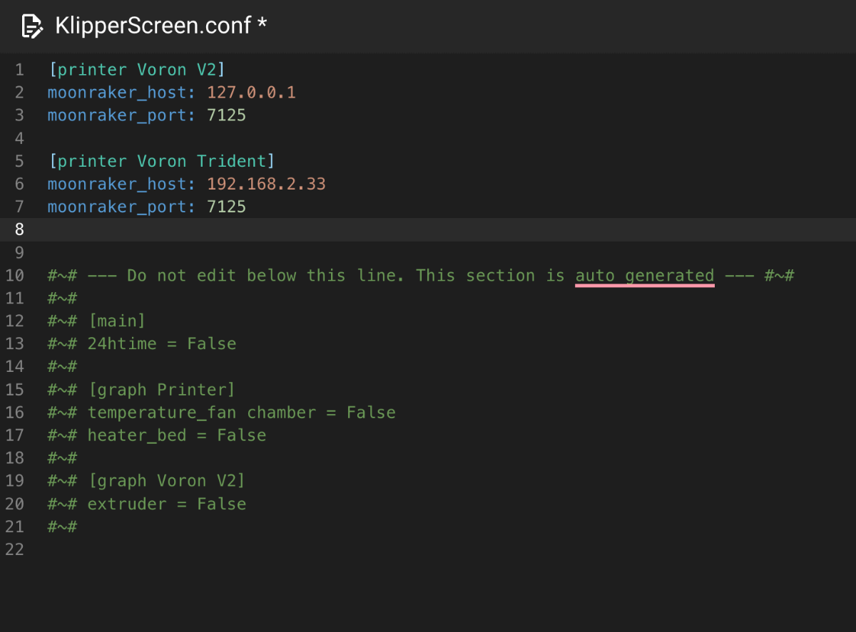
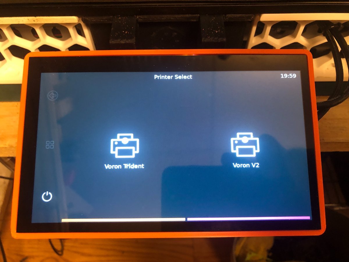
This could be a handy mod, the configuration is done in KlipperScreen.conf. moonraker_host: 127.0.0.1 is the printer that the screen is installed on. The IP address of the printer you want to add is listed below. When the printer boots, it shows you which printer you want to access. If you want to return to the printer select screen, use the double arrow.
5 points
-
There's some wonderful new filaments on the block... Fiberon by Polymaker! So far, I've tried two of them... PET-CF17 and PPS-CF10 Both of these filaments are very stiff, temperature resistant and dimensionally stable. They are also considered abrasive filaments, requiring the use of hardened nozzles. Here's my findings: PET-CF17 Fiberon PET-CF17 is a good choice if you have a standard hotend with a conventional Thermistor, rated up to 300C. Prints come out well at 270C though the surface finish wasn't great for me with a 0.6mm nozzle. The filament is quite brittle and needs a gentle filament path with no sharp bends. Warping is absolutely not an issue and prints are dimensionally stable and quite strong. The strength and heat resistance can be improved with post-print annealing at the cost of added brittleness. Like most filaments, PET-CF17 will burn if ignited.... it does not self extinguish either. This is not a cheap filament, going for about twice that of common filaments. (currently about $25usd for 500grams) PPS-CF10 Fiberon PPS-CF10 is a great choice if you have a high temperature hotend with thermistor / thermocouple / what have you/ rated to at least 350c. I upgraded to Revo High Temperature PT1000 which is rated to 400C. As with the PET-CF17, the surface finish was poor at 0.6 but pretty decent at 0.4 with a tiny bit of stringing.... perhaps some settings changes might help. Again the filament is brittle and easily snapped, maybe slightly less so than PET-CF17. Again, absolutely no warping and parts are dimensionally stable and quite strong. Post-print annealing can improve strength and temperature resistance (to 250C!). Breaking a part does not seem to favor layer lines when printed at 330C . If you drop a part, it sounds metallic! And, here is why it is my new favorite: This stuff does not ignite! I cannot get it to even start burning a little with an open flame... it just melts and smokes a bit. PPS-CF10 is very strong, has great layer adhesion, great dimensional stability, very high temperature and chemical resistance and all for the low, low cost of roughly quintuple that of common filaments! (currently about $70usd for 500grams). Sign me up for more because I cannot conceive of printing ANYTHING to do with a 3D printer Hotend or any structural part inside of an enclosed printer out of anything else at all. Printed parts do seem a bit lighter than ABS parts though I have no direct comparisons handy... yet. Comparisons are upcoming as I'm currently printing out Stealthburner Printhead parts. Because I was curious, I tested PPS-CF10 for electrical conductivity, and it does not conduct even when measured with a capacitor leakage tester rated to 1.6GΩ @27v, (that's 1.6 Giga ohms!) as opposed to a standard ohmmeter's range of 50MΩ at maybe 9v, which likewise reads "infinite" resistance. Happy Printing!5 points
-
I forgot to add. The older I get the faster I was5 points
-
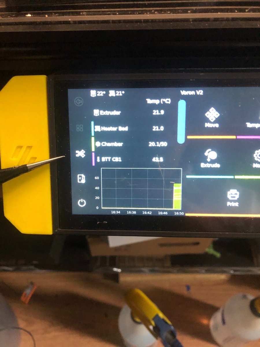
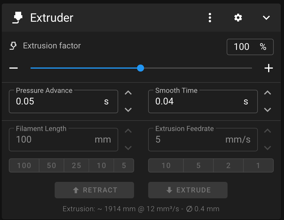
Thank you, everyone, for the reply. It turns out the pressure advance in the filament section in Orca got unchecked. The 0.05 was what I was seeing in the Klipper Extruder IU section, which is the default from the Klipper setup. All prints are back to normal.
5 points
-
Retired mechanic looking to hang onto the skills learned over 30+ years. Always enjoyed the diagnostic part - - once you know *what* is wrong, fixing it becomes the easy part! 3D printing is definitely exercising those skills! I've had to learn several new ones as well, starting with CAD (using mainly FreeCAD), "programming" of sorts in learning how to flash new firmware, then dumping that as too troublesome and shifting to Klipper and an entirely different set of issues! Like it a lot better than Marlin, though! Machine started as an Ender 3, quickly started changing things: quieter board (SKR mini E3 v 3, after toasting a v2), dumping all the noisy fans in favor of Noctua silent fans (and adding a dedicated 12V power supply to run them), adding a second Z stepper, trying various configurations of direct drive and hot end setups, most of which has issues with heat creep. Last outing was a HeroME setup with dual 5015 print fans and a V6 hot end, which worked well enough but really didn't meet expectations. Had Voron envy almost from day one (I'll get there one day!), and got parts for the Voron Stealthburner print head, retaining the V6 hot end for now. Added a linear rail to the X-gantry. Added drag chains for the bed, the X/Z gantry, and eventually the X/printhead as well. Didn't print them, just bought 'em from 'zon. Did print the "anchors" for the chains, first thing I ever used CAD for. Went for the "barf" LED lighting for it (beneath the Voron logo). kept the V6 but added a PT1000 thermistor. Not running YET but I'm knocking down issues as fast as I can find them (often with input from here!) Finding good information isn't always easy, and I've found that this site is one I can count on for good, accurate, and *complete* information, which is more than I can say for many, and has become one of my top "goto" sites. I appreciate your being here, and am happy to be a member!5 points
-
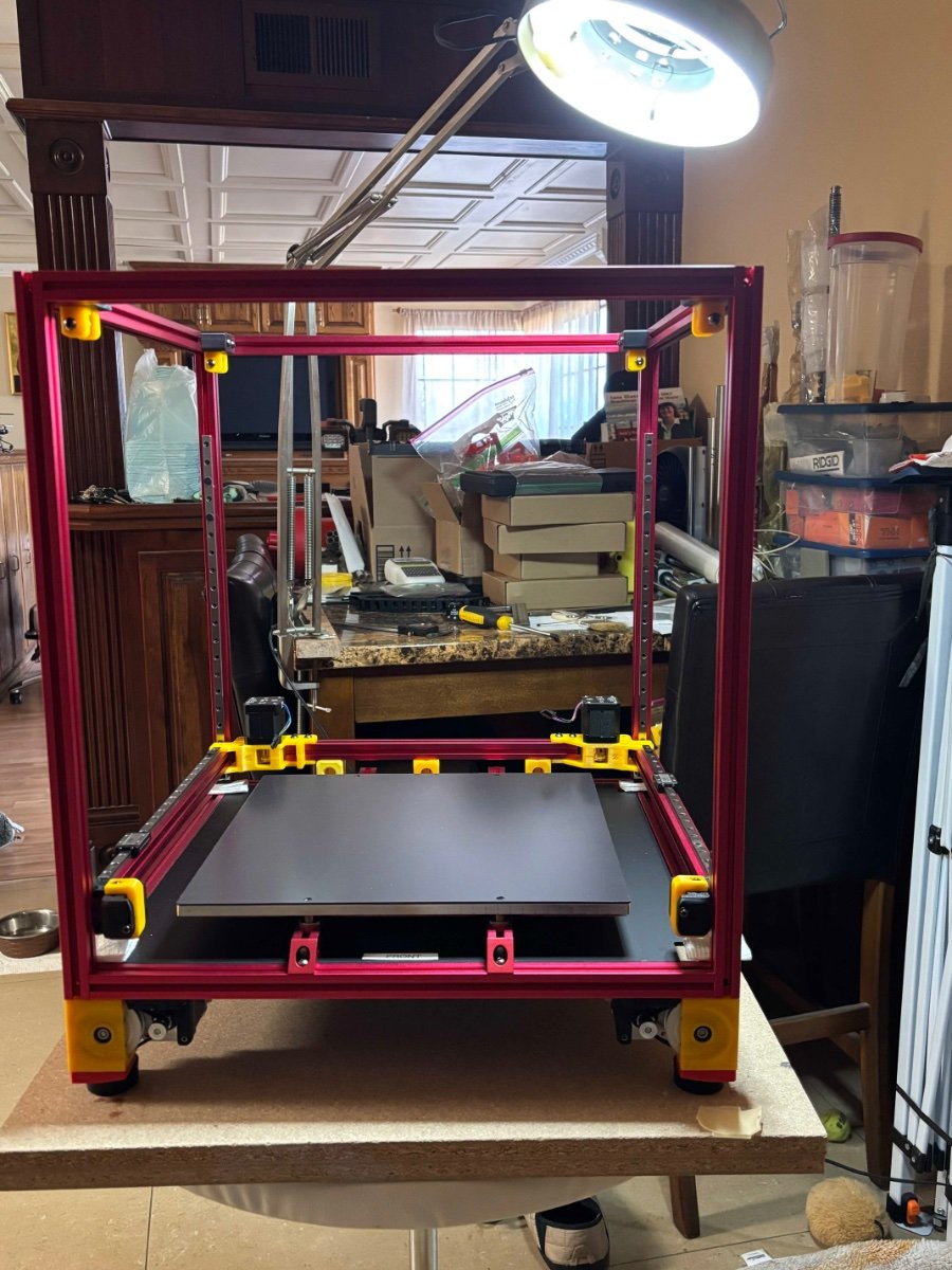
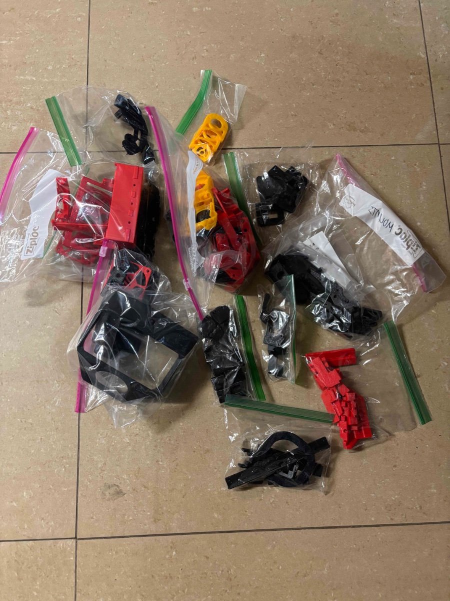
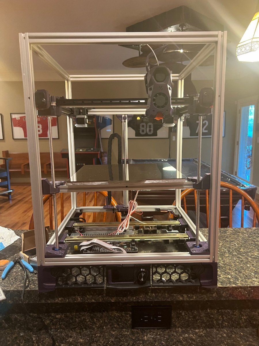
So I wanted a bigger 3D printer. SO I read about the Voron 2.4 build it your self printer. Looking at the well prepared Instruction manual, seems doable for me so I got the LDO 2.4 R2 RevD full kit. So far, other than a bad SLR12H linear bearing/rail everything seems pretty good so far. I have build it up to installing AB Idlers, now waiting for the replacement SLR12H. While waiting, I am printing all the parts needed for the build.
5 points
-
Received the serial number for this build yesterday.... This build I suppose is now officially over.. but tuning and mods will be never-ending ha ha.. On to the Next...5 points
-
I've just done something silly - I've bought a Fystec Doron Velta kit. It'll be a real slow burner this one. I've always had an itch for a delta.5 points
-
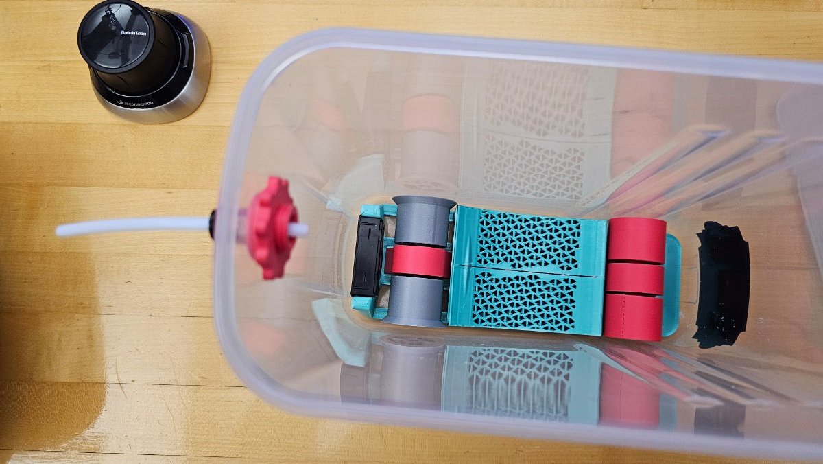
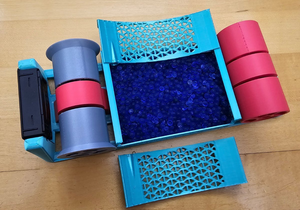
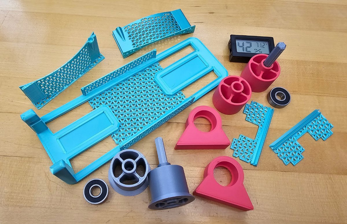
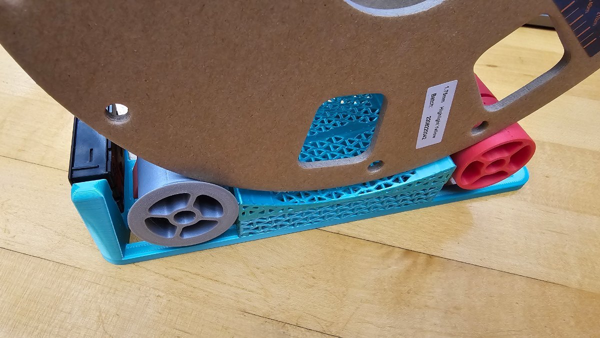
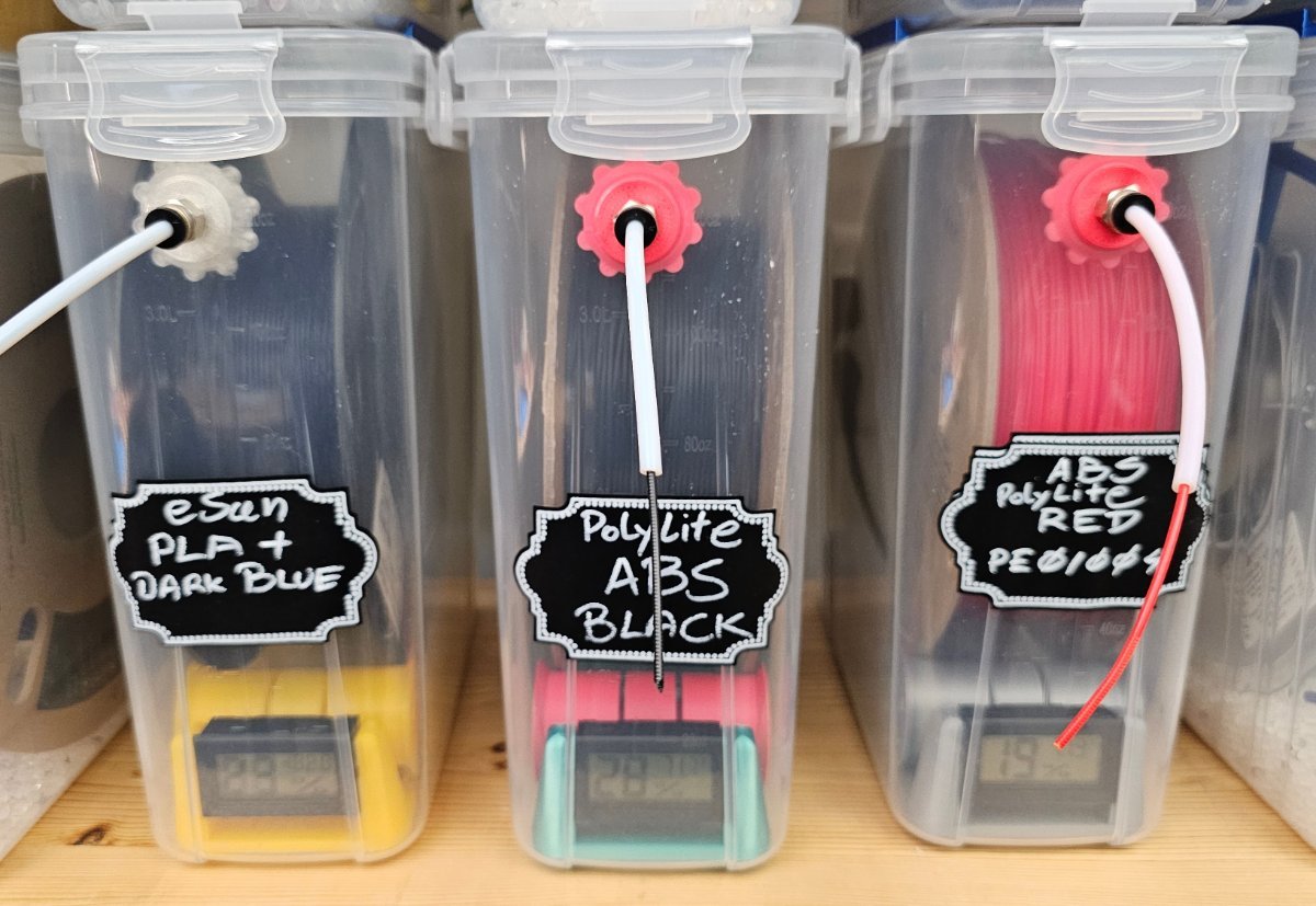
I have tried a few different filament storage/dry box designs for individual 1kg spools, and I believe this version covers my filament storage/dry box needs. There are many difference versions out there; this is my original interpretation. Also, it had to incorporate a fully enclosed but can be opened container that will hold about 100cc of silica gel beads. No supports required, just some CA glue for the small walls. With dry silica beads, I get about 10 to 15% humidity reading. Used the following besides the prints: Smallest possible airtight cereal container to hold a 1kg filament spool. Use only 2 608-2RS Ball Bearings per storage box. Small Digital Electronic Temperature Humidity Meter Standard size bulk Blue Indicating Silica Gel Beads. Bowden Tube coupler
5 points
-
I went sensorless when I upgraded my v2.4 (and I'll do the same in my Vz330). It does take a bit of tuning in but so far I've had no issues. There is one bonus to sensorless, once you've found the threshold and set it in the cfg. If it then starts stalling when homing the X or Y (mine did on the X axis) you need to check that everything is mechanically sound - my X rail needed cleaning and re-oiling (I'm no longer greasing my rails - I don't like sticky balls).5 points
-
No, I am not working away. I have a cottage in the country (30 min out of town) that is where my “stuff” is. We are there most weekends from about Thu evening to Monday morning. So, between stoking the fireplace and cooking, I get to do my techi stuff then. At my house in town, there is not time nor a good place for my “machines” This weekend, our son heads back to BC to university, so my wife put a prohibition on “personal time” - LOL , IT IS FAMILY TIME. In general, we are both “Makers” so no issues, she enjoys my laser cutter and 3D printer products too! Many a useful gadget is around the house.5 points
-
The Clockwork 2 files are not located in the V2.4 repo anymore. The CW2 and Stealthburner toolhead has its own repo https://github.com/VoronDesign/Voron-Stealthburner/blob/main/STLs/Clockwork2/Direct_Drive/[a]_latch.stl5 points
-
I have been debating starting a voron build for a couple years and have always found other things that occupied my time and money. A couple months ago I realized that I had a bunch of points racked up on slickdeals.net from using their platform to check for coupon codes. I always double check with their browser plugin to make sure I'm not missing any promos when buying computers for work. I never realized that I was racking up points which have added up to almost $500 while just trying to get better prices for work computers. anyway, I'm not sponsored by them to say that or anything, I was just surprised to have it out there to cash in on Amazon giftcards. I had an Octopus 1.1 sitting around from when I thought I might build an IDEX printer and never did. and I had a bunch of 2020 T slot sitting around from building a CNC machine and buying a laser engraver with a 1.5 meter square t-slot table and supports. So I had the frame and main board covered as well as a bunch of screws and other miscellaneous motors, wires, gears, and belts. I sourced most everything from Amazon or my basement pile of parts. My Amazon BOM is: BTT sb2209/rp2040 CAN on the Stealthburner CW2. Chaotic Labs Tap 2 upgraded red lizard (knockoff dragon) hotend 350mm linear rail throughout, because I had plenty of T-slot, so my Z is 50mm taller than the standard trident Mods: right hand power switch skirt trying to find a wire brush/purge bucket I like WAGO mount for fans in the skirt I found a CW2 main body where the PTFE tube goes all the way through to the extruder gears from the hotend for soft filaments, but it didn't work with the CW2 SB Main body for the CAN bus, so I'm working through that. I'm sure there are other mods and pieces that I am planning on, I just can't think of them right now. Thanks for everyone's help.
5 points
-
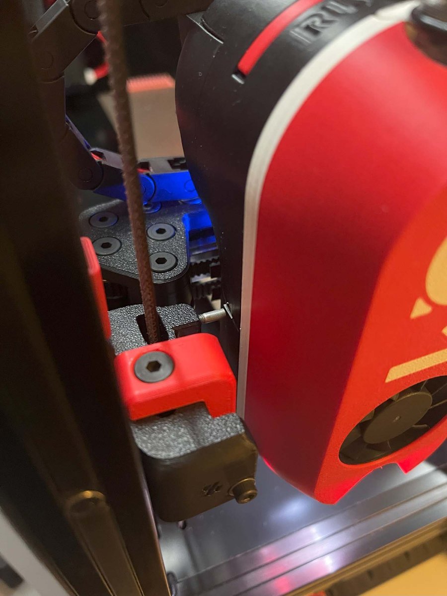
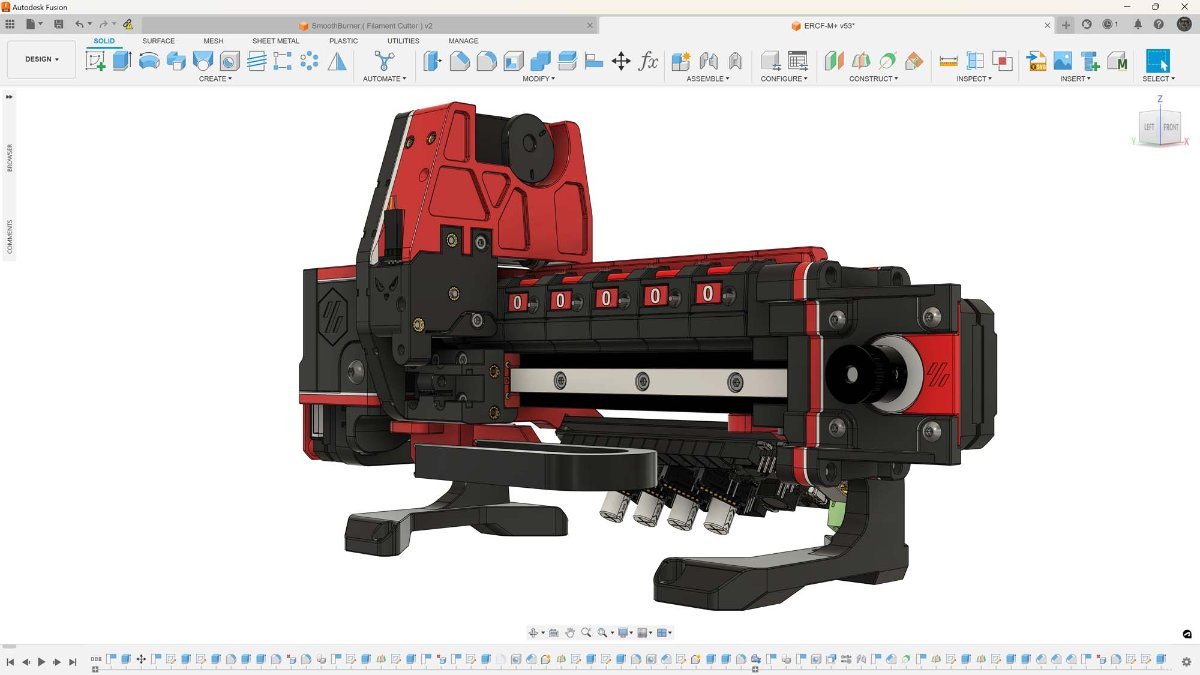
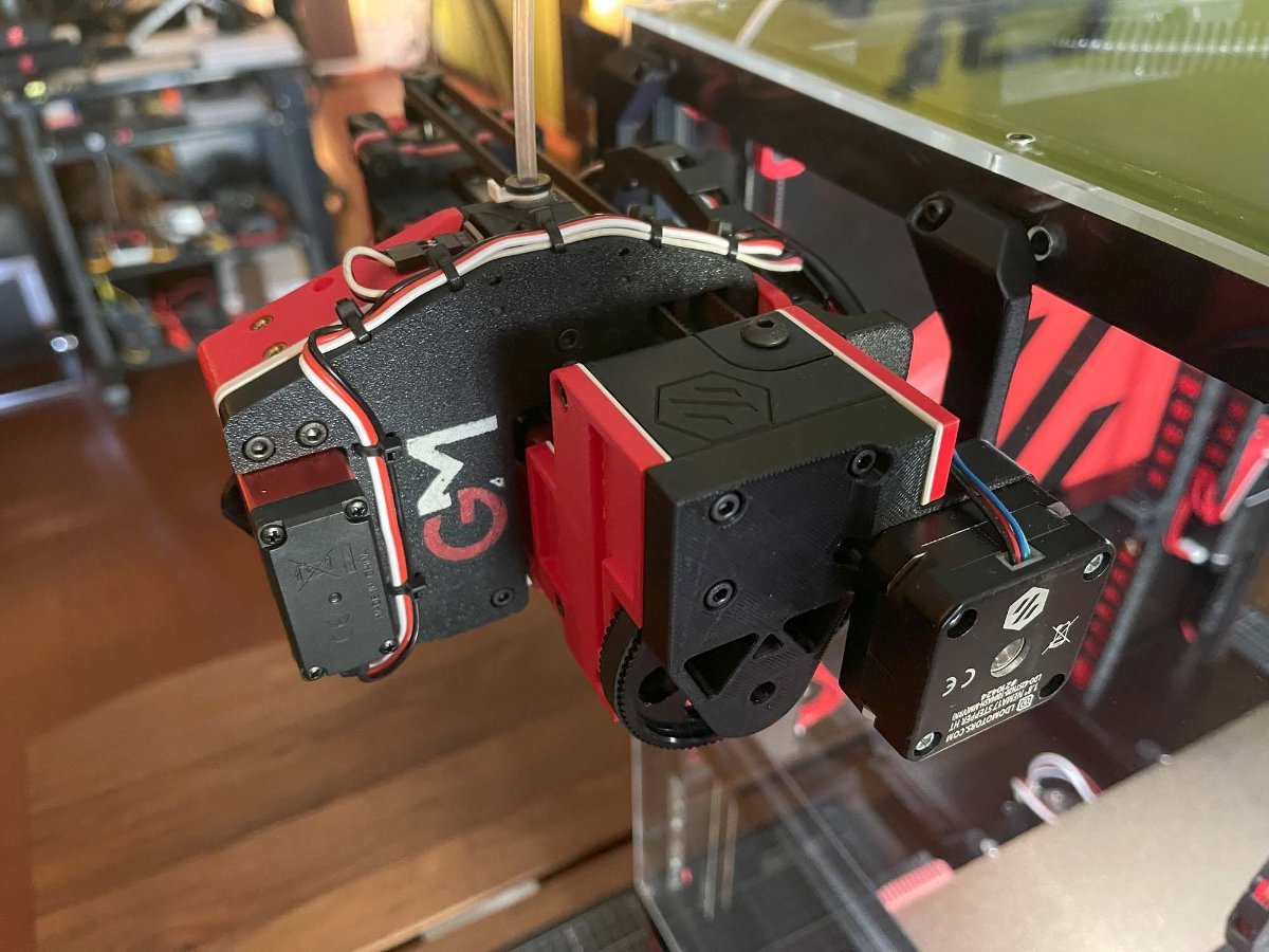
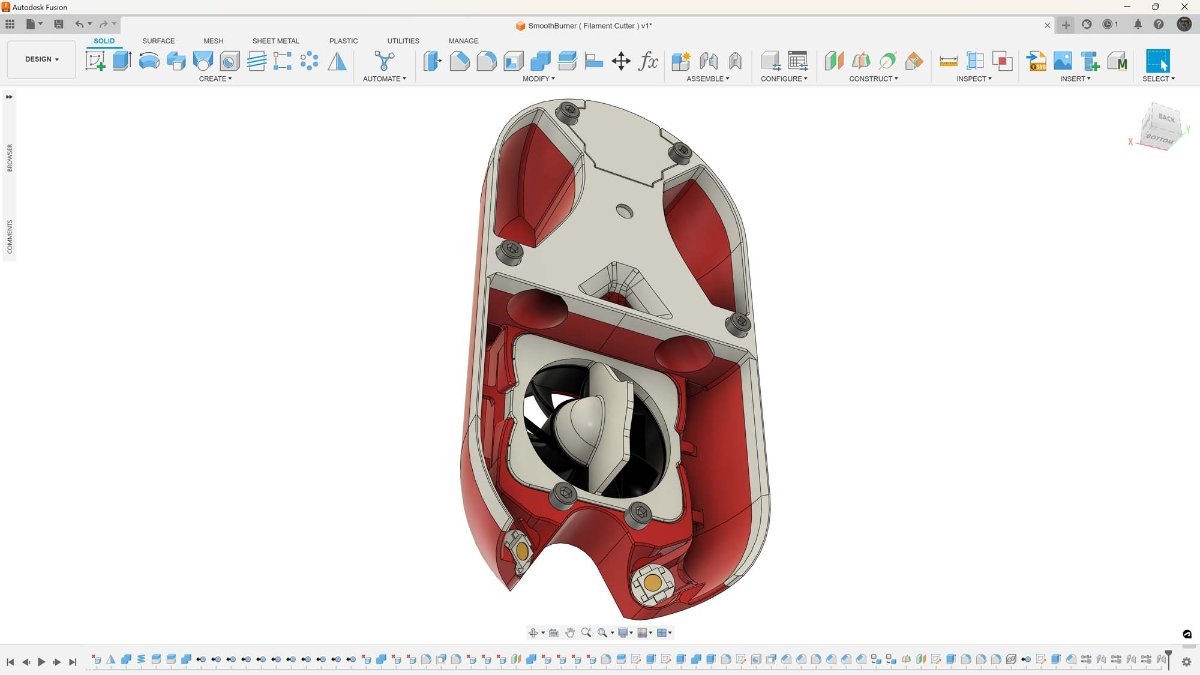
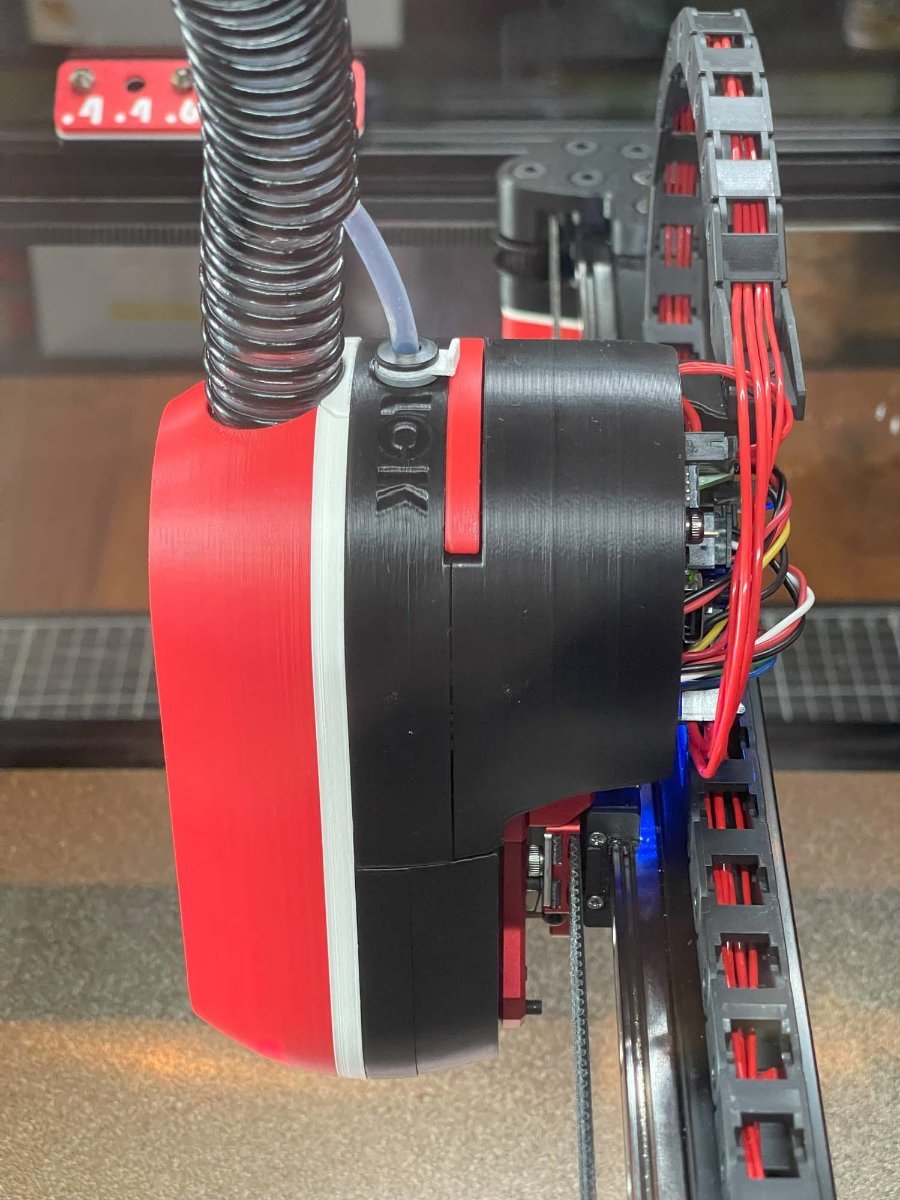
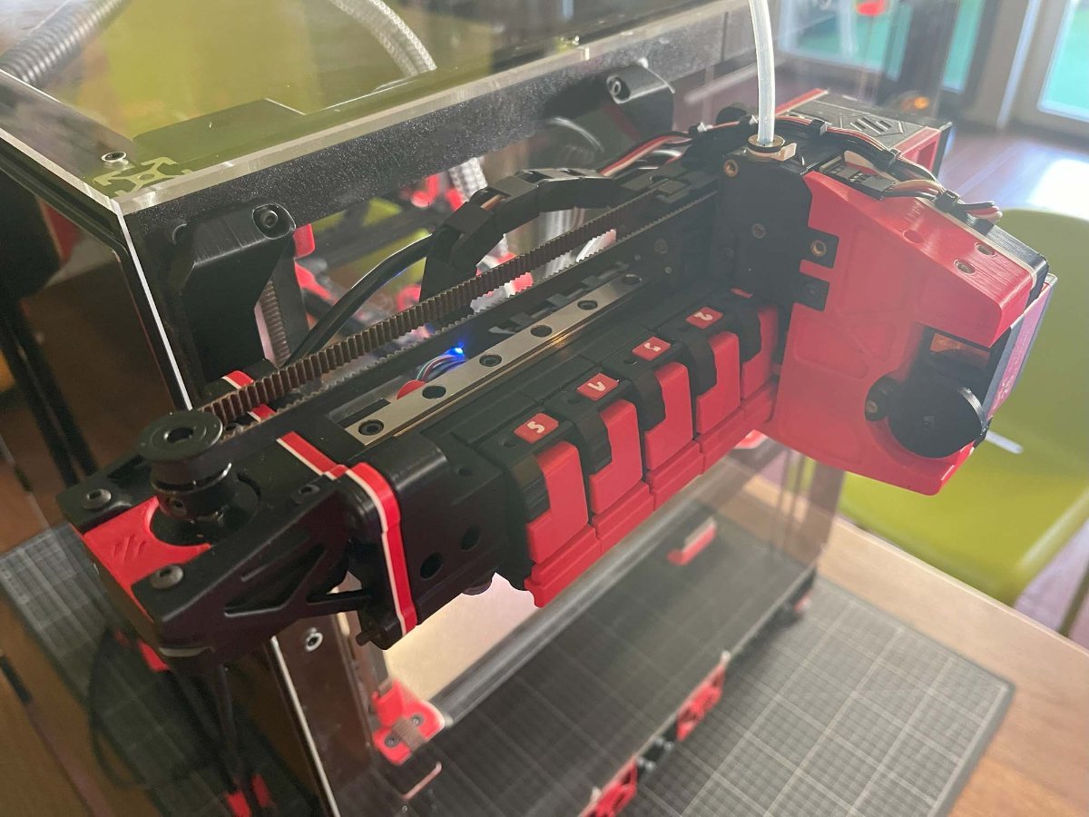
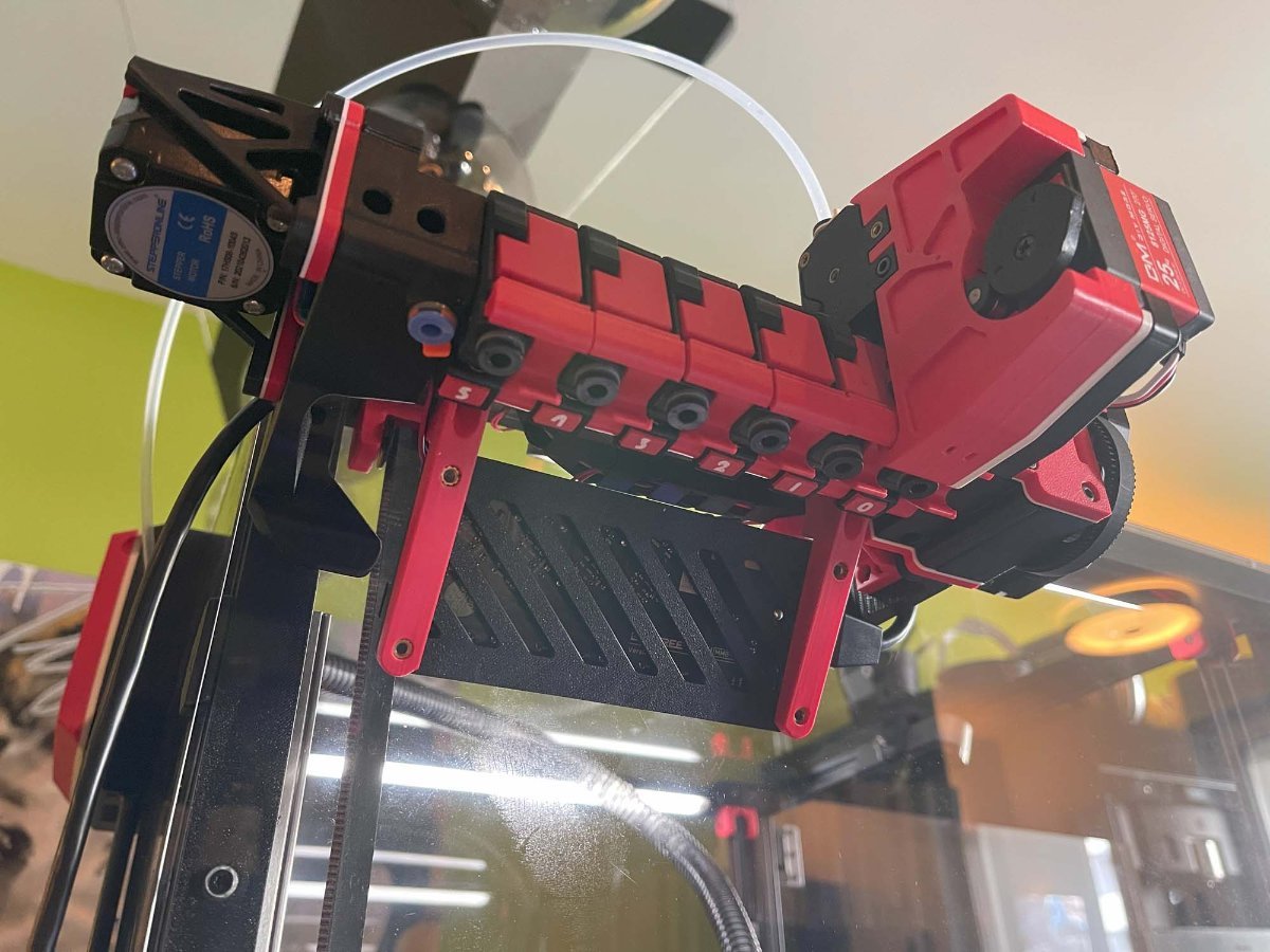
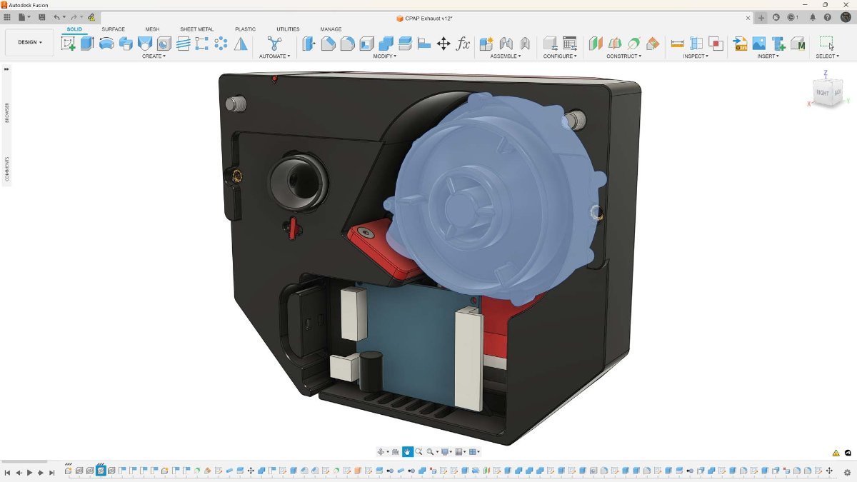
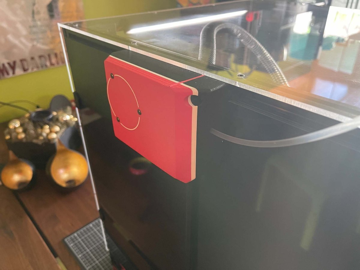
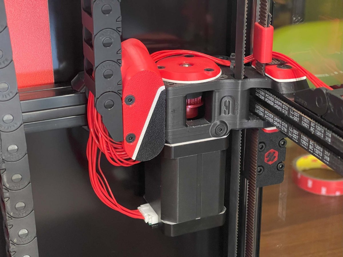
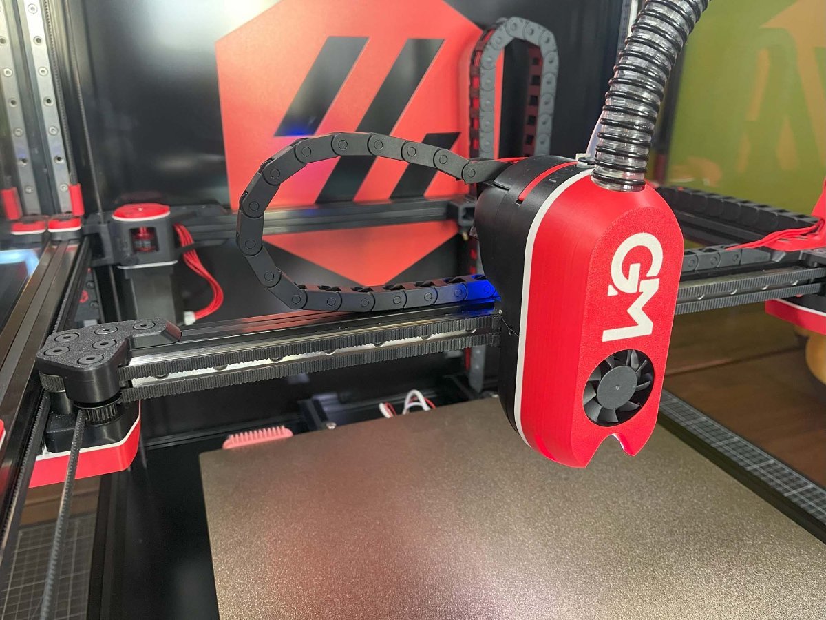
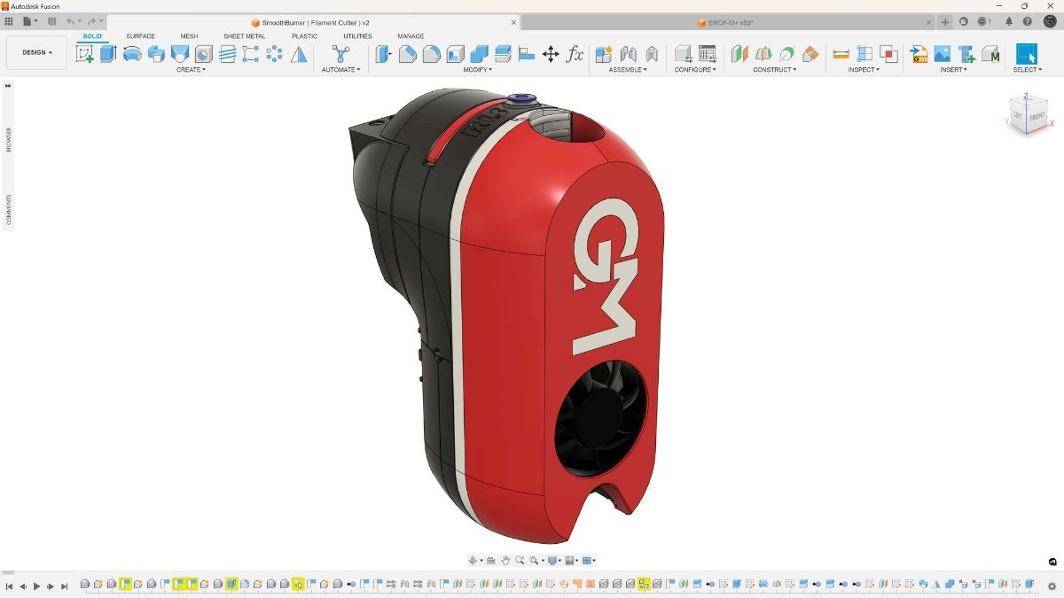
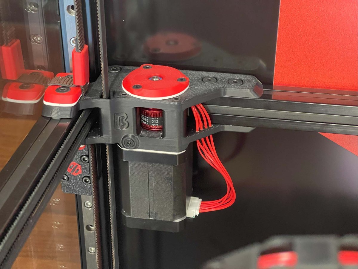
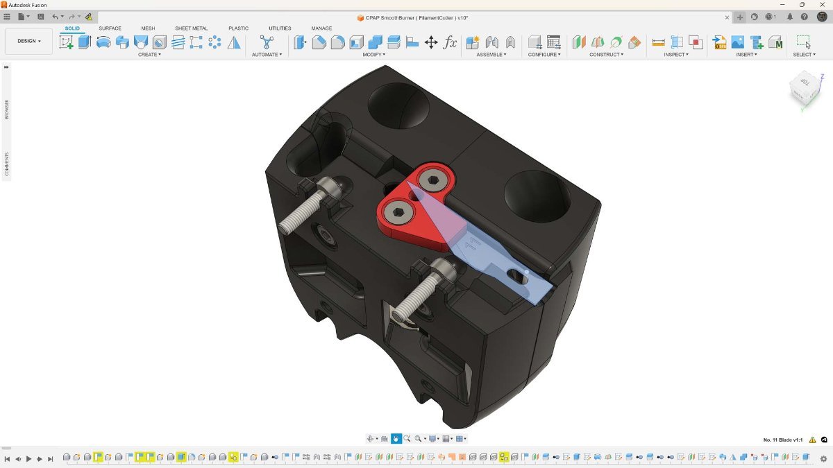
A Gallery of my 350 sized V2.4 Crystal Prison The Build started out as your run of the mill end of 2021 Formbot Kit but has gradually been upgraded with higher quality Components and mostly self-designed / redesigned MODs. A big part of the current concept was getting rid of the unsightly Panel Clips which I've done away with by attaching the 4mm Acrylic Panels directly onto the Frame ( with 3D Printed Spacers where necessary ) using Flathead Screws with the Sides overlapping the Top and the Door overlapping the Top and Sides for practically seamless Glass Cube look - Hence the Name Crystal Prison. The front 8mm Acrylic Door required additional CNCed Pockets for the flush mounted look of the three 90° Print in Place Hinges and recessed "Handle". All of the original Gantry Parts have been redesigned for a more streamlined look utilizing Ultra Low-Profile Socket Head Cap Screws. Meanwhile the SmoothBurner named Tool Head has been reconfigured to a CPAP Design without the StealthBurner faceted look I couldn't care for. The overall Dimensions and weight are slightly bigger than that of a StealthBurner but cause no issues with the geometry of the Gantry - As such there's no loss in Print Volume. The Front Cover attaches magnetically to the rest of the Tool Head via Screws being attracted to recessed Magnets with the former also acting as registration Pins preventing the Front from shifting ( the front can only be re/moved by pulling it towards the front ). The Wiring during assembly is a Pain in the Ass as neither the LEDs nor the Connectors fit through the Channels requiring Soldering within a partially assembled Front. Barely visible is the Tool Head Cutter Port situated behind the Front Cover and in-between the Extruder and Part Cooling Section. The Cutting is done by a Type 11 Blade with the Reset Function accomplished by a 1x40mm Spring Steel Wire sandwiched between the Part Cooling Halves. The in the B-Idlers installed Cutting Pin made out of a decapitated M3 Screw. The Reverse Bowden Tube exiting out of the CPAP Tube - While not yet fully realized yet it is planned to use this feature to keep temperature sensitive Filaments like PLA cool until they've reached the Tool Head while printing them together with high Temperature Materials like ASA. Also nicely visible is the red Filament Tension Lever for the Bondtech LGX Lite in its normal / centered position ( left being open, right being soft materials ). The Tool Head with the Front removed - Much of its design came from Eytecz LGX Lite Design featuring an ERCF necessary Tool Head Sensor utilizing a Washer / MicroSwitch Combo. New A / B-Drives for the LDO-42STH60-3004MAC (S40) "Kraken" Stepper Motors using 30T Pulleys - While not shown in these Pictures I've since had to add active Cooling Fans to them as otherweise they'd reach temperatures beyond their Insulation Class B rating. The new Drives also come with Shaft Support Bearings at the Top. B-Drive Side with integrated Cable Management Passthroughs routing them to the Back Extrusion Channel and to the A-Side ( covered underneath an Extrusion Channel Cover ). CNCed Minimal Clearance Z-Axis Belt and Cable Passthroughs. To the left a self-made High Temperature Silicone Nozzle Brush, in the center one of the two 8mm Bed Surface Alignment Pins, and to the right the Bed Heater Deck Panel Connector. A custom variant of the CarlosRodriguess ERCF-M but using my Large Servo MOD with the latter having enough force to break the Side Latch on the Original ERCF Design. Different View showing the Excentric CAM Wheel attached to the Servo operating a Spring-Loaded Stylus for a Springy like effect and my own Top Hat Design for the Kieraneglin Thumper Blocks. Underslung BigTreeTech MMB CAN Board providing maximum cooling and protection. CAD Model of the ERCF-M - I had initially only decided to redo the Selector portion for adding the Large Servo MOD but in the end went full retard and modelled everything. The CPAP Housing with the PTFE Tube being injected into it. The Housing houses everything and comes with the option to divert part of the Air Stream over the FANs Control Board by removing the small ( red ) Gate below the Exhaust Port. In a surprising happenstance the Housing paired with the thicker than usual Acrylic Panel seems to provide a fair bit of Noise dampening against the CPAP A short Video of it.
5 points
-
working perfectly5 points
-
Version 1.0.0
22 downloads
A Mount for installing a 5015 FAN ( like a SUNON MF50152V2-1000U-A99 ) with 40mm Hole Spacing to a 60mm Stepper Motor ( like the LDO-42STH60-3004MAC (S40) ) I tried using Double Sided Tapes and Magnets but neither of them were a reliable Solution so here's a Version that securely mounts it to the Stepper Motor without using the Stepper Motor Screws. BOM ( for a Set of two ) : 8x M3x4mm Voron Style Heat Set Inserts 8x M3x20mm Button Head Cap Screws 4x M3x12mm Button Head Cap Screws Print Instructions: The Parts come as Multi Color Parts for those that fancy it. I've used the usual Voron 0.2mm Layer Height, 4x Perimeter, 5x Top / Bottom Layers, and 40% Infill Settings which should work for anything using Heat Set Inserts. Perhaps use a Brim for the Air Guides since they barely make any contact with the Bed. Installation Instructions: Install two M3x12mm Button Head Cap Screws that will hold the Mount to the Stepper into the Fan Mount - It helps doing this while the Stepper has not yet been installed to gauge how far the Screws will have to be threaded into the Mount. Install the Voron Style M3x4mm Heat Set Inserts into both the Fan Mount and the Air Guides. Use the Fan to Assemble the Air Guides and Fan Mount into a unit using M3x20mm Button Head Cap Screws - Be mindful of a suitable Fan Cable Orientation that works for your Setup. Slide the Fan Mount onto the Stepper with the Screw closest to the Fan catching onto the Stepper Motors Bottom Plate first, then rotate the Mount so that the rear Screw will catch as well. ⚠ Caution ⚠: This was tested with a Chaoticlab CNC Tap V2.0 and no MicroSwitch Endstop Mount attached to it! ( Sensorless Homing! ) This AddOn may not work with any X-Carriers having Parts occupying the space below the X-Axis Extrusion as the FANs now partially do!5 points -
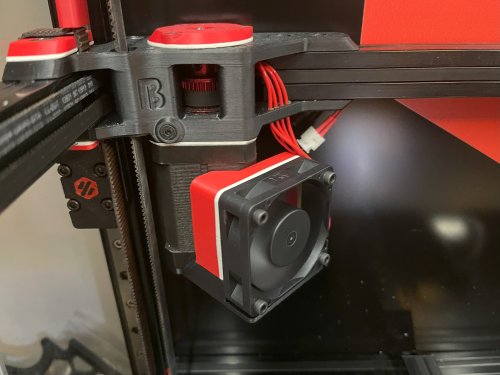
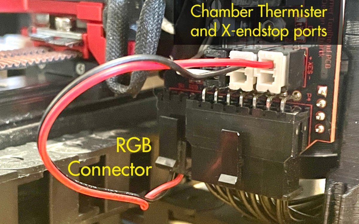
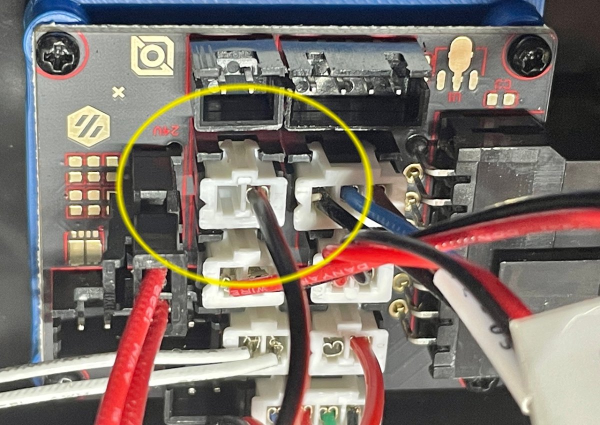
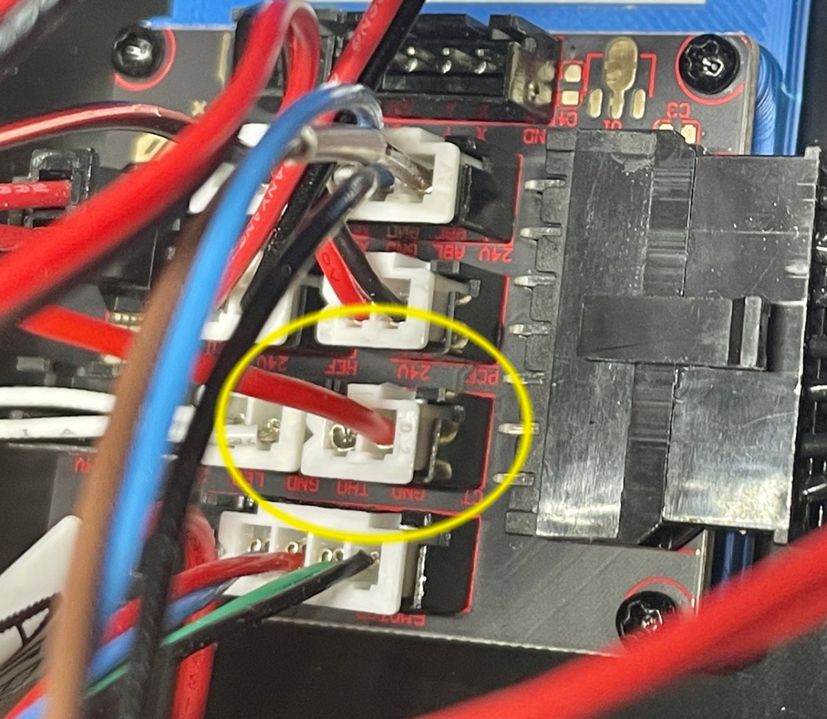
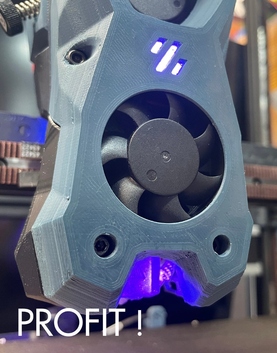
Sorry if this has already been covered elsewhere, but I wanted to share my experience with my new Stealthburner setup for my Voron 2.4 and how I wired it up. Key points to mention: I didn't want to add new wiring into the cable chain (lots of work and I didn't even have the wires to use anyway) I tested the LEDs ahead of time with a WLED ESP32 controller to ensure my wiring and installation of the head part works (link to that topic) I have unused ports on the PCBs that I wanted to use to avoid new wiring. Here's what I discovered going through this process: The docs recommend powering the LEDs from a 5V source, not the Octopus board Online folks talk about using the PB6 (BLTouch) pin vs. the PB0 RGB LED pin (center pin of the 3 pins) The PCBs use a common ground, which makes sense The Meanwell power supplies I used do not consider the case "V-", meaning you can't measure ground by connecting to the external metal case Most importantly, the 2 pin connectors for the X endstop and chamber thermister have one of the pins grounded (so you can't use both pins) So to accomplish this, I used the X endstop and chamber thermister connectors, but only one pin from each (since the other is ground). The ports were free for me because my X-endstop is on the gantry itself, and the chamber thermister is mounted elsewhere and connected to the octopus on it's own (without the toolhead PCBs). I just made an adapter cable with the RGB connector on one end, which splits into two different mini JST connectors. Note which pin I used for each. You can also just check continuity from ground to the pins to see which ones are grounded. I was able to use PB0 myself. So here is the final wiring under the printer: One pin from the breakout board connector goes to 5V on the small power supply for the raspberry Pi Another pin from the breakout board connects to PB0 on the Octopus board (RGB connector). Ground is already connected so there's nothing to do there. Hope this helps someone out there!
5 points
-
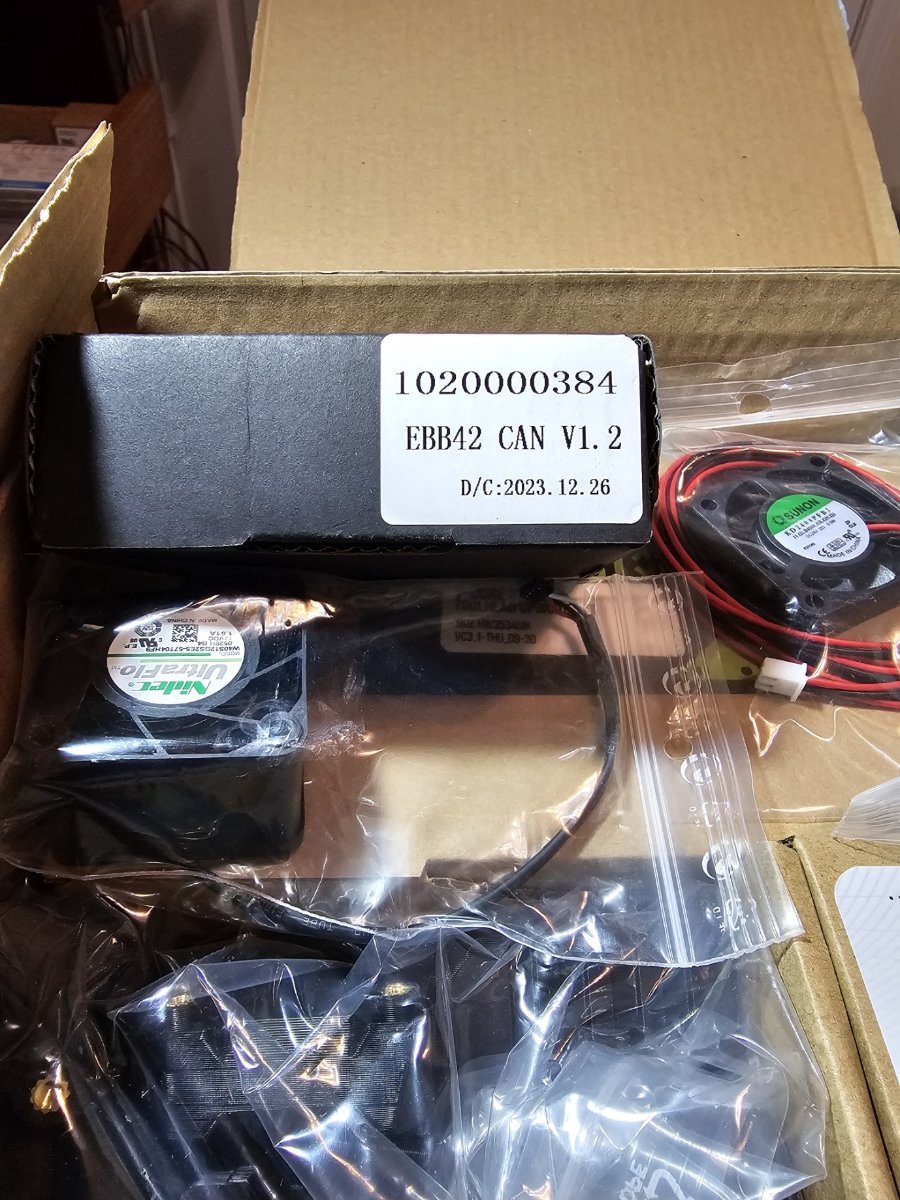
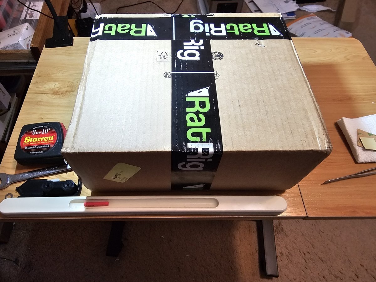
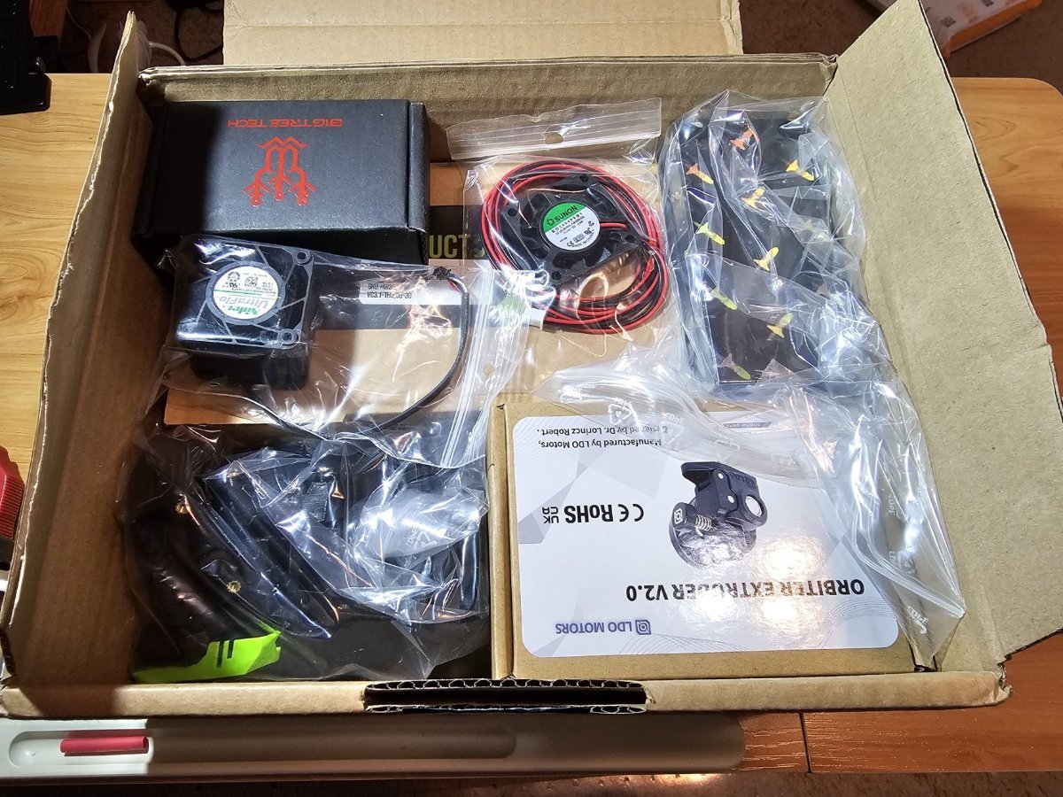
I found this at my door. Inside was all this stuff. ...and then there's this.
5 points
-
I love my CPAP setup. It allows me to sleep at night and reduces my wife's anxiety. Oh wait, you meant on printers...5 points
-
Version 2021.04.03
29,990 downloads
These hinges allow for 270 degrees of motion, from closed 0° to 270° full open parallel with the side panels. This was developed out of an effort of running into tolerance issues with the spec hinges not allowing much room if the two panel doors are used and are slightly cut larger by only 1 mm or so. I ran into issues closing and the doors hitting and needed something that allowed more horizontal movement. So it was decided to figure a way to mount on the side of the printer. After some searching, printing, trial & error, I came to what you see below. 270 degrees wasn't the initial intention but figured if they are going to be mounted to the side, might as well take advantage of the extra flexibility. During development and testing of these I struggled with tape being sufficient with my first version of these. So went back and designed these to use hardware and remove tape from the equation. Hardware mount was heavily influenced by Randell other door hinge mod that uses hardware. The handles in this mod are a remixed version of Randell's to adjust for the altered latch developed for this setup. The latch in the mod gives as much room as possible vertically if panels are slightly too tall. Note: Un-tested but the holes should line up with Randell's hardware for the hinges if you are looking to swap for more swivel. As you can see this setup allows vertical and horizontal freedom if your panels are cut too large. BOM Hinge Hardware M3 x 35 mm SHCS [x4] M3 x 8 mm SHCS [x4] Side Mount M3 x 8 mm BHCS [x8] Backplate. SHCS can also be used here. And if you want a flush look 8 mm FHCS M3 Threaded Insert [x8] M3 T-nuts [x4] hammerhead or spring ball, your choice Latch 3 mm x 6 mm magnets [x4] M3 x 6 mm SHCS [x2] BHCS screws work better here if you have them M3 T-nuts [x2] hammerhead or spring ball, your choice Handles 3 mm x 6 mm magnets [x4] M3 x 6 mm BHCS [x8] M3 Threaded Insert [x8] Printing Use the default recommended for Voron parts. Can be done in PLA but I have not tested this. If having issues printing side mounts you may need to add a brim to those and trim before installation Layer Height : 0.2 mm Extrusion Width : 0.4 mm Infill : 40 % Walls : 4 Solid Top/Bottom : 5 There is a left (a) and right (b), you will need to print 2 for each side. There are 2 versions of each of the hinge faces if you don't want a Voron logo or want to mix and match. Multiple depths are also provided. Should you need a specific depth and no access to Fusion, feel free to reach out to me on discord chrisrgonzales#0731 The 4 mm is typical 3 mm panel and 1 mm foam , and 6 mm files are for 3 mm panel and 3 mm foam. You will need to print 4 of the side mounts, they are not side specific. Assembly These are designed to have a tight tolerance, so the 35 mm screw can be screwed into the lower portion of the face hinge, and still have some play without wiggle. You will likely have to thread it all the way down then play with the hinge and pivot it a couple of times to work it in before attaching. Do not over tighten the screw as it will bind on the upper portion. If you feel it binding, back the screw off just a lil bit. When installing back plates to hinges to protect panel from cracking be careful not to screw down too much as insert depth is shallow as you may risk of pushing through. The backplates have a chamfer for more recessed look, but can be flipped if you have longer hardware. Take it slow when installing heat inserts as it's very easy to push them through and cause deformation on the face of the hinge. Set temp on iron lower than used on most other heat inserted parts as this gives you more time not to press through. Also you may have to use the side of your iron's tip as not to puncture all the way. For placement of drilling, you can install the hinges in place, and tape or use panel clips from sides temporarily to hold front doors and tape outline of hinge. Then remove the panel and hinge, place the hinge where the tape outline is, mark the hole and drill. CAD Files The CAD files are parametric! When opened in Fusion 360, editing the thickness parameter will change the spacing and geometry to allow the hinge full 270 articulation. Enter in thickness of your panel and foam, I would recommend accounting for the compression in your foam. Example 3 mm panel with 3 mm foam, typical 6 mm would be entered, but possible that 5.8 mm might be a better choice to give some compression for a seal. If you are unsure, printing a single bracket and testing fitment and offset would be ideal. If you would like to use this with tape only you may adjust the faceThickness parameter to be thinner but wouldn't suggest going smaller than 3 mm. You will also need to remove or extrude flush the holes for the brass inserts. Also the faceWidth parameter may be adjusted to be smaller width. Would not go lower than 27 mm for this parameter. The logo can be removed if needed. If using Fusion 360 with history, step back two actions and logo will be removed. Otherwise removal of chamfer and extrude flush will be needed. thickness : panel + foam depth in mm (default 4 mm) faceThickness : depth of the face portion of hinge not including panel + foam (default 5 mm) FacePlate_width : width of facing hinge from edge of extrusion to the opposite edge. Not actual width of hinge default (34.9 mm) Taped versions use 27mm. See image below. Questions / Suggestions If you have any questions or suggestions feel free to contact me on Discord chrisrgonzales#07315 points -
One last mod to finish up the project. Clicky-Clacky Door Mod. And... The printer is now in my office and printing beautifully. Printed parts... These were printed on my VzBot. Material Polymaker ABS Black, 5 perimeters, 5 top, 5 bottom and 30% cubic infill, no supports, no brim. Bed 110, HE 240, Outer walls and top surfaces 200mm/s 5K accel. All other walls infill etc. 250mm/s 10K accel. Travel = 800mm/s 20K accel. Print time = <3hrs I put all this print info up here because I'm curious to see how fast others are printing ABS. And of course, the quality is not bad.
4 points
-
You guys really suck, Ya know... Clicky-Clack door on order. Might as well finish up my refurb with a nice mod. I also ordered new top and side panels. The old ones had heat related fogging that couldn't be clean away. They're fine actually but for ~$40 I'm getting new ones.4 points
-
My experience is almost entirely with Revo; I do have a Prusa Mini+ that started with a standard V6 style hotend, but that's been updated with a Revo. I like how the Revo is designed overall. The components are modular, so you pick the cold side heat sink that will attach to your print head. The heater is self-contained and easy to swap out; so for example you can now easily switch to a high temp setup with the new 60W heater. The nozzle and heat break are integrated into one piece, so one seam and potential leak point is eliminated. The nozzles really are one hand swap. They are super easy to change out, no tools needed or worrying about proper torque. The only hiccup is that flow rate isn't as high as some other options. So if that matters it's a consideration.4 points
-
I have a 350 v2.4 and a pair of 300 tridents and a v0.1 and a Bambu. They all get used, occasionally at the same time. NEVER TOO MANY PRINTERS. Hi, my name is Rick, and i have a printer and filament problem…4 points
-
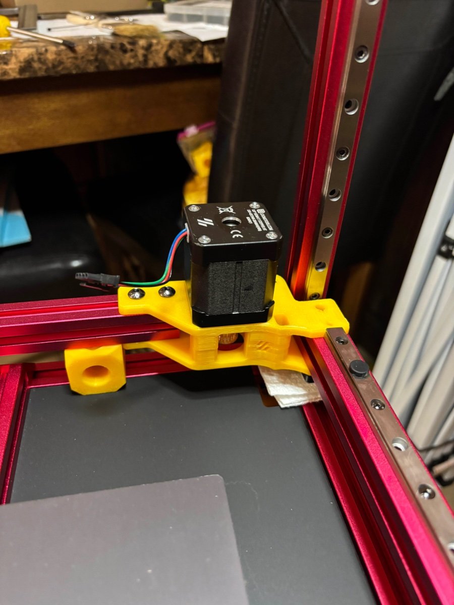
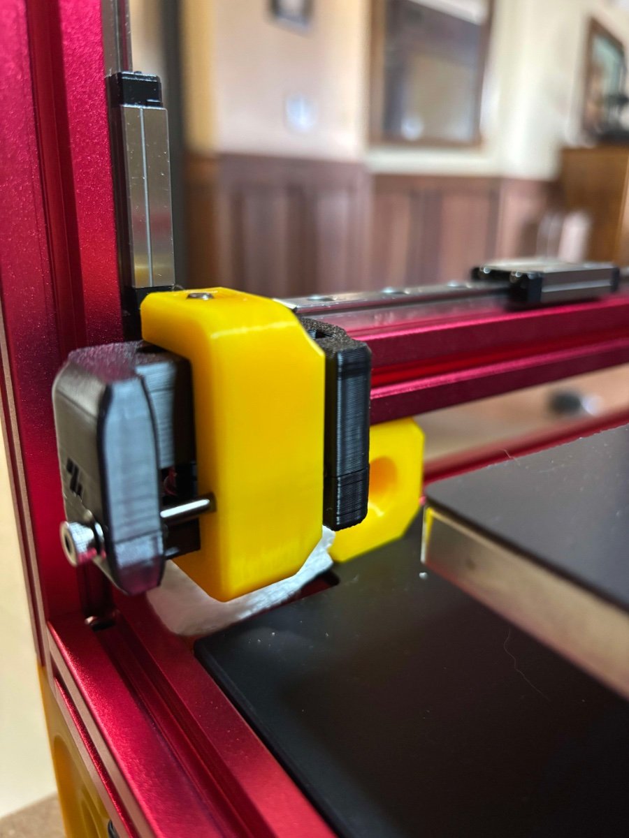
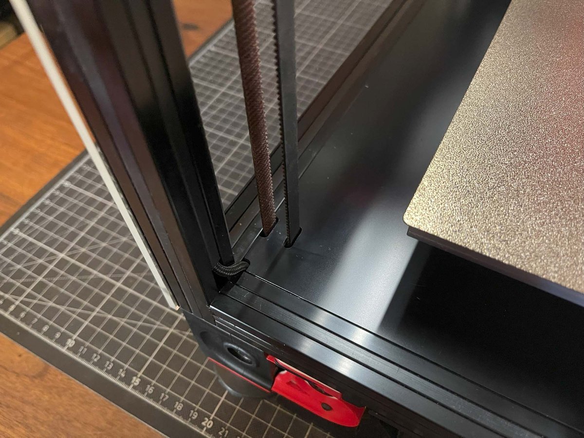
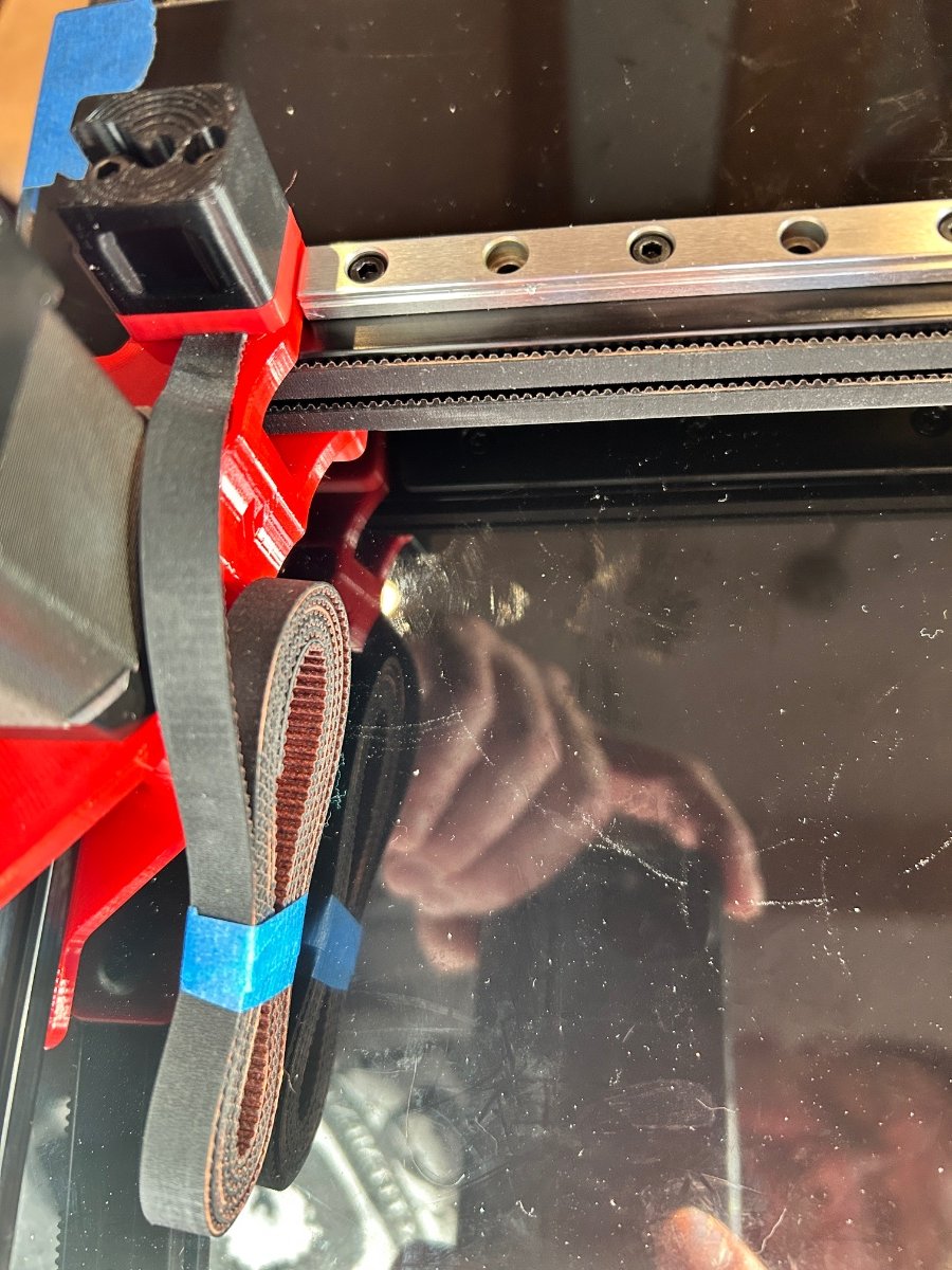
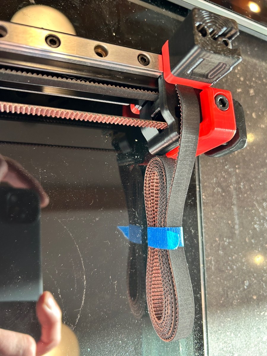
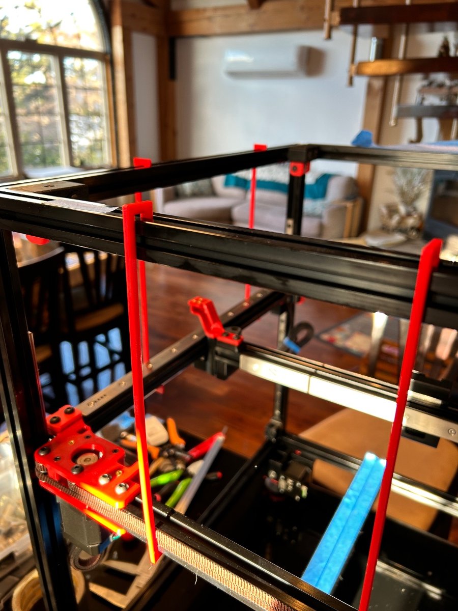
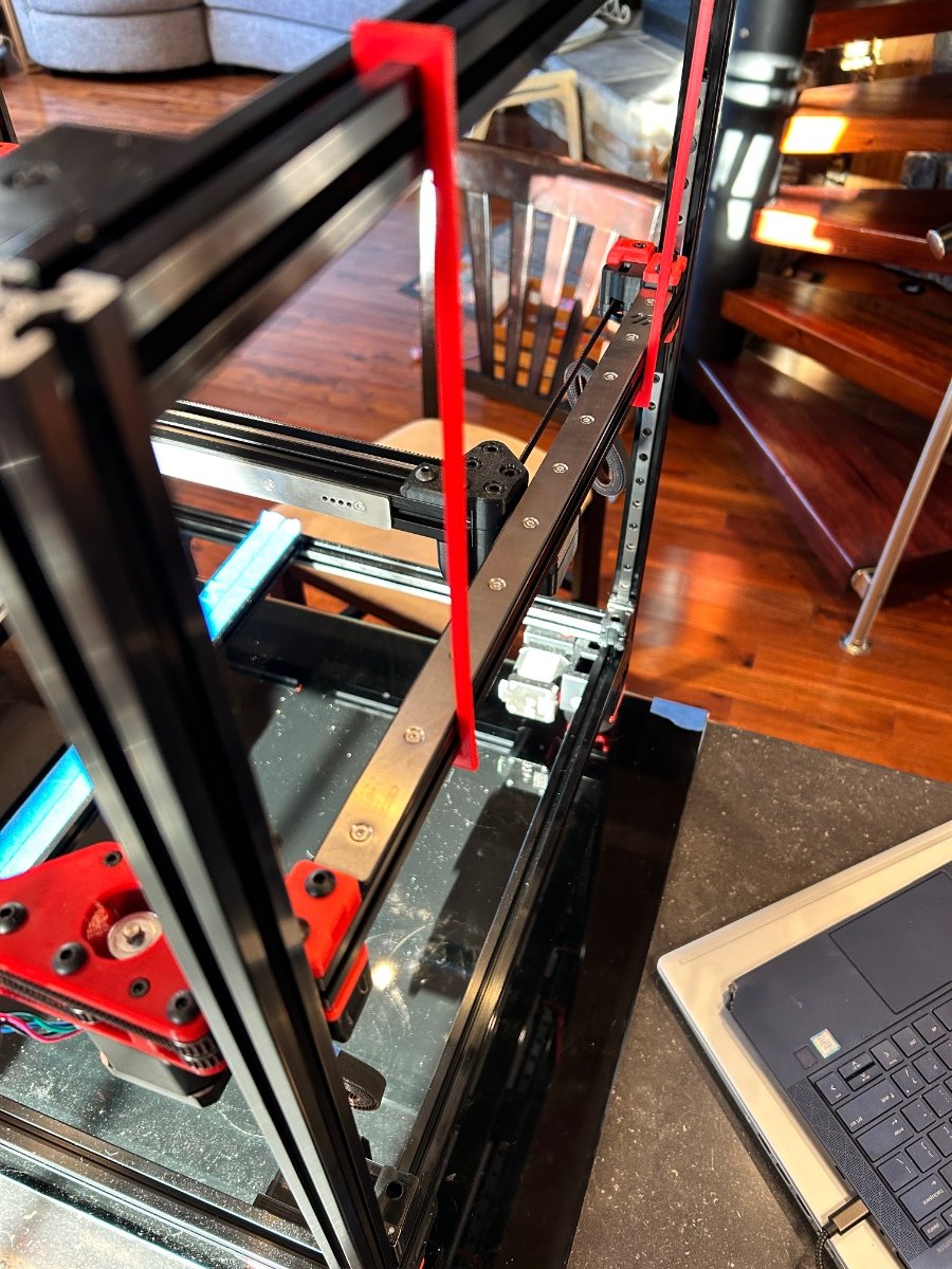
the last two days saw a bit of activity. I managed to “belt up”. The XY gantry went well. Before I did the GT belts, I attached the titanium backers described here: https://www.3dlabtech.ca/product/titanium-backers-for-voron-2-and-trident/?srsltid=AfmBOor3rNmbVSyywapTjKTXdG6jZZHczWwV6Es-DEyeZaE9MHLR20IF Way back when I was collecting all the parts (over a period of about 14 months) I saw this and decided to get it too. I hope they are worth it. I followed the guidance and use torques screws to tighten them realy well. The strining of the belts went well, no issues. I took the video advice and strung one AB belt completely, then removed it measured the 2nd belt to exactly the same length. The Z-belts also went on with no issues the tension came out out very nice and even without adjustments. Leveling and racking fells good too. The red brackets in the pictures are my “gantry hangers” I printed them on my exiting Prusa and made sure the fit over the lower linear rails and at the back of the gantry and hook onto the top extructions. I just choes 240 mm long since the longest part I can print on my Prusa is 250 mm. I think they helped Lastly, I started the toolhead assembly. I am missing a few parts like the pancake stepper motor so I had to stop. But the fillament feeder is good now. I assembleld and disassembled it three times but I wanted the feeder hole lined up perfectly. It feels good. I chose the Stealthburner and will go directly to CAN bus. I know some recommendation is to do the stock tool and communications first, but I enjoy this so to me it will not be time lost. If I get stuck with the various flashing of boards and setup, I can also go back to the drag chains. Time will tell and I will update here. Waiting for some parts now, so, If I get me aluminim base plate, I may be albe to do a bit of electornics mounting next while I wait for the extruder motor to show up.
4 points
-
Another thing could create filesystem issues is the SD card. I use Sandisk Ultra and after a couple of years they start to lose bytes. In production facilities using Raspberry Pi they configure the bootloader to use USB hard drives or SSDs. A nice article for How to Boot from SSD on Raspberry Pi. Happy New Year!4 points
-
I flew with Emirates on the A380, non-stop Dubia to Sidney - I lost the will to live at one stage. Then I met a troop of female real estate agents in the bar and got sh'tfaced.4 points
-
I've been itching for a MMU or whatever you choose to call it. This one seems to be the one for me, I think I'll be self sourcing it as I have a truck load of "spares" after stripping the TronXY down.4 points
-
Welcome to the meeting of Printer's Enablers.4 points
-
You're not helping...4 points
-
It's going to be an interesting weekend. and only 2€ import duty.
4 points
-
I do not want to get boring.. but when it concerns CAN, I would always check out the CAN Bible for non-chinese speaking, Esotericals. Check out this page. it shows EXACTLY what you want to know.4 points
-
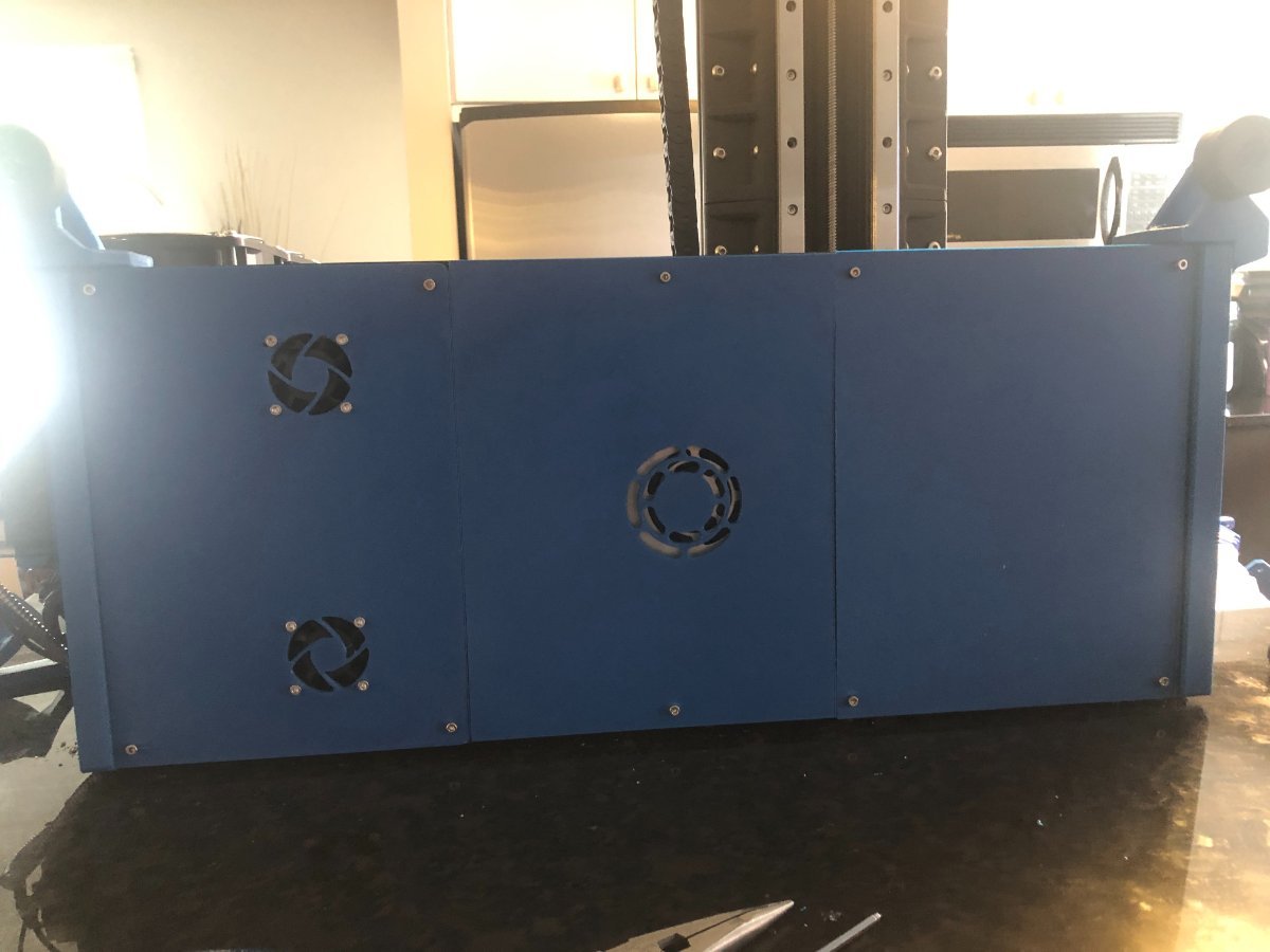
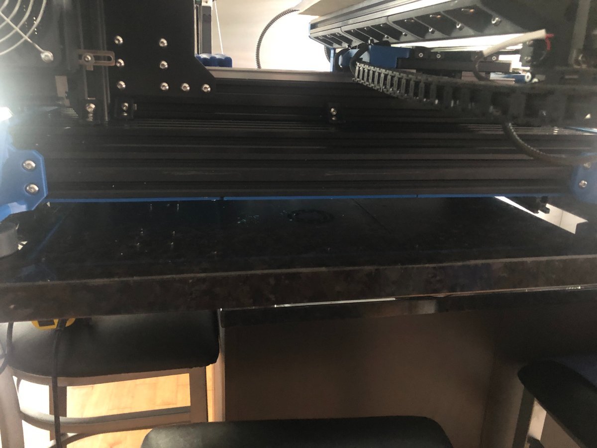
I thought I'd try this (3D printed panels) instead of having a bottom panel cut since it can't be seen when the mill is upright. Thanks again @Penatr8tor for designing & sending me the file from the bottom panel.
4 points


.thumb.png.ccacec25ec2c6981985cafe50328c3e3.png)