-
 8
8
About This File
This is an "expert mod" and should only be attempted if you understand the risks involved, which include:
-ruining your printer's frame, which means starting over your project... The mod requires you to drill through your frame. I suppose the cable could be routed outside but, hey, in for a penny...
-dealing with RF interference on the usb lines which may produce hard to detect issues: The Raspberry Pi is going to be housed with the screen so the USB lines need to be passed back down in the cable to connect the main board and the webcam: care needs to be taken here to reduce RF interference so it involves wrapping wires in foil tape.
also, the actual print is challenging because it includes aspects of 'print-in-place' that require good temperature tuning to succeed: the cover is printed in place with the main case and need to be broken out with tools after printing. If you are good enough to drill your frame, I'm sure you'll figure out the print...
I doubt anyone will try this one but I'm putting it out there given the amount of work this was to perfect. So I could go on with details but I'll stop here. PM me if you want build this and have questions.
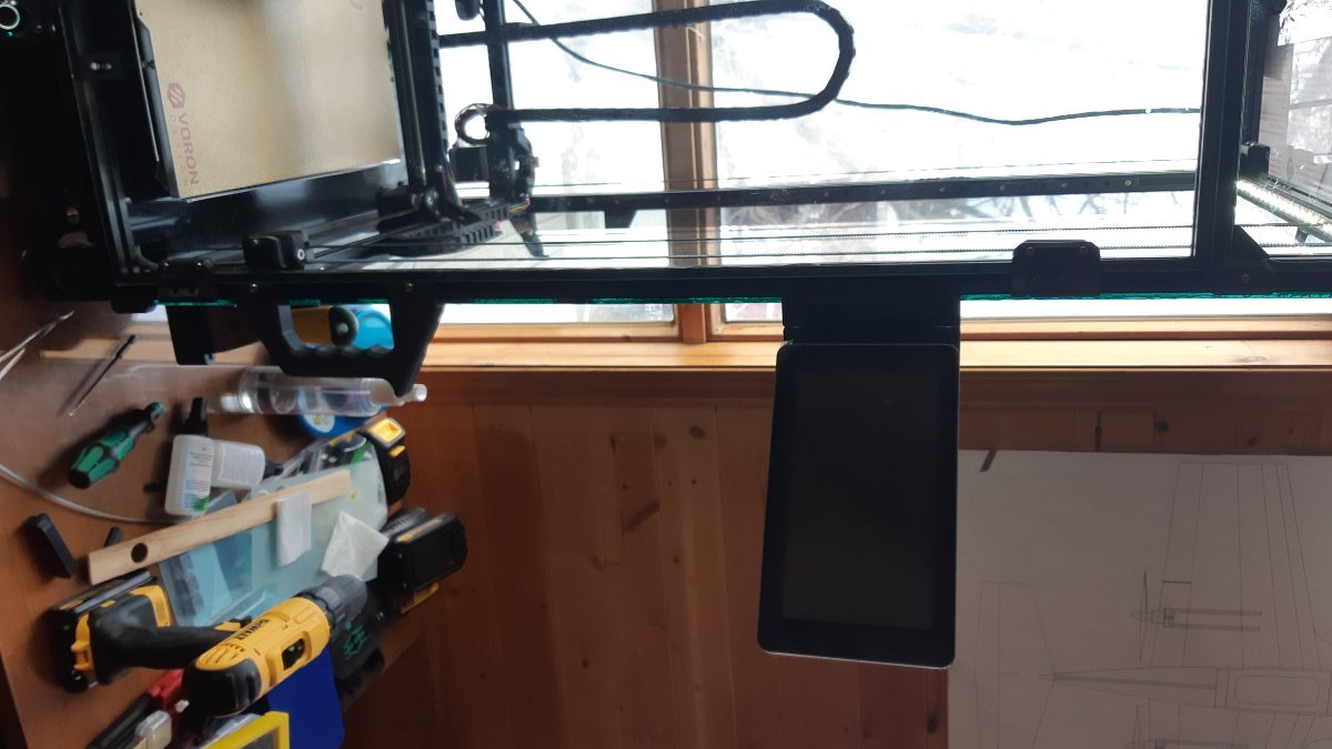
So for the uninitiated, a DRO is a computer you add to a machine tool to make it partly CNC and generally looks like this:
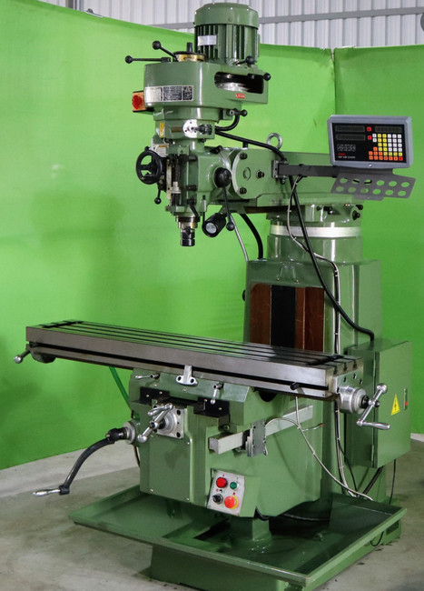
It is typically hanging around on the sides and most importantly, at eye level !
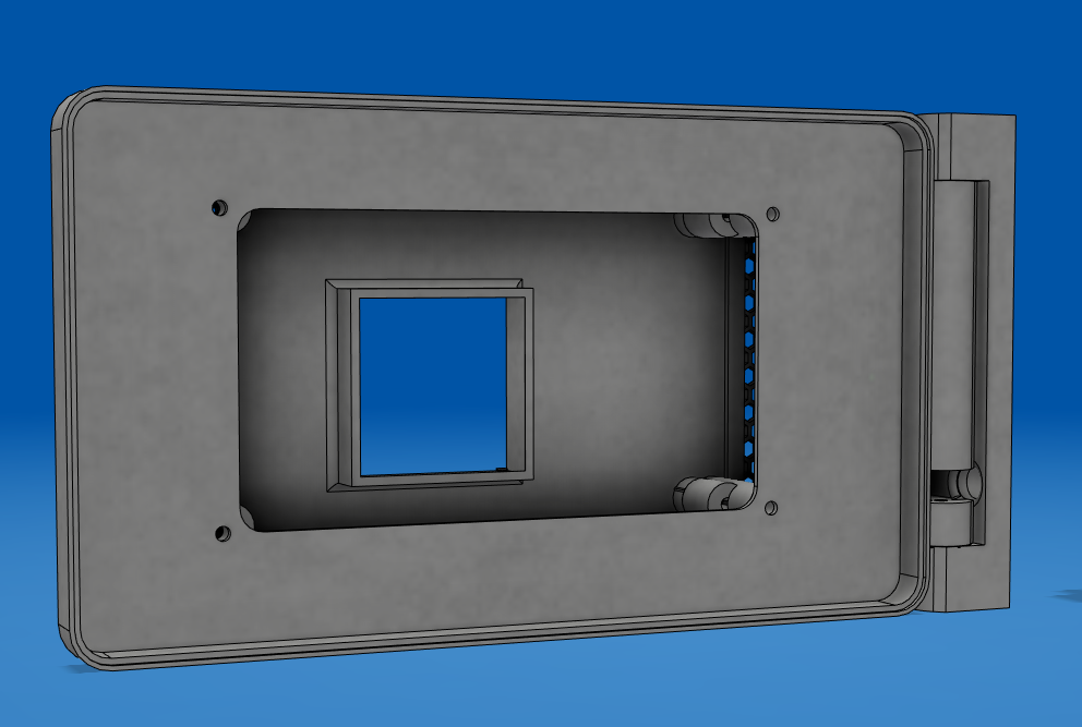
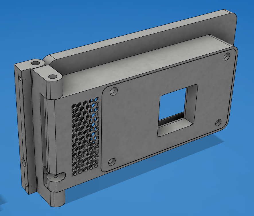
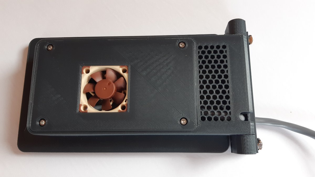
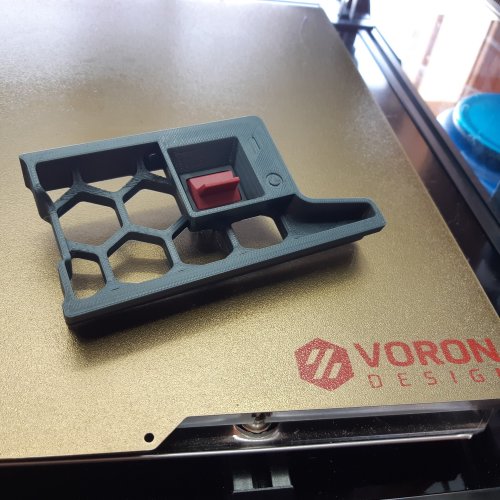
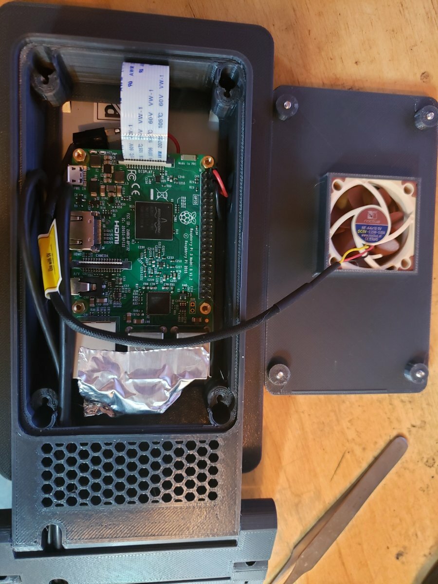
40mm x 10mm fan in fashionable brown  snaps in tight

ADDITIONAL NOTES:
On 4/8/2022 at 8:17 PM, Hock said:I'm going to have to try the DRO Pi 7" case. I've currently got a 7" screen on my V1, but it's in a normal case that's just sitting on top of the printer housing.
Wow, that's an honor, I hope you like it. Here is a bunch of extra info on that. did you look at the STL's ? what do you think of the print-in-place cover?
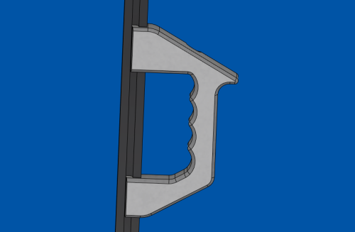
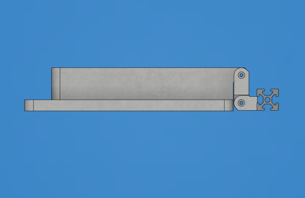
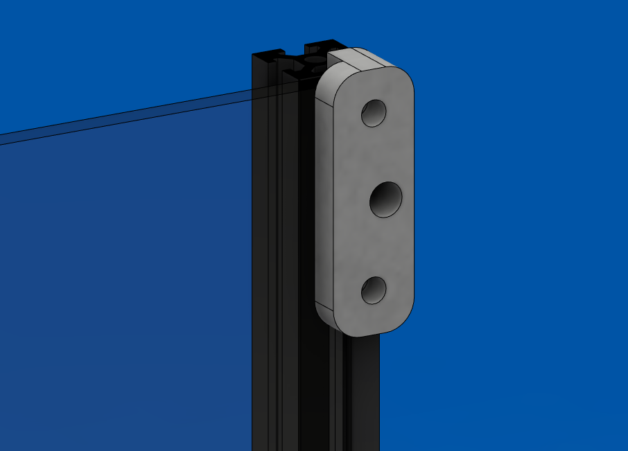
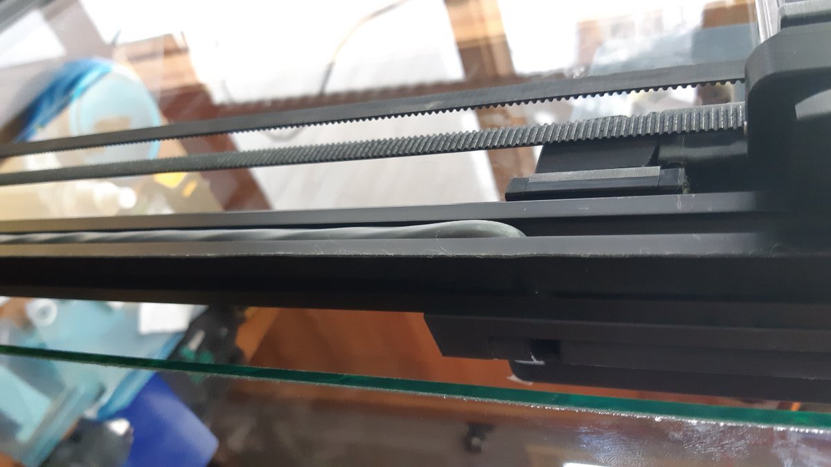
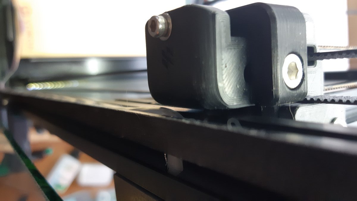
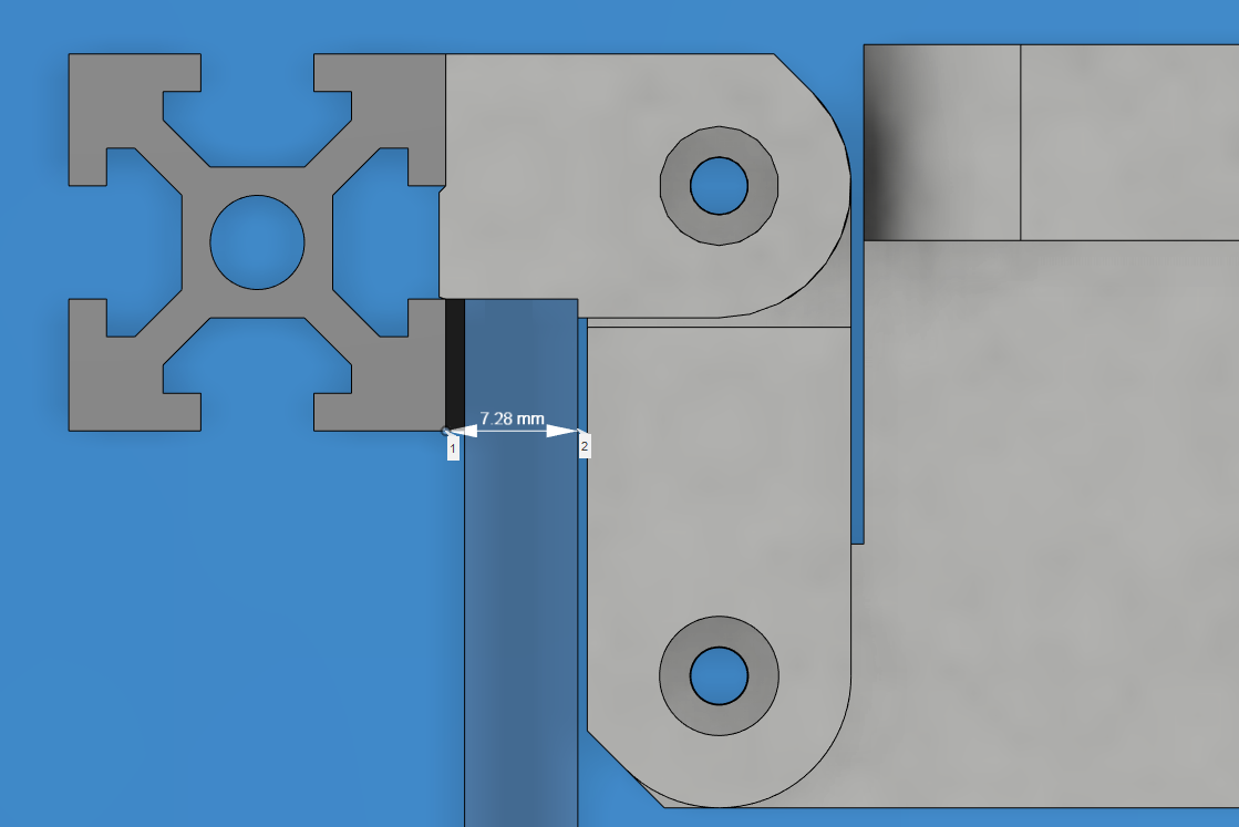
As it is now, the base piece is sized for my thick enclosure at 7mm. This can be adjusted:
Also, I did not test it yet because I'm waiting on parts to finish a bunch of peripheral stuff all at once when I put the printer out of commission. It should be next weekend. I'm pretty sure the Rpi will fit ok but I have a little doubt about the clearance between the fan and the pi's pins. I used drawings to figure out clearances but I may have did it a bit tight. The cover may need modifications but all the other parts are tested and working fine.
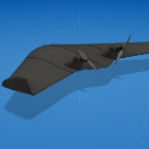
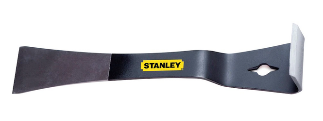
to separate the cover from the main body, you need to pry it from the inside from under the screw posts. if your print settings are just right, it pops off with moderate force. to do this, I placed the part in an open vice and pried with one of these:
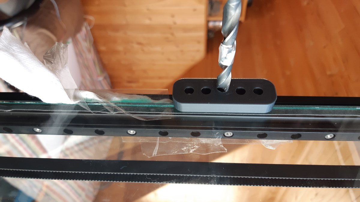
drill size is 9/32" or 7mm or 7.5mm max. drill at high speed and low pressure to prevent sudden biting, take breaks to prevent melting of the drill guide
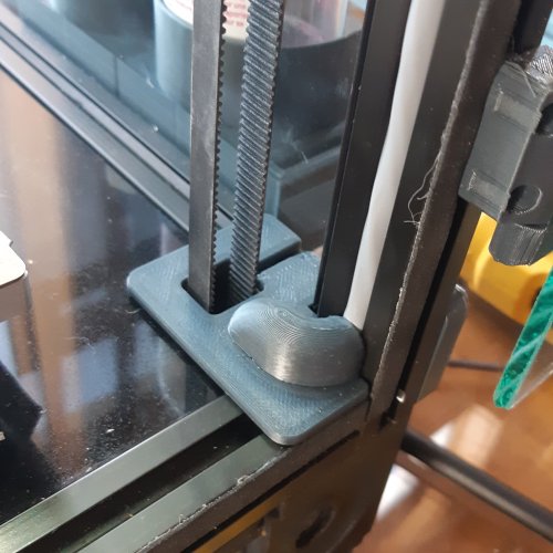
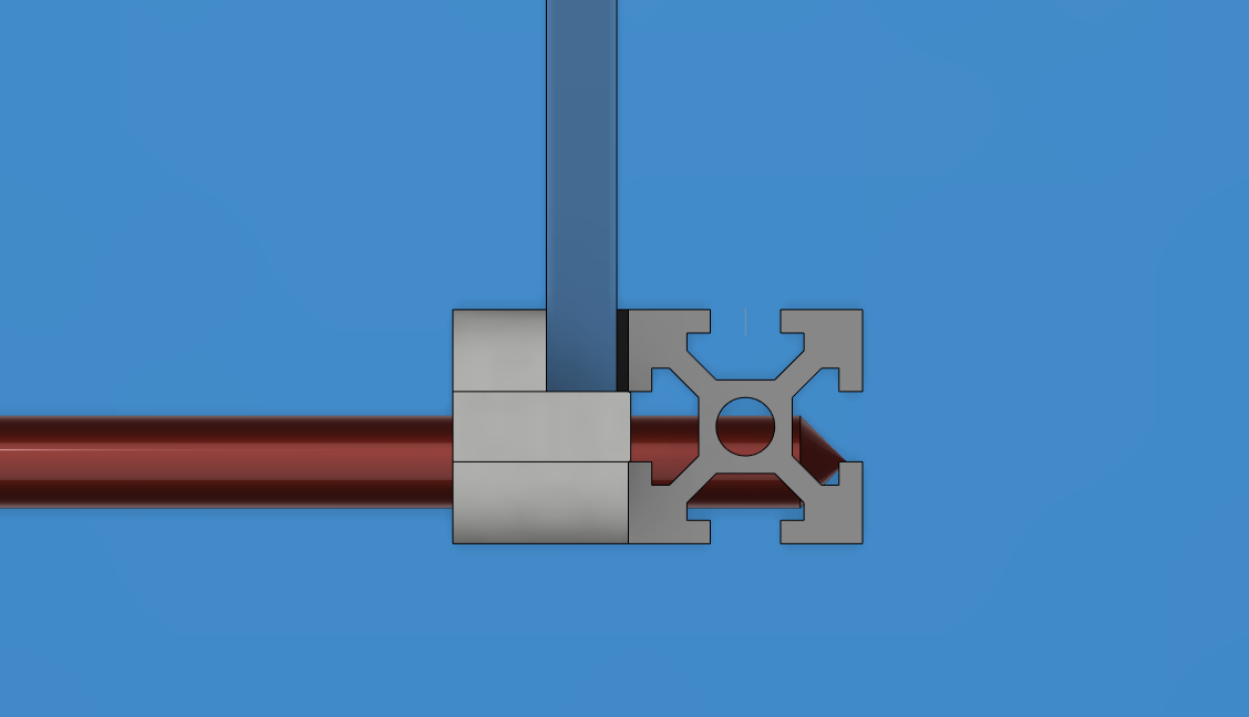
The cable I used is a leftover from industrial worksites. the passages are for a 7mm cable so anything smaller than that will work. you will need to splice usb cables somewhere in there so take care of adding shielding, especially where the cables pass near the z motors at the corner of the base
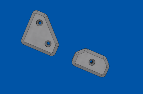
for the base: 2 x m3 t-nuts and 2 x m3-12 screws
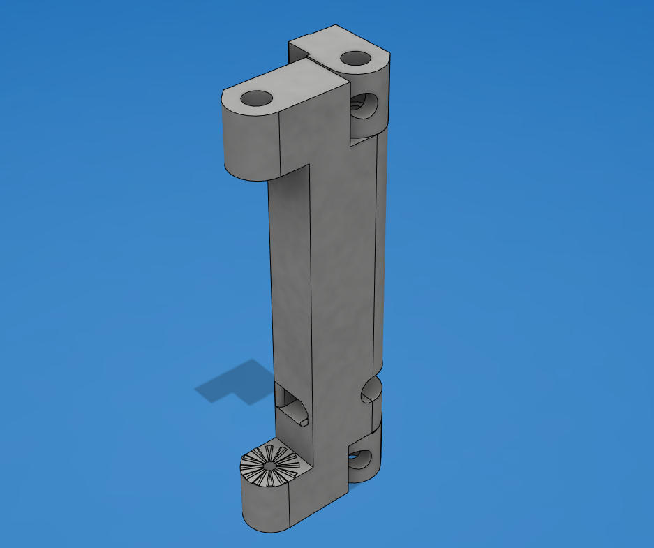
for the arm and main body joints, 2 x m3-30 and 2 x m3-12
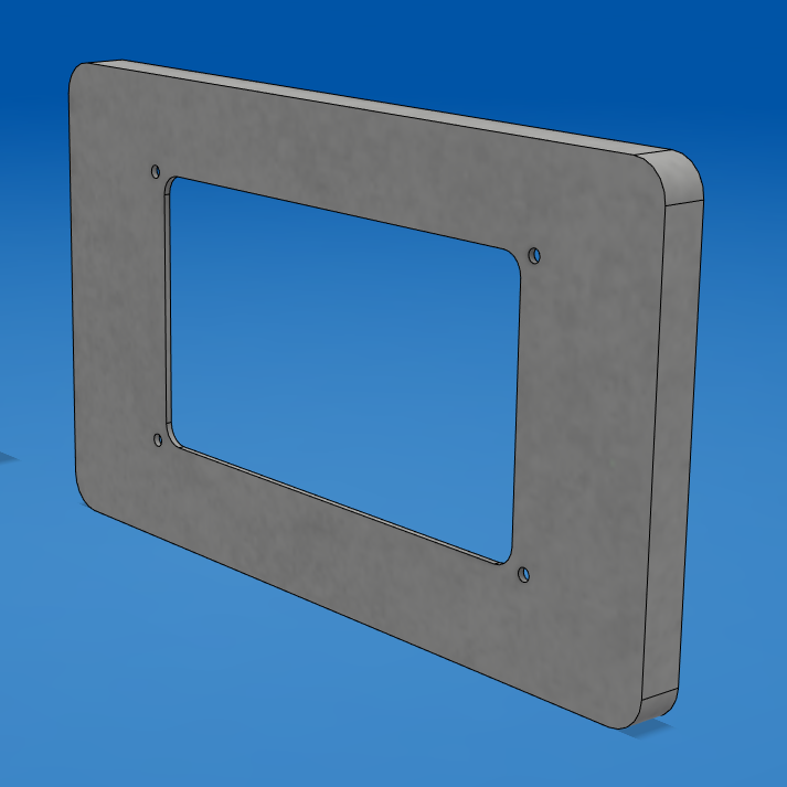
for the face: 4 x m3-8 and for the cover 2 x m3-12
also, the screen's included m2.5 brass posts are too long by almost 2mm and need to be replaced. -->testing needed but I got an assortment box:
https://www.amazon.ca/gp/product/B06XX28ZZR/ref=ppx_yo_dt_b_asin_title_o03_s00?ie=UTF8&psc=1
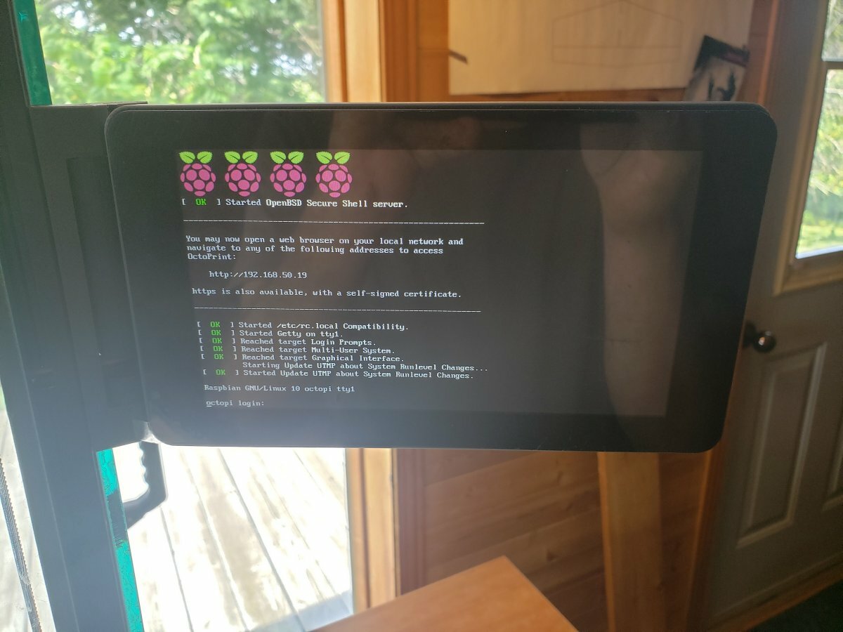
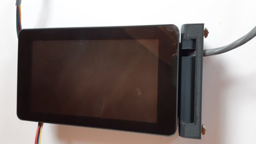
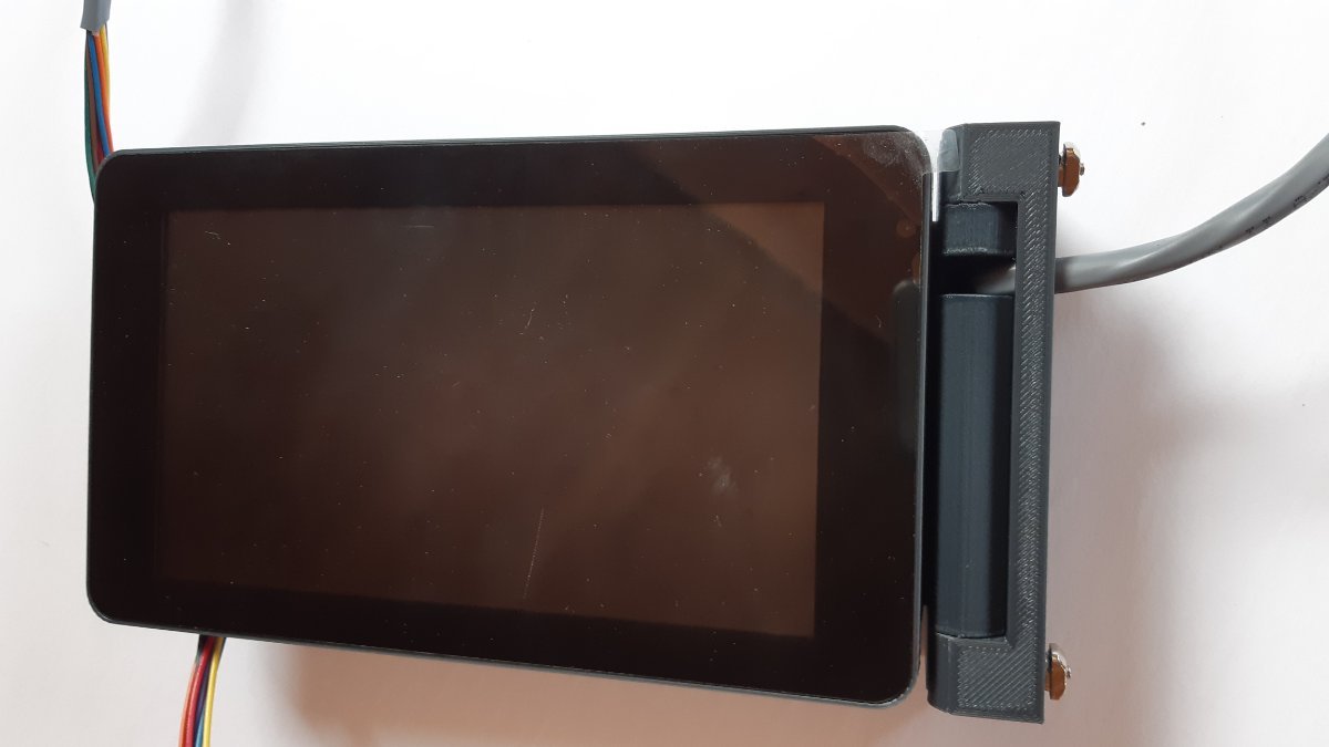
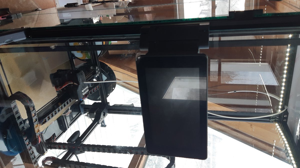
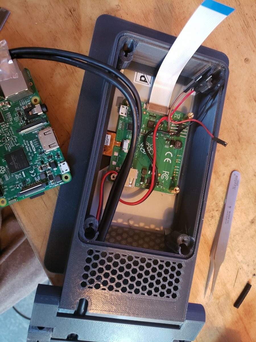
Finally got the time to get it working:
power management: I soldered on the monitor's PCB cause I had no space to plug on the header. I added 2 pairs of wires for the Pi and for the fan :
USB:
For cables, I just used 2 spare USB A-B cables from a dusty box. Try to get the thinnest possible wires that are shielded.
Here is a suitable choice for a spool of generic USB 2.0 shielded wire:
https://www.digikey.ca/en/products/detail/cnc-tech/2725-2828-BL-01000-A/6023708
Since the cable needed a splice in any case, I bought 'Type-A' USB connectors to make my own cable termination:
https://www.digikey.ca/en/products/detail/adam-tech/USB-AP-S-RA-SMT/9832307

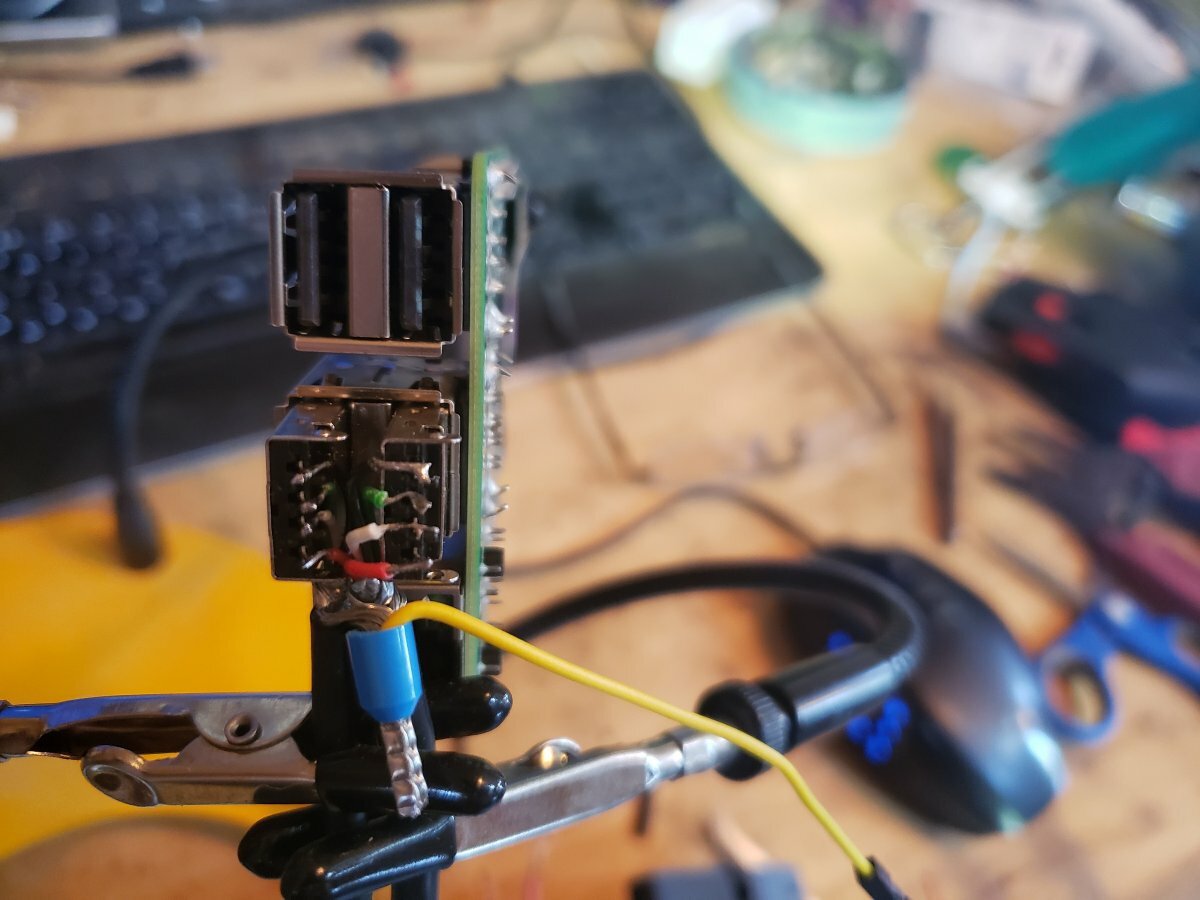
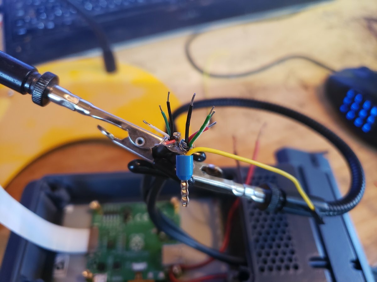
Keep the wires as short as possible. I used a ferrule to join up the sheathings from both cables, which includes stainless steel, aluminum, copper, cotton and mylar... It can't be soldered !
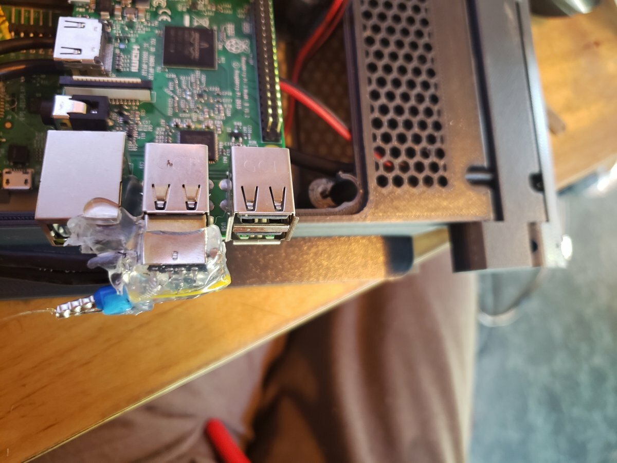
Hot-Snot for that extra Chineseum touch also, I soldered a solid copper rod between the two connectors for strength. you can see it through the snot on the right side
As for the other ends of the cables, I just did a simple soldered splice with heat shrink: made them as short as possible, as straight as possible, and I introduced 1 turn between the data lines in the joint and shielded with foil tape.
RF shielding and hot-snot hider: it's just aluminum foil tape:
All working! looks awesome!