Leaderboard


Popular Content
Showing content with the highest reputation since 06/09/2025 in all areas
-
Remember: these are glorified, computer-controlled hot glue guns. Off by a hundredth of a millimeter is fine. The gooey plastic will compensate.3 points
-
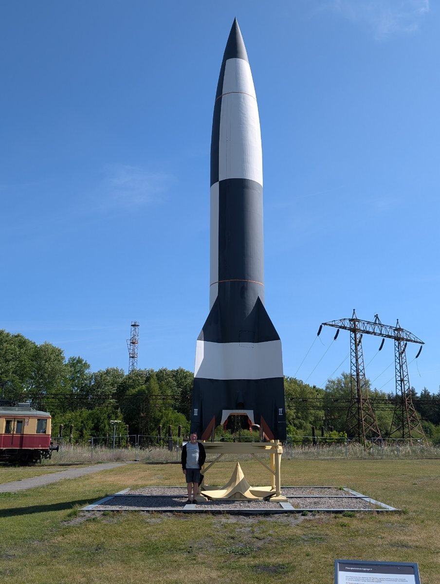
The other week I managed to get to the Technical Museum in Peenemunde to take a look at the V1 and V2s. Here's a link to a google photos folder with some more interesting items - https://photos.app.goo.gl/W1YHz6L7rruZuHEE7
 3 points
 -
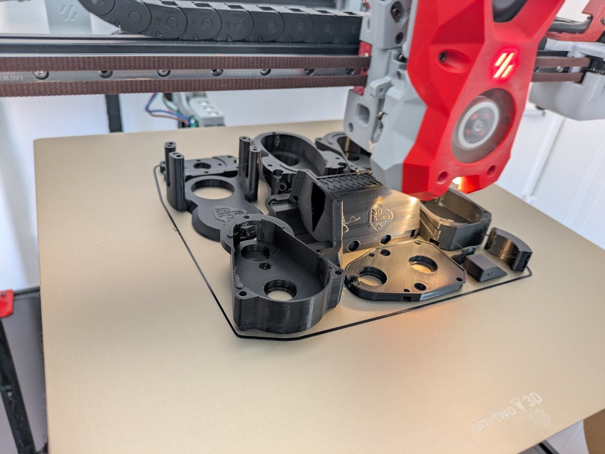
First chips on the Milo!!! First Chips.mp43 points
-
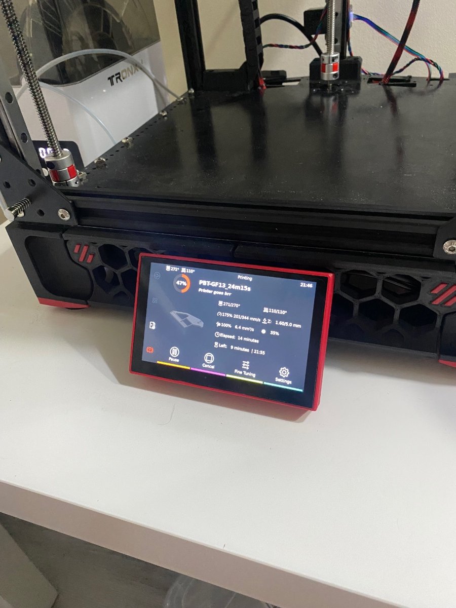
I’ve installed all stuff I posted before and btt hdmi5 screen and sfs 2.0 and… it’s printing!)
3 points
-
Version 1.0.0
21 downloads
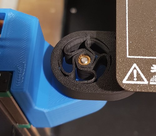
This mod replaces the GE5C spherical bearings used in a Voron Trident with printed flexures. After having issues with excessive vertical play while using low-cost spherical bearings, I developed these as a more reliable option. Each Z-carriage uses a Voron standard heat-set insert and an M3x16 BHCS installed from below. Before putting these flexures into service, I ran a 2 hour test cycling each Z-motor at 50mm/sec in a heated chamber (nearly 14,000 moves). This design is not suggested for use with the Voron TAP as the flexures introduce probing inaccuracies due to the force of the nozzle pressing on the print bed.2 points -
My VZBot 330 runs on an Octopus Pro board with 48V 5160 drivers. As a matter of fact all my printers are running Octopus boards. Have not had a problem on any. With the 5160 drivers it is important to note the wiring to the drivers as this is cause for the most issues I had. You will also need to connect the two power supplies via GND in order for the 5160 to operate. I am currently in the process of converting a Ender Plus to an AWD Mercury One with a 5 toolhead Lineux Toolchanger and this will run on an Octopus board with 48V 5160 drivers.2 points
-
Hi Kris. Just wanted to say thanks. Great service and customer accommodation. Definitely fast shipping. V2.4 kit LDO Milo 1.5 CNC + Casa
2 points
-
It's so good, im one for my Vz330.2 points
-
Thanks! Yes, I'm pretty pleased with the first cuts. Still need to learn more about the Cam setup. Learning by trial and error. Looking at ordering more end mills and still setting up "Air Blast" and MQL coolant.2 points
-
Oh yes! I forgot to mention that one it would be my first upgrade mod on a new printer.2 points
-
My V0 is almost complete. Next.. Milo 1.5 +Casa
2 points
-
Fridge door conversion was my best mod. Finally, a door that seals and keeps the fumes inside so the filter can take care of it. I print mostly ASA, so that is important. Second is converting my TAP to Dyze Horizon strain gage nozzle sensor. Way better than tap and 100% reliable and repeatable. I am currently working on an Orbiter3 conversion to enable reliable printing of TPU.2 points
-
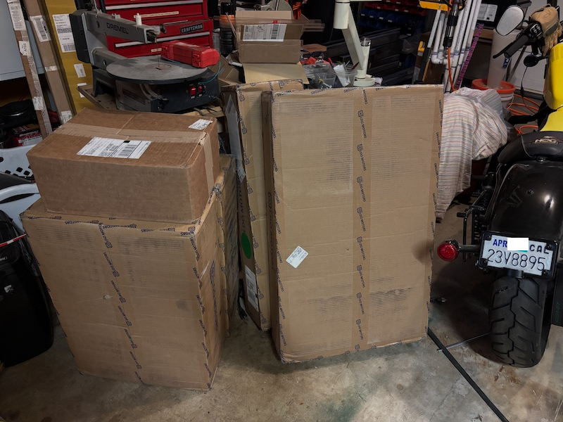
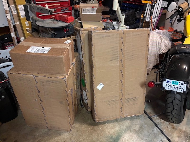
Trying something a little different with the trays:
2 points
-
Well the Box Turtle build has started. Colours for my 2.4 but it will start life on the test mule (Trident). Probably not worth a separate build log as there are a couple of good ones on here already. Build is 1/2 LDO and 1/2 Ali with a mix of ABS/ABS+ M600 filament change is great but is also a curse as it requires some babysitting - hopefully this solves the issue
2 points
-
Replacing TAP with E3D RevoPZ made the largest print quality difference so far. Replacing the BTT SB2209 with a Mellow SB2040 stopped an appetite for Hotend Thermistors.2 points
-
I second the Beacon probe, for sure, as a reliable first layer. I run sensorless homing on both my printers it works flawlessly when properly set up.2 points
-
Switching over to Beacon was a game changer for me. I also changed the extruder / hotend over to a Orbiter 2 and Rapido 2 UHF.2 points
-
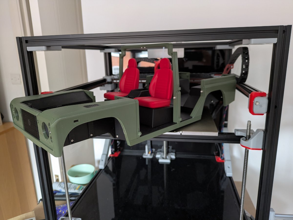
Update: 200 hours in and the Stealthburner certainly isn't a PLA queen but have managed to get through most of the PLA prints with reasonable results. All of the 3dsets Land Rover Wagon were printed and, i would say, 95% were very good. The other 5% are challenging and I am wondering if it is an issue with the toolhead or simply my tuning. I still have not finished it but life has been busy! I will get there .... Build now has a ACM back and lower panel but I have left the acrylic deck on there for now. Brace Brace Brace!! I added a couple of VZBot braces on the sides and used four of the trident Z axis stepper mounts in the top to keep the top square and braced the same as the bottom. I was thinking of popping 4 round LED's in the holes. They worked out very nicely! Running KlickyPCB for endstop and it has not had a fault in the 200 hours of printing so far - so much more reliable with first layers then my 2.4 using the z switch and klickyPCB separately. I have set up adaptive mesh and exclude object (so so easy! why didn't I do this earlier???) - this is native on Klipper now. Still have to clean up under deck but that is tabled for when I get a new toolhead and pass the StealthBurner back to the other machine. So what is next? Toolhead definitely. I am tossing between XOL or A4T-AFC with Galileo wristwatch or spunking up for a LDO Jabberwocky Toolhead & Extruder. This is, after all, going to be the test bed for a Box Turtle and possibly one other MMU/AFC - I want to build one for the 2.4 (simple two or 3 colour for ABS) and one for this .... or if I get one very cheap I could have a go at an ERCF V2. To be continued ......
2 points
-
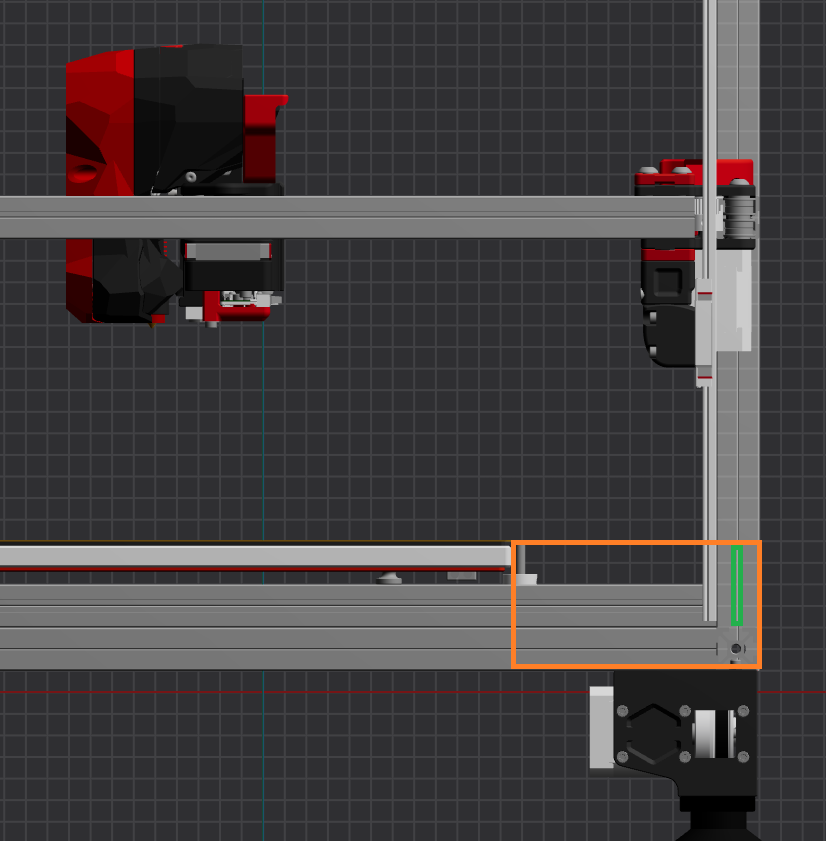
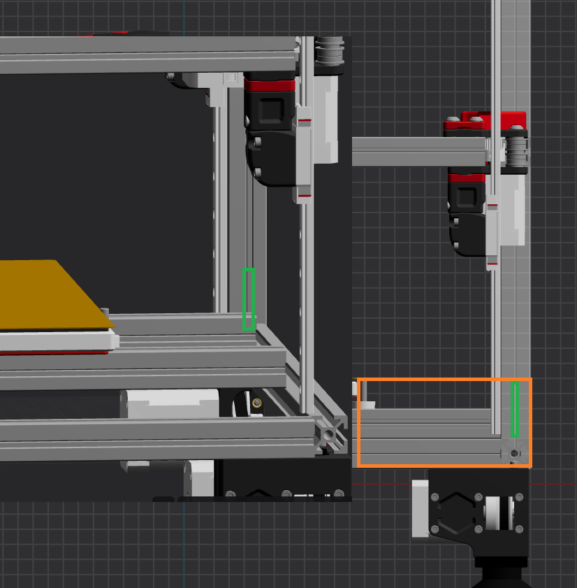
Hi, Your post was from a while ago, so I hope the moderators don’t mind me reviving it and read the reasoning for allowing this further ahead. But first, a little background: I was skimming through a video that’s over two years old when I noticed a strange .cfg file. A quick Google search—bada bing, bada boom—and here I am. I have no idea what was available a year ago, but it looks like the conversation back then was centered on the XY-axis. The consensus was (and still is) to just get the backers and forget about it, which honestly sounds fair and true even today. For 2025, as of my reply, the discussion seems to be focused on the Z-axis specifically. With a little digging, I found posts, commits, and development around this exact topic as recently as last month. This means the topic is fresh and ongoing. The question is about the Z-axis, specifically where to place the thermistor. I have exactly the same question. Based on the goal (measure vertical extrusion temperatures) and checking the [Z_Thermal_Adjust], it looks like just one (1) NTK 50K thermistor is used. I'm guessing one that's anywhere between 19 - 39 " so you can comfortably route it as needed. As for the placement... Now, In terms of redundancy: "Two is one, and one is none". Therefore, I'm incline to place 8 thermistors. Two on each vertical extrusion, one inside the vertical extrusion channel to directly measure the extrusion temperature and the other facing inwards like an antenna. At a glance, this looks like a great place for such a configuration: Hot air expands, and rises; cooled air contracts – gets denser – and sinks. I say this, because I don't have advance software and I have not done any math... but I'm guessing that the sensors being this high is going to cause some issues in regards with timing (turning heaters / blowers off)? I'm so tired. I shouldn't be writing now and sharing this preliminary info - but hey it's FOSS / RepRap. Take all I've written so far with a grain of salt and very very early info. I'm not diving into the second half of the post for now. I want to see if this peaks anyone's interest and what the feedback is. Cheers!
1 point
-
Thank you for this file and design , also see it as a great way to account for thermal expansion1 point
-
That's the one that caught me on my VZ330 AWD build.1 point
-
Monitor the fan noise ,if its gettng louder then replace ,your asking how long is a piece of string ? good fans will last ,cheap fans will not .1 point
-
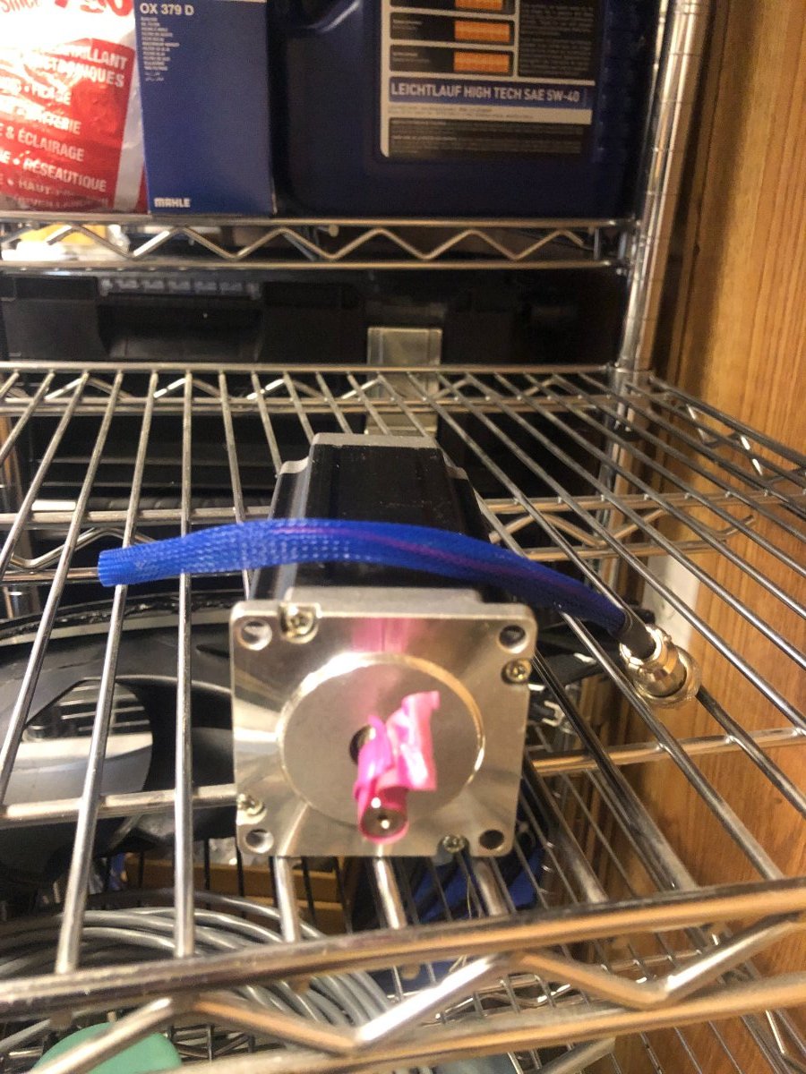
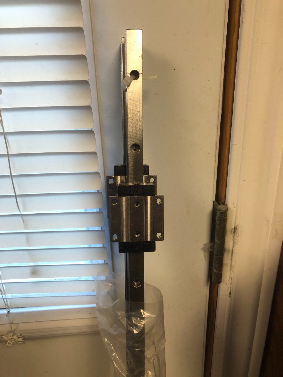
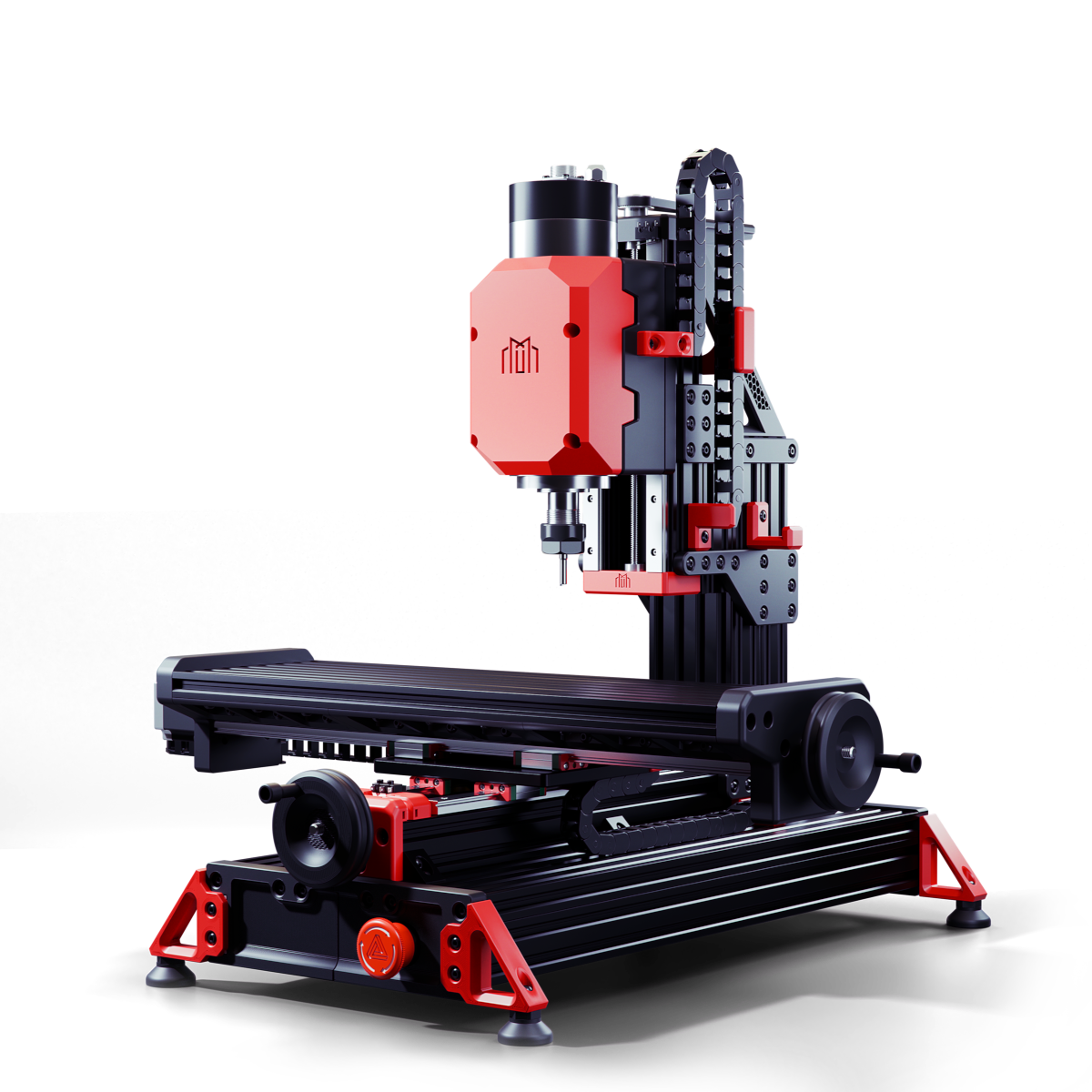
Milo V1.5 CNC Bench Mill Github Link Not a 3D printer but still going to be an interesting build The idea is to eventually make parts to replace the printed parts on the mill and for the Trident and V2. This is going to be a slow build, I'm self-sourcing the parts and will assemble them as parts are purchased and arrive. Years ago I purchased some parts to build a CNC machine but never completed the build. The frame and spindle were the last items to be purchased and built. Since then electronics for CNC have come a long way specifically the stepper drivers and motherboards. I already have the Nema 23 stepper motor but are larger than the suggested spec for the build. I'll be testing them with the Mellow 32bit FLY-CDY V3 Wifi Control Board when it arrives. These are the steppers I'll be testing: I have these Hiwin HGR 15 linear rails which I can cut to length, the blocks don't match the printed parts, but I can either modify the printed parts or order new blocks. The blocks alone will cost the same as purchasing a complete set of rails. The advantage of using Hiwin rails is the pre-load. Appreciate the lesson on the basic use of Fusion 360 that @Penatr8tor was kind enough to give me on Zoom. Parts ordered: Mellow Fly-CDY-V3 Complete Fastener Kit 2 x 4010 24V. Fans
1 point
-
It took some time for me to get my machine to a place where it would home and the axis to react correctly to code. PFARM gave me a lot of support as well as other sources out there so Kudos to them all. ( Thanks again guys )1 point
-
Same with both of my 2.4r2 Voron; 350 and 300 mm. The drop after power-off is almost invisible, but it definitely needs a QGL the next power-up. As mentioned before, the Startup script always runs a QGL and a Z calibration (not offset) before each print as the cabinet and the bed have warmed-up.1 point
-
Well done! Great job!1 point
-
Hi all, I've been running my Voron 2.4 for a few months now and overall, it's been fantastic. Solid performance, reliable prints, and the build process was actually fun. That said, I'm starting to look into mods and upgrades — not just for aesthetics, but for actual performance or maintenance improvements. I’m curious: What single mod or upgrade made the biggest impact on your Voron build? Was it the Klicky probe? Stealthburner? CANbus? A specific fan duct or printed part? Or maybe something more subtle like cable management or firmware tweaks? Whether it’s worth recommending to someone still relatively new to Voron Would love to hear your experiences and maybe get inspired for my next upgrade path! Thanks in advance!1 point
-
Looks awesome! Thank you!1 point
-
Printed parts are found here. Measure the side-to-side and top-to-bottom extrusion and cut accordingly, or there are Clicky Clank door kits out there.1 point
-
Carbon fiber gantry, sensor-less homing, cartographer touch and 520mm build height and a glass bead. The biggest, best mod was the orbiter V3 revo as the prints are perfect and I can print nearly every filament form PLA to PC and even nylon. That and I can change nozzles with one hand. I am so glad I found the Voron and the communities that support it. Can set up with the help of Esoterica's write up was bullet proof. The baud rate of the early EB36 was a problem, so I went with Duet. The Duet CAN worked but their scanning Z probe is surface mount and problematic. I went back to a Manta M8P as the EBB was now 1M baud rate. The Manta has an integrated CM4 with EMMC memory running Kipper and mainsail with a cartographer 3d probe. The Mellow Fly SHT36 would drop the UUID for Fly sht36 plus when the can was plugged into the fly or spliced at the motherboard. The EBB36 works as well as Duet but and the cartographer scanning probe is a better design. That and they both (EBB, Carto) have input shaping which also helps print quality.1 point
-
Yep fully normal. My Z axis sags enough that it needs to be recalibrated on every print. Yet another reason why, IMO, the Trident is a better design than the 2.4.1 point
-
Congrats Jack! Awesome to see chips fly and it looks and sounds really solid.1 point
-
CNC-Tap V2, CAN-Bus, Custom Toolhead/CPAP system for more cooling and lighter system (beta version is almost done!).1 point
-
Mine always does 2 "laps" when I QGL it. But, mine does not sag when I turn it off (which I hardly ever do). It shouldn't sag on power-off, the belt gearing is suppose to prevent sag. Check the Z belt tension.1 point
-
The gantry leveling procedure will run every time you start a new print job. At least, it should. Make sure the gantry leveling procedure is called out in your startup file. Yes, the gantry can sag and go out of level when the stepper motors no longer lock it in place when the machine is turned off.1 point
-
Yeah, you bet it's been over a year, self-sourcing slowed progress, and the last bit was finding bellows for the Y axis. With this first process found some things that need to be tweaked. Need to move the toolsetter to the opposite side where I first had it to prevent the touch probe from getting tangled in it during probing.1 point
-
Tap and Galileo2 for me. I went from stock inductive probe to Klicky which was an improvement. But Klicky was always fiddly. Tap was a little bit of a challenge initially (I also started with the beta, so extra challenges). But once set up, it's been great. Galileo2 is a simple build and has been dead reliable since I switched. Clockwork isn't bad, but Galileo is easier to run. I even switched my V0.2 over to the stand-alone version.1 point
-
Woohoo! It's been a long road to get to that little video.1 point
-
I forgot about sensorless! It takes a bit of fettling to get it working correctly. But once its set up it works, and if it starts homing before hitting end stop - it's time to inspect the rails and moving parts. Don't try it on a 330 AWD, it doesn't play well with mote than one motor on the same axis.1 point
-
A quick update. All is well and the Vz is running smoothly, and with a 0.8mm nozzle it fair lays down some plastic. I just have to develop a better mount for the SHT36 and install the RSCS. I tried printing a Temp Tower in PLA, the 0.8mm nozzle puts out some much filament that the CPAP cannot cool it quick enough. I get back on it when I return from Italy in 2 weeks.1 point
-
There are a few mods on the printer from some very generous people. I will slowly add them to this page as there really is some top talent giving their time to the community!1 point
-
Yeah that pretty much confirms my own feelings on it, Nikos. Actually, though, when I turn off my TV... it's not really OFF, as in unplugged from wall off. It's in a standby state, so it's still energized. Got a few other devices around here that are the same way; it amounts to a continual 'parasitic draw' on the house current. Negligible in terms of absolute amount, but with these things, off isn't really OFF. With something like a printer, I'd prefer it be OFF when I'm done, as it's a potential fire hazard - - I wouldn't leave my countertop toaster-oven on unattended either. It just *feels* safer, even if it does introduce more 'wear and tear' on the electronic components. They're cheap enough. Yah, *anything* that makes heat draws a ferocious amount of current. I haven't gone with UPSs, as if you want to run electronics you really need a true sine-wave UPS, not chopped DC, and true sine are a lot spendier than their 'chopper' cousins! Power around here's pretty reliable, Winter and big storms with high winds being what usually takes it out.1 point
-
Okay. So I cleared those warnings, and homed, they did not come up again.1 point
-
Okay that fixed it.. My bad..1 point
-
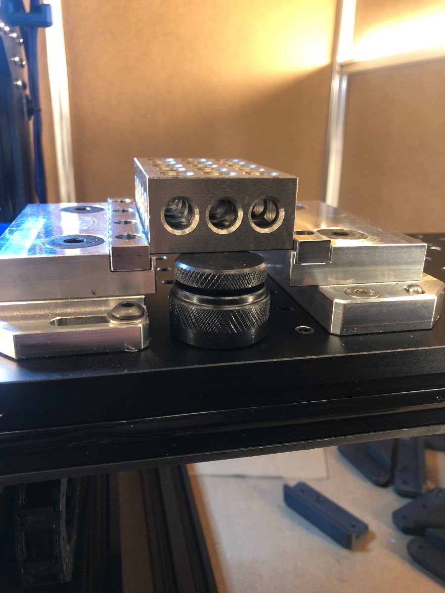
I purchased two of these machinist jacks, used to support overhangs of 1 inch or greater to prevent chattering. The second one to arrive tomorrow. Adjusts from 23mm to 30mm. These work nicely with the Saunders Metal Works hobby vice. Machinist Jack Link
1 point
-
Thanks for the info. Must be a lot of people like them, because there are none for sale on eBay. Lots of used POS Enders; I've been down that route !! Would love to have a Voron, but don't have the time or inclination to build one LOL1 point
-
One of my friends had almost this exact same issue. They were using a high quality SD card and had nothing wrong with their raspberry pi. The problem ended up being from them hard shutting down the raspberry pi by just flipping the power switch on the printer whenever they wanted to turn the printer off. Once they started properly shutting down the raspberry pi before flipping the power switch the problem went away. That was the first time I had actually seen a raspberry pi have file corruption from hard shutdown even though I knew it was possible. The reason I was able to determine that this was the most likely cause was that several of the log files had a corrupted line in them right at the time the printer was last turned off. I used Visual Studio Code to look at the log files, it shows corrupted lines with a red bar that says "NULL" over and over.1 point
-
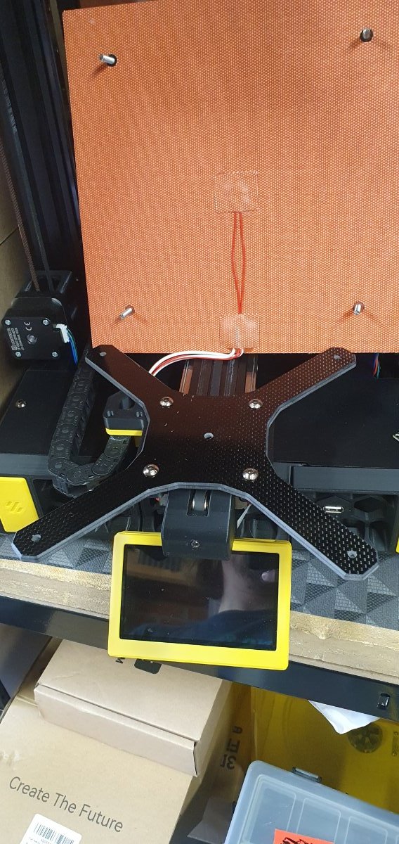
I cut a carbon fiber y carriage today, its 114g :), about 132 grams lighter than my old cut down ender axis. I also released I had some little paper washers under the bed spacers, took the two out from the front and the range has reduced from about 1.1mm to 0.3 :).... Happy with that.
1 point
-
Version 1.0.0
129 downloads
Makes it possible to use a UM2 lock to hold your Bowden Tube in place, often it can let go when loading your filament manually, this fixes that.1 point -
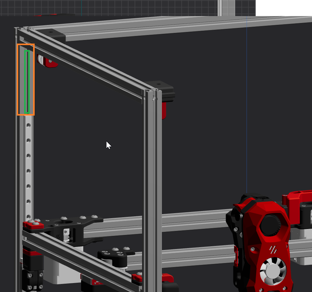
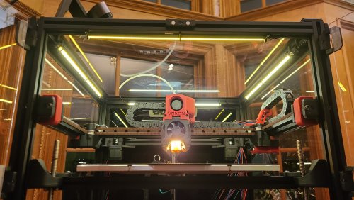
Version 1.0.0
318 downloads
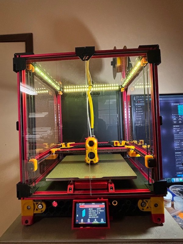
SuperSlim LED This is a design I'm calling the SuperSlim. It's a super slim LED bar that fits at a 45 degree angle on the 2020 extrusion at the top of your Voron. You print out these small and simple brackets, clip them onto the LED bar and against the extrusion, and presto! You have a gorgeous looking, bright, and simple LED light. Even better these bars use micro LEDs so you get a lot of light diffusion, i.e. no hot spots, and one of the best final looking lights out there for your Voron. SuperSlim Bracket The bracket truly makes this design awesome and simple. Here it is in all its simple glory. Print 12 of these. In fact print 20 of these and use them to push/hide your wires tucked into the extrusion slots as well because they're so quick to print, easy to snap in, flexible, strong, sexy looking, and durable. And they're fun to print on your new ABS capable Voron. Grab the STL or 3MF file attached to this post to print out the bracket using your favorite slicer. Use 0.3mm layer height for faster prints that are stronger. Use 4 walls to achieve basically no infill. 100mm/s speed should be fine. Micro LED Bar Here's a link for the LED light bar on Aliexpress. There are several vendors, so just search 300x6mm LED. Get the Warm White color temperature. Too stark of a bright white is harsh to look at. 300x6mm LED Lights (Pack of 10. About $1.70 each.) https://www.aliexpress.com/item/32786326547.html Wiring / Soldering The light bars are 12V, so to plug them directly into your control board's 24V output, like HE2 (heater 2), so you can control the light from Klipper, you need to wire up 2 of the lights in serial to get 24V. Then wire up the other 2 in serial for another 24V. Then connect those together in parallel to drive off of one heater output. So connect the + out of HE2 to the + on your first LED bar (LED1). Then connect the - from LED1 to the + on the your 2nd LED bar (LED2). Then connect the - on LED2 to the - on HE2. Go ahead and test out LED1 and LED2 by turning on HE2 using the settings in the section below. Once you're happy, go ahead and finish connecting the last 2 LED bars the same way you did this set of LED bars in step 1 thru 3. Configuring Klipper You can see it here in Mainsail called "Caselight". Here is the printer.cfg settings for controlling the LEDs. [output_pin caselight] # Chamber Lighting - HE3 Connector (Optional) pin: PB11 pwm:true shutdown_value: 0 value:0.06 cycle_time: 0.0002 # with 0.0002 the min is 5%. 7% seems like a good idle state. 40% for prints. over 60% to 100% all seems to be same brightness # with 0.0001 the min is 9%. 12% seems like a good idle state. over 60% to 100% all seems to be same brightness hardware_pwm: True Add some macros as well for convenience. [gcode_macro LED_ON] gcode: SET_PIN PIN=caselight VALUE=1 [gcode_macro LED_PCT_IDLE] gcode: SET_PIN PIN=caselight VALUE=0.06 [gcode_macro LED_PCT_PRINT] gcode: SET_PIN PIN=caselight VALUE=0.4 [gcode_macro LED_OFF] gcode: SET_PIN PIN=caselight VALUE=0 Then modify your Start / End / Cancel macros so they turn up and down the lights when you start or end your print. The Start macro... [gcode_macro PRINT_START] # Use PRINT_START for the slicer starting script - PLEASE CUSTOMISE THE SCRIPT gcode: ;SET_PIN PIN=caselight VALUE=0.4 ; turn on case light LED_PCT_PRINT The End macro... [gcode_macro PRINT_END] # Use PRINT_END for the slicer ending script - please customise for your slicer of choice gcode: LED_PCT_IDLE The Cancel macro... [gcode_macro CANCEL_PRINT] description: Cancel the actual running print rename_existing: CANCEL_PRINT_BASE variable_park: True gcode: LED_PCT_IDLE You should end up with some nice macros that turn your lights on and off at the right time. This video walkthrough of my serial request will help you get an idea of what these lights look like in a video.1 point