Leaderboard
-
in Files
- All areas
- Blog Entries
- Blog Comments
- Links
- Links Comments
- Links Reviews
- Tutorials
- Tutorial Comments
- Tutorials Reviews
- Support Replies
- Comments
- Files
- File Comments
- File Reviews
- Images
- Image Comments
- Image Reviews
- Albums
- Album Comments
- Album Reviews
- Topics
- Posts
- Records
- Record Comments
- Record Reviews
- Status Updates
- Status Replies
-
Week
-
All time
August 27 2021 - June 16 2025
-
Year
June 16 2024 - June 16 2025
-
Month
May 16 2025 - June 16 2025
-
Week
June 9 2025 - June 16 2025
-
Today
June 16 2025
- Custom Date
-
All time
Popular Content
Showing content with the highest reputation since 06/09/2025 in Files
-
Version 1.0.0
21 downloads
This mod replaces the GE5C spherical bearings used in a Voron Trident with printed flexures. After having issues with excessive vertical play while using low-cost spherical bearings, I developed these as a more reliable option. Each Z-carriage uses a Voron standard heat-set insert and an M3x16 BHCS installed from below. Before putting these flexures into service, I ran a 2 hour test cycling each Z-motor at 50mm/sec in a heated chamber (nearly 14,000 moves). This design is not suggested for use with the Voron TAP as the flexures introduce probing inaccuracies due to the force of the nozzle pressing on the print bed.2 points -
Version 1.0.0
6,194 downloads
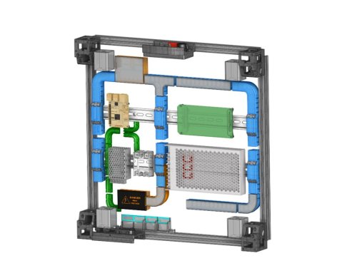
This Remix of RyanDam's Cable Management Duct for Voron Printers includes a number of custom ducts which I am using in my Voron 2.4 build. Thanks to the original author for the excellent design of the ducts, which this remix is based on! Since these models are designed to work with electrical components, if you use these models, it is at your own risk. Included here are several customized ducts which may help with cable management in a Voron build. I am still in the process of building mine, and I chose to use the same electronics layout as the voron spec. These ducts were designed based on my FYSETC R2.4 kit (which I am building as an R2.4 V2), so some dimensions may be different in other kits. This was designed with help from the STEP file from the Voron Github. There are several ducts included, which are designed to go over the DIN rails, and these parts include “BRIDGE” in their names. These parts will need to be printed with supports. There is an integrated support in the “HALF_BRIDGE” part, but that could also be printed with supports if needed. The “HALF_BRIDGE” part also has a thin raft like integrated support which will need to be removed. The 90 degree full bridge ducts are slightly different between the right hand (RH) and left hand (LH) versions. The difference is that the RH version (Cable_Management_Duct_Remix_DUCT-FULL-BRIDGE_90DEG_RH_5B.stl) is cut off a bit short to allow the power supply stabilization bracket to pass. I set my ducts up so that the high voltage AC wires, and the low voltage DC wires, would stay in separate ducts. To do this, I used two half ducts (one for the AC, and one for DC), on the center duct which crosses the lower DIN rail in the pics, which is nearest the power supply. I also printed the AC ducts in orange so they would be distinctive as a reminder they contain the high voltage AC wires. There are also plain and logo versions of the covers. The covers for the “BRIDGE” parts have print in place hinges, so if you find they are welded together when printed, it will be helpful to calibrate flow and horizontal expansion, as well as adjust the temps for the filament used. I made some minor improvements to parts since I printed mine (either for length or printability), but I do not think there will be any issues due to the changes. I printed the ducts for my printer in ABS and PETG, but use your best judgement on the appropriate material to use. I used VHB tape to secure them, but just note that once placed, they won't likely be going anywhere soon. Parts are not oriented for printing. Feedback is welcome, and if there is a problem I will try to fix it as I have time. I'm still building my printer, so if I run into an issue with this design, I will update it further, however I don't foresee any interference issues currently. Most likely I will not be able to accommodate requests to customize these further. The STEP files can be found on Printables (since the file was too large for this site), so remixing will be simpler. If you print these, or use these, it is at your own risk. I posted some remix covers for the boxes, which have inset printed labels, as well as some single and double wire guides which I am using to secure my ground wires. If you find these models useful, please post a like or a comment with some pics of your prints. You can find some other things I am working on at my blog (https://www.mystoopidstuff.com/blog), thanks for looking! You can find some additional low profile wire guides here: https://www.printables.com/model/502345-wire-management-guides There is a remix of the small box (not included here but shown in the pics), which holds two WAGO 221-415 connectors here: https://www.printables.com/model/505826-wago-box-for-the-remix-of-ryandams-cable-managemen The AC caution covers, with inset text and warning symbols for the small box and half bridge duct, can can be found here: https://www.printables.com/model/505838-ac-caution-covers-for-remix-of-ryandams-cable-mana/files1 point -
1 point
-
Version 1.0.0
322 downloads
SuperSlim LED This is a design I'm calling the SuperSlim. It's a super slim LED bar that fits at a 45 degree angle on the 2020 extrusion at the top of your Voron. You print out these small and simple brackets, clip them onto the LED bar and against the extrusion, and presto! You have a gorgeous looking, bright, and simple LED light. Even better these bars use micro LEDs so you get a lot of light diffusion, i.e. no hot spots, and one of the best final looking lights out there for your Voron. SuperSlim Bracket The bracket truly makes this design awesome and simple. Here it is in all its simple glory. Print 12 of these. In fact print 20 of these and use them to push/hide your wires tucked into the extrusion slots as well because they're so quick to print, easy to snap in, flexible, strong, sexy looking, and durable. And they're fun to print on your new ABS capable Voron. Grab the STL or 3MF file attached to this post to print out the bracket using your favorite slicer. Use 0.3mm layer height for faster prints that are stronger. Use 4 walls to achieve basically no infill. 100mm/s speed should be fine. Micro LED Bar Here's a link for the LED light bar on Aliexpress. There are several vendors, so just search 300x6mm LED. Get the Warm White color temperature. Too stark of a bright white is harsh to look at. 300x6mm LED Lights (Pack of 10. About $1.70 each.) https://www.aliexpress.com/item/32786326547.html Wiring / Soldering The light bars are 12V, so to plug them directly into your control board's 24V output, like HE2 (heater 2), so you can control the light from Klipper, you need to wire up 2 of the lights in serial to get 24V. Then wire up the other 2 in serial for another 24V. Then connect those together in parallel to drive off of one heater output. So connect the + out of HE2 to the + on your first LED bar (LED1). Then connect the - from LED1 to the + on the your 2nd LED bar (LED2). Then connect the - on LED2 to the - on HE2. Go ahead and test out LED1 and LED2 by turning on HE2 using the settings in the section below. Once you're happy, go ahead and finish connecting the last 2 LED bars the same way you did this set of LED bars in step 1 thru 3. Configuring Klipper You can see it here in Mainsail called "Caselight". Here is the printer.cfg settings for controlling the LEDs. [output_pin caselight] # Chamber Lighting - HE3 Connector (Optional) pin: PB11 pwm:true shutdown_value: 0 value:0.06 cycle_time: 0.0002 # with 0.0002 the min is 5%. 7% seems like a good idle state. 40% for prints. over 60% to 100% all seems to be same brightness # with 0.0001 the min is 9%. 12% seems like a good idle state. over 60% to 100% all seems to be same brightness hardware_pwm: True Add some macros as well for convenience. [gcode_macro LED_ON] gcode: SET_PIN PIN=caselight VALUE=1 [gcode_macro LED_PCT_IDLE] gcode: SET_PIN PIN=caselight VALUE=0.06 [gcode_macro LED_PCT_PRINT] gcode: SET_PIN PIN=caselight VALUE=0.4 [gcode_macro LED_OFF] gcode: SET_PIN PIN=caselight VALUE=0 Then modify your Start / End / Cancel macros so they turn up and down the lights when you start or end your print. The Start macro... [gcode_macro PRINT_START] # Use PRINT_START for the slicer starting script - PLEASE CUSTOMISE THE SCRIPT gcode: ;SET_PIN PIN=caselight VALUE=0.4 ; turn on case light LED_PCT_PRINT The End macro... [gcode_macro PRINT_END] # Use PRINT_END for the slicer ending script - please customise for your slicer of choice gcode: LED_PCT_IDLE The Cancel macro... [gcode_macro CANCEL_PRINT] description: Cancel the actual running print rename_existing: CANCEL_PRINT_BASE variable_park: True gcode: LED_PCT_IDLE You should end up with some nice macros that turn your lights on and off at the right time. This video walkthrough of my serial request will help you get an idea of what these lights look like in a video.1 point