Leaderboard


Popular Content
Showing content with the highest reputation since 08/27/2021 in Posts
-
I found this Canbus with CanBoot and Octopus excellent guide on Facebook, posted by TJ M. Wanted to share it with the community and make it easier to find! How to Use CAN Toolhead Boards Connected Directly to Octopus / Octopus Pro on CanBoot Klipper has a new CAN bus feature, the USB to CAN bus bridge communication for Octopus boards (and other compatible MCUs). This feature allows the Octopus boards (and other compatible MCUs) to act as a USB to CAN bus adapter. This replaces the need for an adapter like a Raspberry Pi CAN HAT, canable adapter, or the Bigtreetech U2C board. What is CanBoot? CanBoot is a custom bootloader loaded onto your Octopus and EBB board that allows users to update Klipper firmware over USB, UART, or CAN comms without physically having to access the board reset buttons or BOOT jumpers. It uses the same ‘make menuconfig’ setup to configure and compile firmware. CanBoot is NOT required to use the Klipper USB to CAN bus bridge comms. But I have not tested this comms feature separately. You Will Need the Following USB-A to USB-C cable Power supply for Octopus and EBB toolboard (i.e. printer) RJ11 or RJ12 telephone cable, crimped to connect EBB board to Octopus See wiring info at end of guide. Best to setup wiring before installing software. Raspberry Pi, or similar, with Klipper / Moonraker / UI installed and working Computer with following software: SSH terminal software, I use PuTTY or Windows CMD WinSCP, to transfer files between Raspberry Pi and computer I also use Windows CMD to do this STM32CubeProgrammer Download for your computer OS and install https://www.st.com/en/development-tools/stm32cubeprog.html#getsoftware High Level Instructions, for Understanding Install CanBoot on Raspberry Pi, flash firmware to boards Configure and compile CanBoot firmware for Octopus / Pro and EBB Flash CanBoot to boards using STM32CubeProgrammer and computer Setup boards for Klipper Octopus - Setup Klipper for USB to CAN bus bridge, with CAN comms to EBB EBB - Setup Klipper for CAN comms Find serial device for Octopus / Pro on Raspberry Pi Flash Klipper to Octopus / Pro with CanBoot serial command Setup can0 network on Raspberry Pi, power cycle printer Find CAN uuid for Boards a. Connect EBB to Octopus / Pro, power cycle printer Flash Klipper to EBB board with CanBoot CAN command Printer Config Update and General Tips How to Use CanBoot to update boards, Tips Okay, enough talking! Let’s get started! (download the FULL 25 Page guide below! How to Use CAN Toolhead Boards Connected Directly to Octopus.pdf
 14 points
 -
Here is a fix for those that updated, that I copied from the discord chanel: "Shiftingtech V2.011 — Today at 4:03 AM A bug has been introduced in Debian Bullseye (which includes current MainsailOS), which prevents the symlinks in /dev/serial/by-id/ from being created. If your printer can't connect to the MCU anymore after a system update, you can check if it is caused by that bug by checking the installed version of udev with apt show udev If your version is 247.3-7+deb11u2 you have the broken package installed and should replace it with the "backports" version. Take special care about the last number ("u2"). 1. Install a working version from debian backports To install the working version of 252.5-2~bpo11+1 (one line, use copy & paste): cd ~;wget http://ftp.us.debian.org/debian/pool/main/s/systemd/libudev1_252.5-2~bpo11+1_`dpkg --print-architecture`.deb http://ftp.us.debian.org/debian/pool/main/s/systemd/udev_252.5-2~bpo11+1_`dpkg --print-architecture`.deb;APT_LISTCHANGES_FRONTEND=none sudo apt install --fix-broken ./libudev1_252.5-2~bpo11+1_`dpkg --print-architecture`.deb ./udev_252.5-2~bpo11+1_`dpkg --print-architecture`.deb; rm libudev1_252.5-2~bpo11+1_`dpkg --print-architecture`.deb udev_252.5-2~bpo11+1_`dpkg --print-architecture`.deb This command should just want to install the two packages (udev & libudev). If it tries to do something else, particularly removing a large quantity of packages, stop and reassess the situation 2. Reboot After doing that reboot the pi by running sudo reboot and Klipper should connect again to your MCU."13 points
-
So, this is something I want to try. The Orca Slicer team is working on a feature called Scarf Seams that aims to eliminate seams by creating a scarf like joint. It's still pretty early in the development cycle but looks really promising so far. Teaching Tech did a really nice video outlining the details...10 points
-
I have created a Mini Stealth v2 GitHub repository with 463 new .stl files in total. All of the different versions are organized into separate sub-folders in an attempt to make it easier to find the needed files. I am still working on the configurator and would be glad to accept help from anyone savvy with JavaScript. I will continue to be active here for support and feedback. I will maintain the v1.2.5 files here for archival and support as well. The new version parts are not compatible with the v1.2.5 parts but will still fit all of the older x-carriages. Below is a list of some of the main changes: More extruders have been added. More hotends have been added. The shroud is now separate from the core. The shroud fits onto the core with a pair of sliding grooves and can fit magnets to improve the connection if needed. The hotend can be installed to the core and then mounted to the printers' gantry. Everything else can be installed (or removed) while on the printer. All core pieces and shrouds are compatible with 25mm or 26mm x-carriages. :: i.e. Mini Stealthburner CNC aluminum carriages. All x-carriages are compatible with any hotend/extruder combination. There are specific UHF x-frames for Trident, V2.4 and Switchwire printers to provide probe compatibility. The V0.1/V0.2 x-carriages are much stiffer with side ribs that require included XY_Joint_Upper pieces. The 25mm spacing improves the Ender 3 mount which is available in the repo. The LED diffuser and carriage are new and simplified. The Rainbow BARF carriage is now in two part and should be easier to fit. All shrouds have standard, ZeroClick and Differential IR options. The 4010 blowers use a glued in (CA glue) air guide to increase airflow at the nozzle. The UHF shrouds have been re-worked to put the 4010 blowers lower, matching the standard shrouds. New probe mounting side brackets have been added that fit the Differential IR shrouds. Thanks to @Titus A Duxass for the concept! Biqu MicroProbe PINDA BL-Touch I have added Knomi2 shrouds that should also fit the Mellow Fly-Halo display. I have made Crop-Top shrouds for each extruder option. Each extruder has motor_bridge pieces that support cable management, cable chain mounts or umbilical PCB mounting. The umbilical PCB mounts are vertical for better ADXL readings. All parts have been modified for cleaner and more consistent geometry across versions. I will be on vacation next week but when I get back I will try to answer any and all questions here or on the comment pages for each extruder group. Happy Printing!!
9 points
-
Ahhhh the old angry mob strikes again. I once made the mistake of posting that I was using a Diamondback nozzle and cheap nozzle mob came after me. I barely escaped with my life.9 points
-
Yuo calling me girly? I'm just in touch with my feminine side
9 points
-
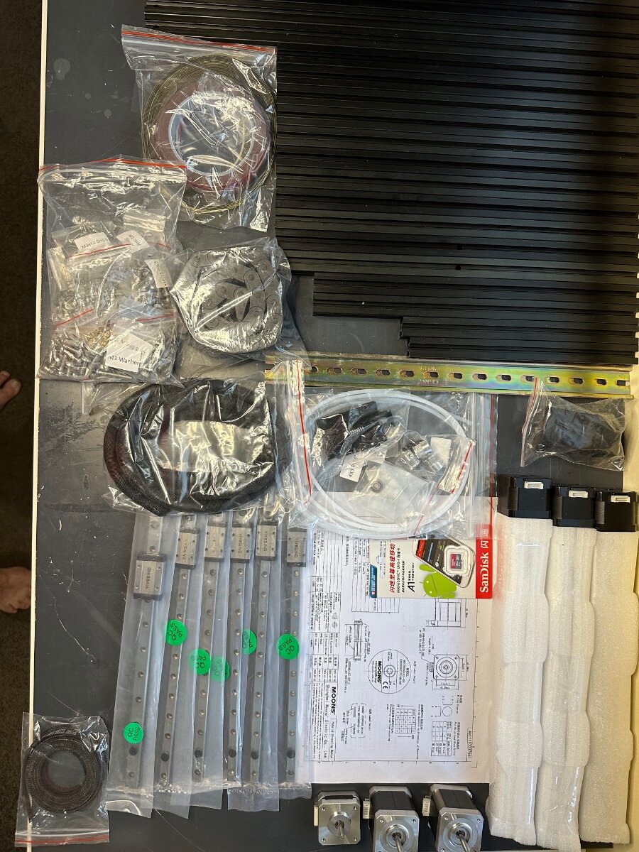
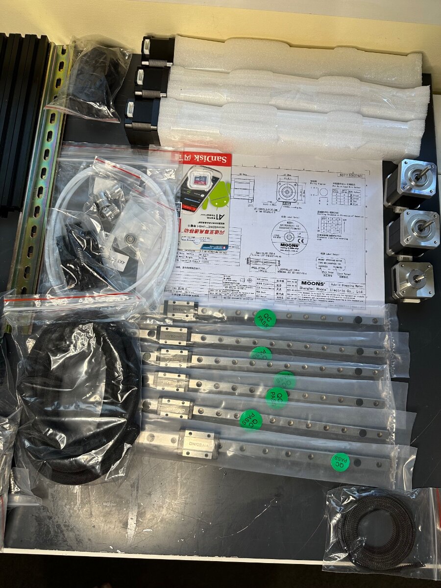
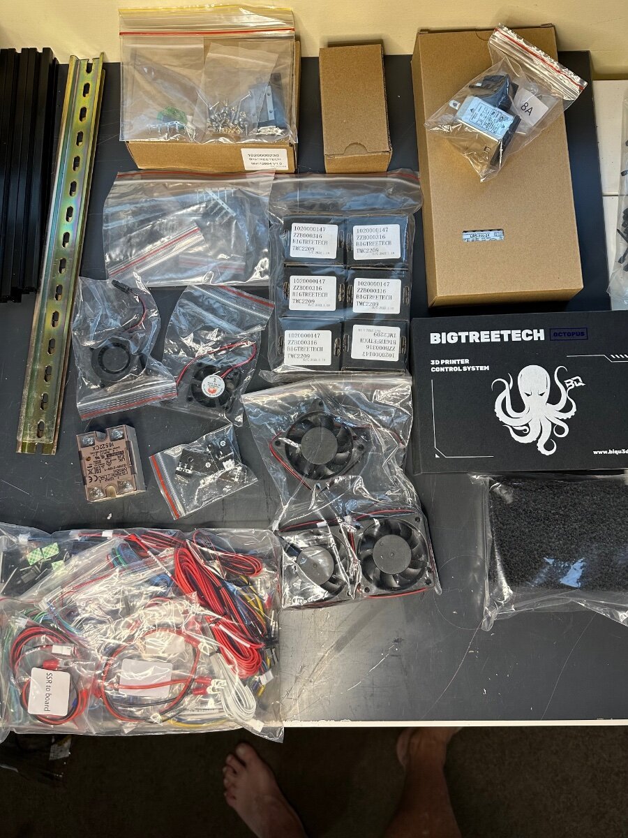
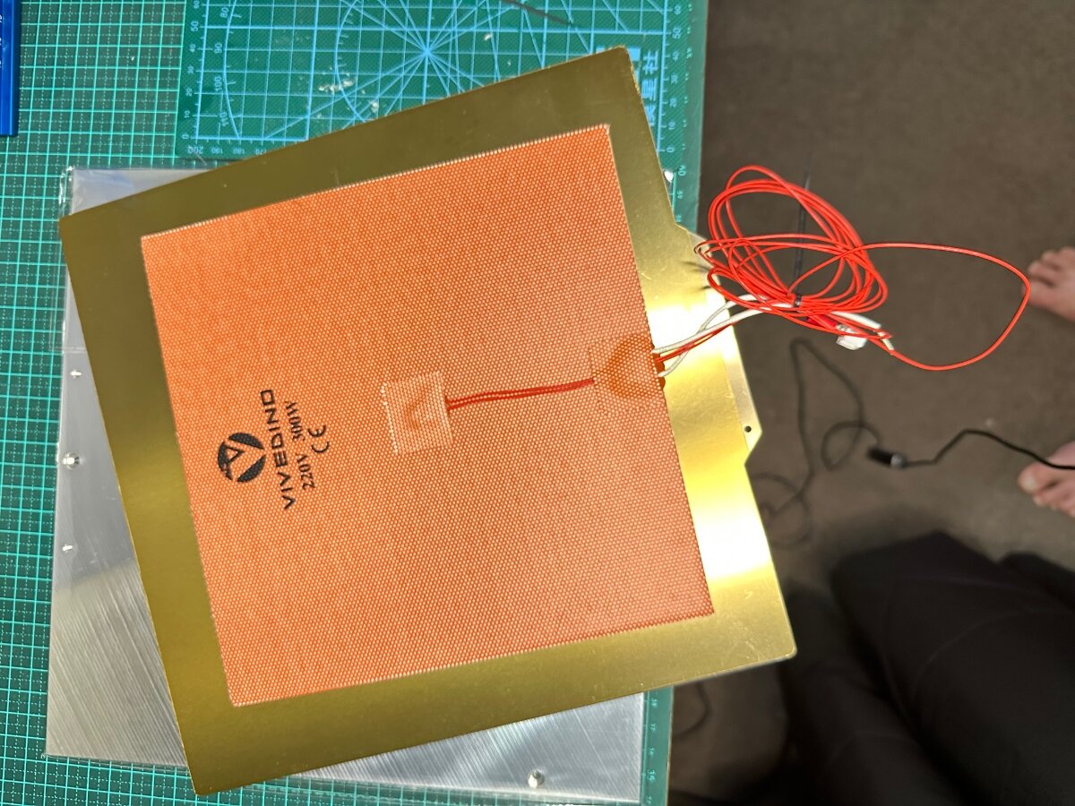
Milo V1.5 CNC Bench Mill Github Link Not a 3D printer but still going to be an interesting build The idea is to eventually make parts to replace the printed parts on the mill and for the Trident and V2. This is going to be a slow build, I'm self-sourcing the parts and will assemble them as parts are purchased and arrive. Years ago I purchased some parts to build a CNC machine but never completed the build. The frame and spindle were the last items to be purchased and built. Since then electronics for CNC have come a long way specifically the stepper drivers and motherboards. I already have the Nema 23 stepper motor but are larger than the suggested spec for the build. I'll be testing them with the Mellow 32bit FLY-CDY V3 Wifi Control Board when it arrives. These are the steppers I'll be testing: I have these Hiwin HGR 15 linear rails which I can cut to length, the blocks don't match the printed parts, but I can either modify the printed parts or order new blocks. The blocks alone will cost the same as purchasing a complete set of rails. The advantage of using Hiwin rails is the pre-load. Appreciate the lesson on the basic use of Fusion 360 that @Penatr8tor was kind enough to give me on Zoom. Parts ordered: Mellow Fly-CDY-V3 Complete Fastener Kit 2 x 4010 24V. Fans
8 points
-
Just learned that the Voron Phoenix, A monster Voron Build will be released first half next year. (originally planned for this December 23 or early January24) 600 x 600 build volume (550 in Z) build 4 separate beds for heating IDEX setup Canbus on the toolhead Upgraded CW2 (CW2r2) Nema 23 motors Upgraded TAP: VR2 rails 2 x Seperate rails that can individually be adjusted Tension adjustment that prevents "wobble" as per current TAP More Rigid design Dual filament runout sensors - one on the toolhead, another at the spool entry. Interestingly it still uses cable chains, but a difference in the path. The reason apparently because the umbilical option is not rigid enough. Most of the parts are machined though, with enough suppliers interested to manufacture these. The above build (by Max) is powered by BTT product with a printer board specifically designed for this build. I understand Steve form "Steve's Build" will be or is building one as well. Only question I have - where the hell do you put a monster like this? Should start a new section, we already have "printers for ants" - how about "printers for giants"
8 points
-
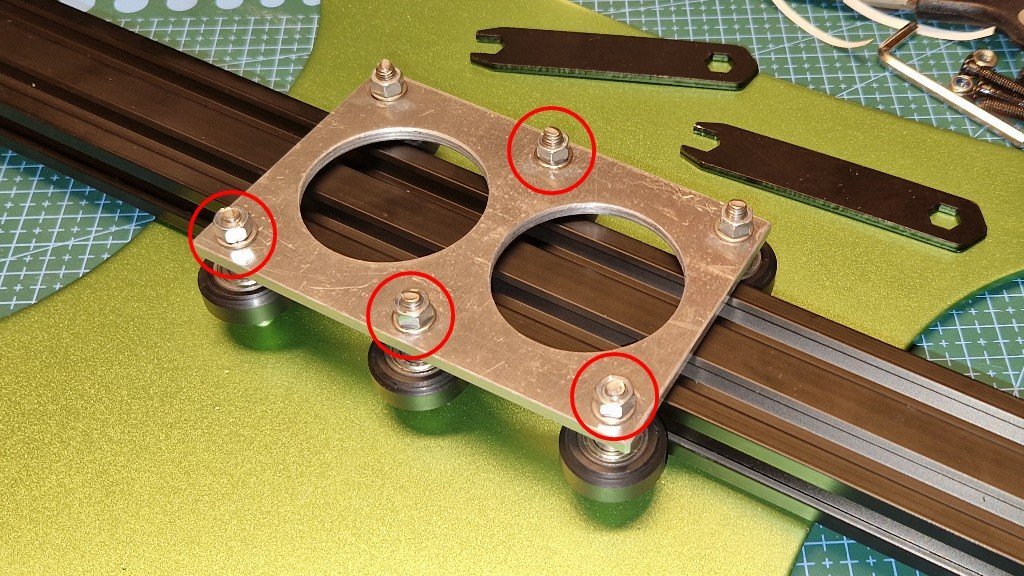
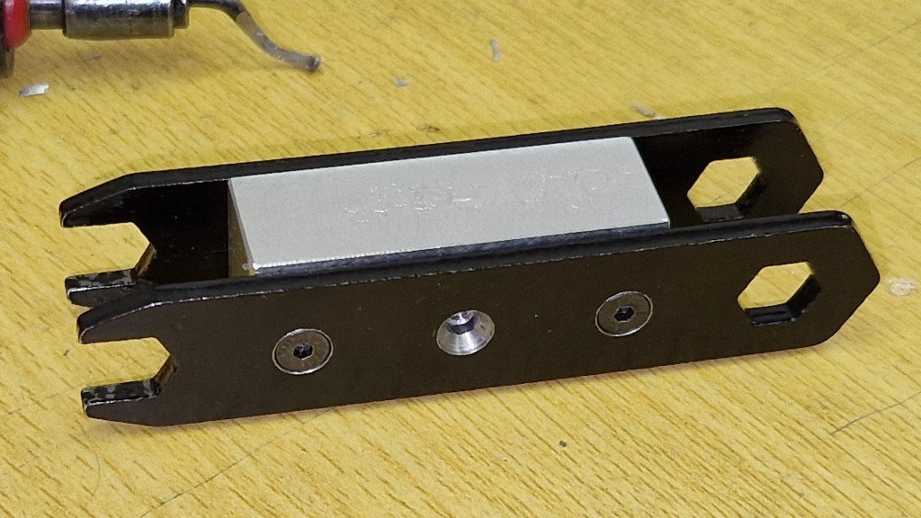
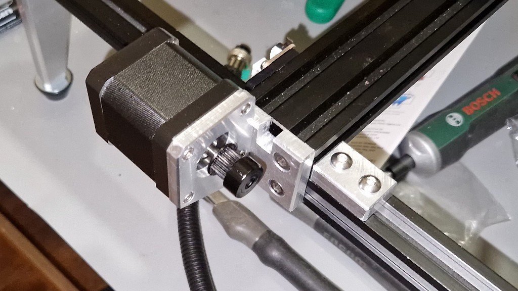
Hi everyone! Let's start a thread for comparisons of various Voron TAP solutions. Here's my gaggle of TAPS.... a Mellow CNC TAP, a Chaoticlab CNC TAP and a Printed TAP, left to right. I built my 2.4 with the Printed TAP, which has been working alright. After a recent Plastic Blob of Death (PBOD) event, which severely distorted the plastic TAP front, I decided to try a metal TAP, as I was never happy with the magnetic holding action of Printed TAP and also nearly all of the bolts had loosened. I liked the Mellow CNC TAP, but the estimated arrival was over a month away. So, I put one on order and ordered a Chaoticlab CNC TAP locally. Well, surprise, a few days later they both arrived on the same day! So a comparison is in order. Printed TAP. This is my baseline. Printed TAP R6 has been working well, even as most of the bolts had loosened over time. First layers are better than my PRUSA Mk3s+ had been until I sold it. Printing a new Front after the PBOD and tightening all the bolts surprisingly made little difference. I am not fond of the magnetic holding action of R6 TAP, nor am I crazy about the use of relatively soft ABS in the critical Extruder-to-X Carriage mount, but it has been reliable with Quad Gantry Leveling usually completing within 2-3 passes and with good first layers. By the way, Printed TAP is about 18mm thick in the Y axis, shifting it towards the front of the printer about 3mm, which can cause the Stealthburner to hit the doors. My R6 Printed TAP weighs in at about 85 grams as pictured, including sensor. Mellow CNC TAP. This is a beautifully made and packaged CNC machined aluminum version. It is dimensionally very similar to Printed TAP, uses the same Linear Rail, a very similar magnet arrangement and the same optical sensor. It comes with the sensor and necessary wiring and connectors, which is compatible with 5v and 24v. The magnetic action is very much stronger than my R6 Printed TAP. Mellow CNC TAP is also 18mm deep in the Y axis, similarly shifting the Y axis forward. Mellow TAP weighs in at about 75 grams, as pictured. Chaoticlab CNC TAP. This is a very nicely made CNC machined aluminum version of TAP. Chaoticlab has changed the design considerably, using a smaller Linear Rail and a non-standard microswitch style sensor that is 5v ONLY. It also uses a single magnet working against the Linear Rail instead of the Printed TAP dual magnet arrangement. The magnetic action is much less than that of the Mellow but considerably more than my R6 Printed TAP. The radically different design is much thinner in the Y axis, at only 13.6mm, meaning that the Stealthburner will no longer strike the doors and also reduces the moment arm of forces experienced during rapid movements. If one intends to use the original X endstop switch, a small adaptor must be printed out and attached, as seen in my picture. Chaoticlab TAP weighs in at only 65 grams, including the X endstop adaptor, as pictured. Instructions for Chaoticlab CNC TAP are not in the box but are easy to find on Github. Critically, one should follow the instructions on lubricating the linear rail before installation. A side view of Mellow, Chaoticlab and Printed TAPs left to right: So, in summary: Printed TAP works and is the standard arrangement. However, it is less rigid and heaviest at 85g and can be molten during a PBOD event. It also shifts the Y axis forward a few millimeters due to its 18mm thickness. On the other hand, replacement parts or updates can be easily printed out and implemented. Mellow CNC TAP is an all metal adaptation that remains very close to the Printed TAP arrangement. It is more rigid and lighter than Printed TAP at 75g, uses the same Linear Rail and Optical Sensor and has a much stronger magnetic holding action. It shifts the Y axis forward the same amount as Printed TAP. Chaoticlab CNC TAP is a radical departure. Like the Mellow TAP, it is all metal but takes advantage of this material to radically change the linear rail, sensor and magnet design and reduce weight still further to only 65g, including the optional X endstop adaptor. In addition, it is about 4mm thinner in Y-axis, negating the TAP shift forward as well as reducing the moment arm of forces acting upon it. Right now, I have chosen the Chaoticlab CNC TAP to replace the venerable Printed TAP R6 on my machine. I will post my impressions after some time getting to know it. However, any one of these choices are good. They each have their own strengths and weaknesses. Happy Printing!
8 points
-
I installed a V5 Duo V2 (Normal sized) Nevermore and 2 bed fans using the Elis bed fan mount for air filtering and speeding up the chamber heat up times. But how much did it really help? Since I apparently have too much time on my hands and nothing to print at the moment, I tested various combinations of these configurations to see how fast it heated up the chamber. Here is my setup: Voron 2.4r2 350 built from a formbot kit (now with many mods) 2x bed fans The fans in the Nevermore and the bed fans are all GDSTIME 5015 12V GDB5015. My chamber thermistor is sitting in a modified Z_chain_guide stl which has a slot for a thermistor to sit in it. This means my chamber temperature readings are being taken from the rear of the chamber, at whatever height I have my Z set at. For these tests I picked somewhere near the middle at 175mm. Is this the best place to take readings from for this test? Who knows. I figured somewhere near the middle was close enough for what I was trying to accomplish. I have my home assistant instance taking data from Moonraker, logging that into InfluxDB and graphing with Grafana. I was not able to get the exact same start temperature the entire time, but kept it within a few degrees, so not a completely scientific test but I feel close enough to draw conclusions. The bed is running at 110C I used the fan configs in the Elis bed fan github to control the fans. For the Nevermore during bed heating it runs the fans at 40% and then 100% when the bed reaches 110C. For the bed fans it run the fans at 20% during bed heating, then at 60% when it reaches 110C Ambient temperature in the room stayed about 1 degree from the what it started it when I began doing testing. Between 15C and 16C. Here are the results: To start I did tests with neither the Nevermore nor the bed fans running: Test 1: No fans running. No Exhaust fun running. Chamber being heated by the bed alone. 32 minutes from start till 30C 34.2C after 1 hour Test 2: Only exhaust fan running. Ran from the beginning of the test at 100% and the entire time. 47 minutes start to 30C 31.2C after 1 hour Here is where I started using the Nevermore and bed fans. Test 3: Nevermore only. Using the fan curve I listed above 22 minutes start till 30C 38.3C after 1 hour Test 4: Nevermore with exhaust fan running. 26 minutes start till 30C 35.2C after 1 hour Test 5: Nevermore and bed fans using fan curve listed above. 30C after 19 Minutes 43.2C after 1 hour Test 6: Nevermore, bed fans, and exhaust fan running. 30C after 19 - 20 minutes 40.1C after 1 hour So what conclusions can we draw from this? 1. Don't run your exhaust fan during your heatsoak sequence, every single configuration it increased warmup times, though with both the Nevermore and the bed fans running it wasn't enough to make a big difference. 2. A Nevermore alone helps noticeable with heatup times, but a couple bed fans will help a little more. Things I should have tested but didn't: Running the test with just the hotend fan running and nothing else to see how much that helped with heating the chamber. However for this to really be efficient, I would need the hotend down low to the bed to help push more hot air around, thus lowering my z, thus invaliding comparing that to the other tests (since my chamber thermistor is in z chain guide, which is attached to the rear gantry). Readings from lower to the bed are going to be much higher than at 175mm. The other thing I don't feel great about is that the Nevermore pulls air from the rear, under the bed, and pushes it up the front. The bed fans pull air from the front, and push it under the bed towards the back. I feel like this is cycling more air around the bottom of the chamber and not pushing it around the whole chamber as efficiently. Ideally I should mount the bed fans somewhere near the back so they are also pushing from the back to the front, however I have a decontaminator bucket one one side of the rear and I haven't thought of a good way to set this up yet.
8 points
-
Klipper pushed a large update, which seems to be the BTT branch of Klipper that supports the BTT Eddy probe. This has as consequence that ALL probes that have a klipper plugin, like Beacon and Cartographer, have to follow the same routine that the BTT Eddy probe requires. This has as consequence that these probes did not function as soon as the update was applied. Luckily the programmers quickly reacted and within a few hours there was already an update from Beacon and Cartographer. HOWEVER, with such a huge update, which cost BTT almost a year to (have) develop(ed), issues still may arise. So do like I did, and wait a bit longer before updating... Do not fix something that works perfectly. And if you already did update, and you have a completely useless printer and are considering going back to TAP or Klicky, run this command in your SSH, which will reset all updates from github back to the time before the BTT-Klipper. cd ~/klipper git reset 6cd174208bd9bbd51dc0d519a26661fb926d038a --hard After this, a reboot (power recycle) may be necessary.
8 points
-
Ah.. nothing beats a short and snappy title Building my 10th V2.4R2 or so, and this one is 100% for myself instead of selling it. Most things I be using here on top of the default Formbot kit, and adjustments to the default print parts are what I use in all my builds, this one has just some little extra or lets call it the "supreme" package... its still a Formbot and not sourced the parts by myself, but its a good quality kit, affordable, and they ship fast, if you like to build your own. I sell Voron builds, fully build, so I get quite a lot of questions, people who want to build themself a Voron, and I am a BIG supporter! Thats the whole idea of Voron. But I also know persons who are now trying to build their Voron for 3 months now, and still dont have it working properly, or at all... So... Hope this Diary/Guide is going to help you, I will try to make the parts that are most asked about better explained... I also get my information from others, there are way more experienced people out there than me, who wrote up great things, I will just link that way when we get there... What will this build look like, im based in the Netherlands Europe, so some links my not be useful, sorry. PS. I am NOT associated with any of these shops, dont earn anything on the links, etc, its just my build, advice is always welcome! Formbot Kit, this is where I order them - https://www.formbot3d.com/ - In europe? choose sending from Czech, and on Paypal payment, check the payment options to pay in Dollars, and let your bank do the conversion rate, for me this is about 70 bucks cheaper, paypal is expensive, shipping is free and there is no import, delivery in a week or so. This time im going for the Revo Voron, but normally I use the Phaetus Dragon HF/SF. Fermio Wire kit, nothing really wrong with the default wiring, yet its bulky and had breaking wires ones. Fermio wire kit is expensive, but awesome. https://fermio.xyz/fermio-labs-gmbh/voron2-wire-harness-btt-octopus-350-spec/ - about 125 euro, all Helukabel Heluflon®-fep-6y wires.. uhm, yeah, whatever, its good! Keenovo bed heater mat - Nothing wrong with the default Formbot heater mat, I just want to try this one: https://fermio.xyz/keenovo-international-group-limited/keenovo-silicone-heatmat-340-x-340-mm-230-v-ac-500-w/ - its a bit larger. Stealthburner with leds, I am a lazy ass, so I buy the LED string - https://fermio.xyz/fermio-labs-gmbh/stealthburner-rgb-led-kit/ its only 6 bucks, and has the thin high quality teflon wires, I just cant beat that price, by burning my finger on clumsy soldering... I am using different prints than the default ones where there are bearings used, especially toothed bearings.. I use smooth pins instead of M5 bolts and smooth bearings instead of toothed for this you need adjusted prints, some amazing guys made this already, and I will link to them later. Smooth pins are available on Aliexpress, or whatever you like. Then some default other wonderful mods, Klicky, PurgeBucket, other Front Idlers, Stealthburner, belt covers, Panzerball feet and 5" Touch display. Using Extrudr ASA Filament (big fan) but I am not stuck to it, I just dont use the cheap stuff, never been successful for me... I may go for another Red Bull theme here... Fermio custom Aluminium Composite panels. - https://fermio.xyz/fermio-labs-gmbh/voron2-v2.4r2-aluminium-composite-panels-350-spec-black-logo/ Other extra things may follow....along the way.. INDEX - to direct you directly to the posts and avoid all the useless comments here Setting up the frame(work) - Click here to go directly there inside this post. Setting up Z Rails, mounts/feet and motors and Z idlers. Page 22-51 in the manual. Click here to go directly to the post in this thread.... A/B Drives and Front Idlers. Page 62-81 in the manual - Click here to go directly to the post AB drives - Front Idlers Gantry! Page 82-107 - Click here to go directly to the post - Gantry! Belts Z and AB. Page 108-146 - Click here to directly go to the BELTS post.... Electronics and Wiring! Click here to go directly to the electronics/wiring post Software setup Klipper/Mainsail (sorry my choice!) - Click here to go directly to Software installation guide Follow this topic if you want updates!8 points
-
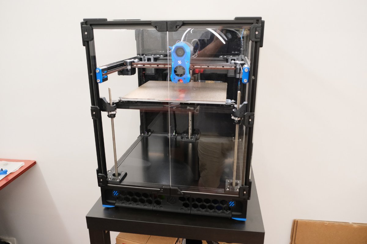
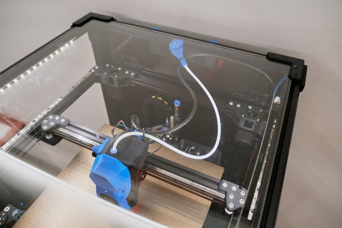
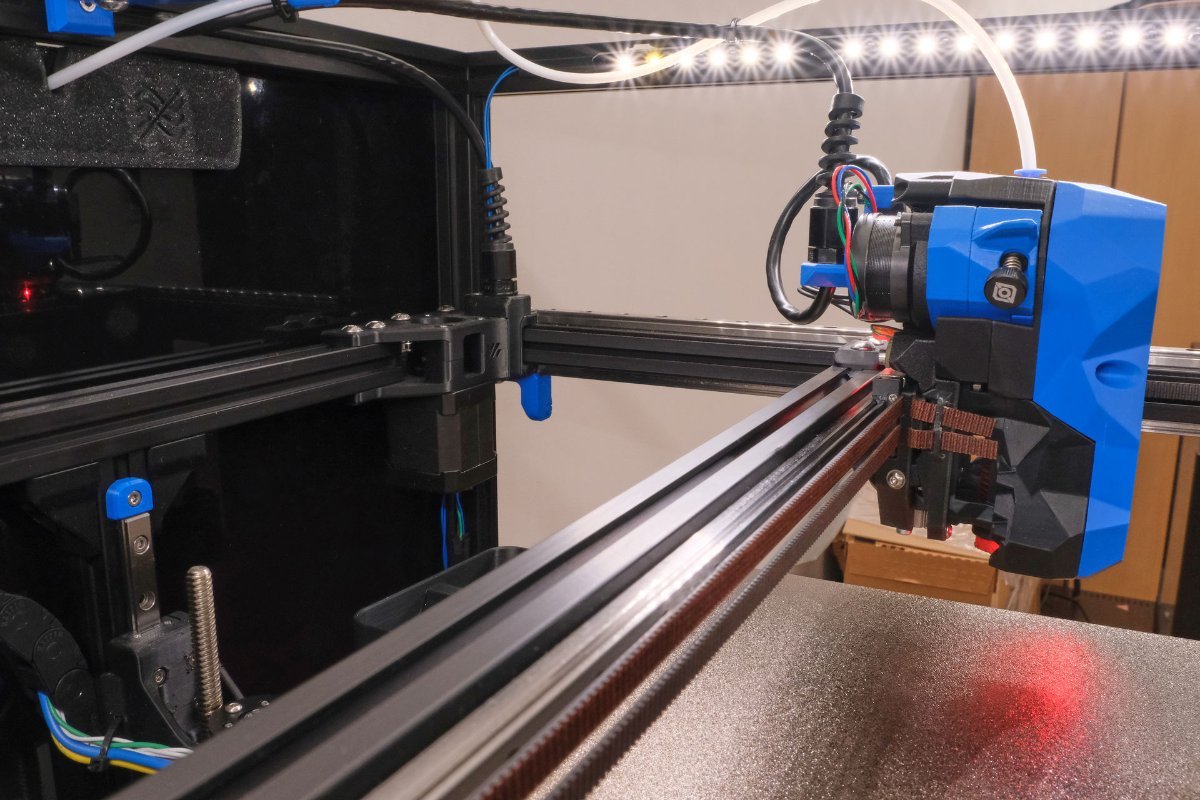
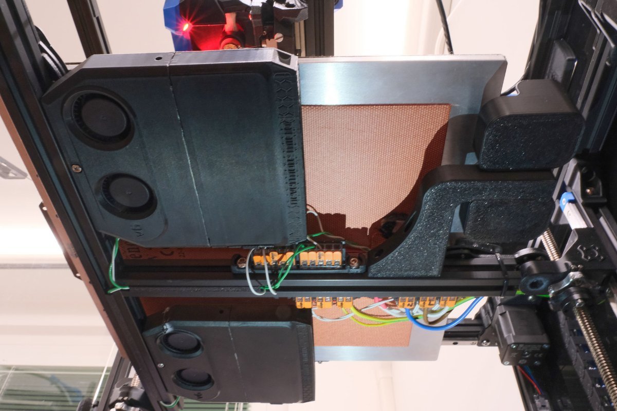
I wanted to re-visit this thread and give an update on the VzBot. I upgraded the camera. I had installed a Waveshare OV5640 camera and it was ok but, wasn't good enough for my liking so I ordered one of Luke's Laboratory's cameras. The Waveshare was a slender strip format PCB with a standard 5 MP camera where the Luke's Lab Cam is a square Ardu-cam style PCB. I downloaded the standard case and mount for it and it fit nicely where the other camera was. The camera output is miles better and has IR LED's and a sensor that swaps to night vision mode when the lights are low. Luke's Lab Camera with normal lighting (screen grab from Klipperoid on my phone) Night Vision (all lights turned off in the room). Pretty impressive IMO. I also ordered a Nozzle ADXL345 from Provok3D. Below are the results. On the left is no input shaper. Print is Overture cream Blue PLA @205c - 65c and ~150 mm/s on outside surfaces. Right side is the same print with input shaping turned on. Below is a 3rd print I did where I increased the global speed from 100% to 150% with no visible difference in output (far right part). I then changed filament to some Polymaker CF PLA and found something to print that I figured might be a good test to see if I got any ringing. No ringing but I did get a little line at certain points along the Z axis. It looks like it's function of the slicer at that particular junction. Regardless, I still need to tweak some more, or more accurately... I'll be tweaking forever as per usual, , but for now... I'm really liking the output of the Vzbot. One thing I didn't mention is... I was using a .6 Diamondback nozzle before and have since switched over to a .4mm Diamondback. All prints were with the .4mm nozzle and 205c print temp. I also created both PLA and ABS/ASA pre-heat presets where, for PLA, it sets the nozzle to 150c and the bed to 65c. When I hit print... the printer immediately springs to life homing all axis' and performing a 15x15 full bed mesh @ 500 mm/s using the Beacon probe. All this in under 30 seconds. Getting the nozzle to temp and printing takes another ~30 seconds. So, 1 minute from click to print. I am definitely not complaining about that one bit. If you're wondering about the cable bundle in the back corner... It's from the LL cam. The previous camera cable was too short to make it out of the rear panel, so I used and extension cable. I bundled the cable temporarily so didn't have to access the rear and re-route to the pi. When I attached the ADXL345 to the nozzle... It turned out that, all I needed to do was disconnect the camera and plug in the ADXL. So, for now... I'm leaving it. I'll probably shorten it later on.
8 points
-
I'm going to add this to the list of must have tools... I've had this little tapered hole reamer/deburr tool for ages. The acute taper lets you deburr inside of a counterbore which is usually really hard to get to. Once you try one... you'll be sold. Anyways... They're cheap, something like $11 US on Amazon
8 points
-
Hi everyone, I have been working on this project for quite a long time now. About 6 months - 1 year and it is finally ready to be published. This is the main site: 3D Printer Color Configurator (3dprinter-color-configurator.com) This is the site for voron printers: Voron Color Configurator (3dprinter-color-configurator.com) I have developed a site/tool where you can create, visualize and configure how you want your Voron color theme to look like. Users can now create everything from the default color groups (primary and accent color + chain and frame) to a very unique looking build, where up to 8 different groups of parts can be colored. While you find the color theme you want, you can also configure the printer you are building, download that configuration and afterwards go to the download center and fetch the STL bundle (ZIP) that corresponds to the configuration chosen. My Color Configurator currently support all Voron Printers with the default config, as well as a 8 accent config. Voron V2.4 also has 7 accent version. All colors used are based on eSUN ABS(+) and Keene Village Plastics (ABS), where each and every color is labeled with the color name they represent. OBS. I am not working for or is affiliated with the Voron Design Team, but is working on an individual project of my own free will. All credit for the CAD and STL files goes to the Voron Team. In the future, I will potentially add more printers from other brands. I am open for feedback, so contact me by mail or here on the forum, if you have any problems, can provide additional information or informational fixes, grammar fixes or have suggestions for the website. Your suggestion will be added to the roadmap if it has enough interest. An example is shown below: Then download configuration: Voron-V2.4-8accents.pdf And download the STL bundle (ZIP) from download center: Happy designing
8 points
-
Well another to add to the list are the Knipex Plier wrench for inserting neodymium magnets into the printed parts. Saw this on Steve's builds and @Buurman re-enforced their use. So early Xmas present to me. Will certainly try them out when I get to installing the Voron Tap.
8 points
-
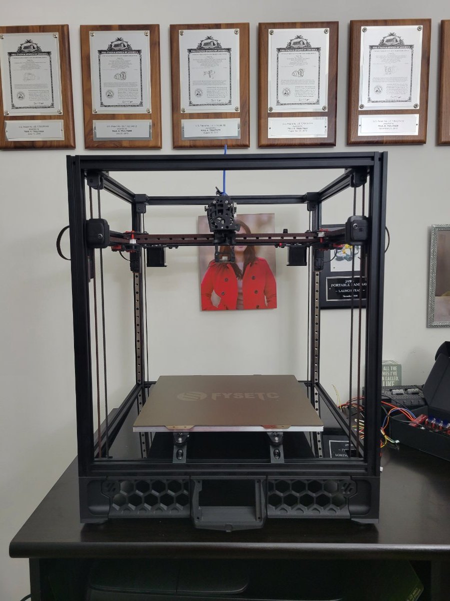
Print Volume: 180 x 180 x 200mm This is a design that I am still finalizing but the Linear rails and plexi panels should provide most of the structure. It is a cross between a V0.1 and a Trident using the bed from a Prusa Mini for the build plate. I don't know how quickly this will get built but I am starting to print parts already and I have all of the components in hand.
7 points
-
For those interested - a KlipperScreen add on for the Box Turtle running AFC software. Github repository:
7 points
-
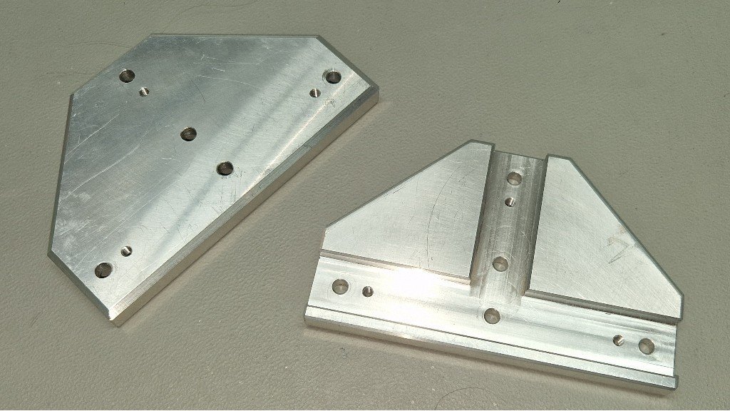
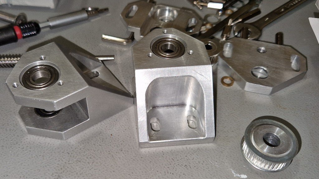
As the title states, I picked up a Milo V1.5 110v US Kit from Hector at Fabreeko last week while I was in Fort Lauderdale during the holidays. Here we are getting scorched by the afternoon sun, Milo is in the trunk with Steve Builds old Subaru that Hector bought from him in the background. Awesome guy, he gave me a full tour of his very impressive shop and warehouse. A number of things he sells he makes himself on a HAAS H2 mill and laser. I have to finish up my Voron 2.4 refurb first then I start on the Milo. Of course, there will be a build diary so stay tuned. I'm going to build a bone stock Milo at this point (famous last words, I know) if I do anything it will most likely be chip/swarf management related. I'll be printing parts in anticipation of the build. When I get those going I'll start a diary. Cheers everyone, Hope you had an awesome holiday! Pete aka Penatr8tor
7 points
-
Eddie Probe Comparison: Feature Beacon Probe Cartographer IDM Packaging Plastic Box. USB Cable and Plugs included Cardboard Box, Connectors and short cable included Plastic bag, connector included no cable Connection USB USB / CAN USB /CAN Temperature Limits No temperature warnings No temperature Warnings Warnings - coil temperature exceed limits Performance Very Reliable and consistent (4months +) Very reliable (3 weeks) Inconsistent readings (2weeks, then changed) Installation USB from probe to Raspi Can H and L spliced into toolhead, 5V and GND from probe input Can H and L spliced into toolhead, 5V and GND from probe input Cost 1.AUD$149.00 incl postage 2.AUD$219.00 AUD$55.00 AUD$64.95 Supplier 1.Beacon 3D (USA) 2.PhaserFPV (Aus) Orvil3D (Australia) Budi Store (Aliexpress) · Beacon Probe: Plastic box with connectors, probe and USB Cable · Cartographer: Cardboard box with connectors and pre-crimped cable · IDM: Plastic Bag with one connector and crimps. No cable. Here are the probes in order: IDM, Cartographer and Beacon: Each probe has identifying marks on the coil, but the Beacon Probe has the name written on it as well. Whilst I had the Trident 300mm in for some repairs and maintenance, I decided to try out the IDM Eddie scanner (Canbus) that I got from Aliexpress. First impression was not good. The probe was delivered in a plastic bag, no cable, no instructions. Went ahead and installed this on both the Micron 180 and the Trident 300. Had trouble with the alignment of the probe PCB mounting holes on both printers with the IDM probes. They were out of alignment by about 1mm and had to enlarge the mounting holes on both probes. The probe on the Micron was mounted to a printed piece which could have accounted for this, but the one on the Trident was mounted on a CNC carriage from Funsor. Also test fitted the Beacon probe on the Micron and mounting holes aligned. Installation after that, was simple – mounted the probe and crimped a cable – one end has 4 wires from a JST connector for the probe, the other a JST connector for the toolhead board and spliced the CanH and CanL into the existing can cables on the toolhead. Had to update the firmware on the IDM probes. Very simple process, as I followed the instructions on the cartographer github page. Calibrated the probes and set the Z-Offset as per the instructions. The Beacon probe (Rev D) has been installed on the VZBot and has been operating for a few months now – USB from board back to Raspi. Since then Beacon released the Rev H which is larger, but flatter than the Rev D. The overall dimensions on protruding behind the printer is similar though. Just less height. The IDM probe on the Micron has been nothing but trouble. Seems to be losing the Z-Offset and routinely comes up with “temperature out of range for coil – shutting down”., which I suspect is the cause for the inconsistent Z-Offset. The IDM probe on the Trident has given the occasional “mcu lost communication with probe” error. I put this down to a bad splice on the CanH and CanL connections. Or maybe it is the Canbus bridge on the Octopus board? (Had this issue on another Trident – may switch to a UTOC 1 on this whilst it is out for service) Since installing the beacon probe (months now – Rev D version) – have not had to touch it. Works flawlessly. Since installing the IDM on the micron – ready to chuck it out. (Must qualify and say this was the cheapest probe I could get on Aliexpress.) Did this and replaced with a Cartographer probe (CanBus) - No issues as yet - works flawlessly Since installing the IDM on the Trident – some communication issues with the probe – will need to give it a bit more time. Did that and all issues settled. Been running for 3 weeks now and no problems. Had to take the printer out of commission for some maintenance and upgrades. Think I will change to a Cartographer Probe. Picked up some Cartographer probes from a local supplier.Very cheap indeed - AUD50 for Canbus and AUD55 for CanBus/USB. The Cartographer probe performs very well, probably on par with the Beacon so far. But it is early days. Will have to see what time and the high chamber temperatures does in the long run. What I love about the cartographer is that it is Canbus - no bulky USB running to the toolhead. Still just the 4 wires in the umbilical. Which is best? - you decide
7 points
-
Hey all, I just installed an active chamber heater in the Trident! Also doubles as a bed heater (active--thus the motion blur). For whatever reason he's become fascinated with the printer lately. Now I really have to keep on top of cleaning the purge lines & skirts; can't have him eating them. Also have to keep the top panel on even for PLA because, yes, the dumbshit tried climbing in while it was running.
7 points
-
https://github.com/Diyshift/3D-Printer/tree/main/GT2 Belt Tension Meter Did you try this tool ? I made it, calibrated it "the alternate way", and it seems to produce repeatable results. (looks like a hit and miss syringe, but it isn't)
7 points
-
I am posting this with my medical hat on, not my 3d printing hat Just a caution to all of us to take all possible precautions to protect our health when enjoying this great hobby. Came across an interesting article, highlighting the importance of good ventilation for your 3d Printers to minimise potential health hazards. Some interesting snippets from the research. Those interested in speed demons: More concerning is the following finding: And it is not only the smell of ABS we need to be concerned about: Seems PLA is the safest option: And in the color debate: Let's all take care and stay healthy.7 points
-
This is quite misguided. I am a director of BTT and oversee the design process. I can assure you that BTT makes every effort to investigate issues, solve them and then iteratively improve on designs. A perfect case study is the thermistor circuit in question. Some on this thread have asked why it is designed the way that it is and our answer to that is simply this: try to kill our MCU by shorting 24V to the thermistor input (more common than you think when people clean with a wire brush and the hotend is active). You simply can't because the MCU is well protected by a high input impedance and any additional power is shunted to the power rails. This will not be the case on some other manufacturers with different circuits. We don't have a 100k resistor not because we want to save the absolutely, completely, thoroughly insignificant amount of money that a resistor costs to place but rather because we used to ground these holes and that caused ground loops. We never considered that a slow discharge would help with ESD events but now that is something that we are going to take into consideration and use to iteratively improve. Additionally, we will also be adding some ESD absorption circuitry to the thermistor input to save the thermistor in case of an ESD event.7 points
-
Same Thread: Updated for 2023! Researching, purchasing the printer parts of the build list and waiting for parts is only half of the battle. While many Voron builders have many of these tools on hand, and we hop most have familiarity with soldering, there are some tools that make the job MUCH easier, safer, and provide professional quality results. This is the Mega List for all the recommended or required tools for your Voron build. First and foremost, crimper are really important for your Voron build. With the amount of wiring required, you will thank yourself to invest in high quality crimping tools. Frequently users ask if tinning and soldering joints is an alternate option. While it may work short term, this is a much greater risk of the joint failing. Typically this is due to the stress of movement, or weakening from the heat created inside the enclosure and around the hot-end during printing. Wire Crimpers At least 1 Required Don't skimp if at all possible, the Voron build requires a bunch of crimping, this tool will last years! You will require at least one of these, if your doing only 1 build the 3220M will work - If you intend on doing anything more, the the general consensus in the community as a whole highly suggests the Engineer PA-09 as a great best value option. Molex Wire Crimper - $100 - Molex Wire Crimping Tool Engineer PA-09 - $55 - Molex Wire Crimper Tool <- Most Popular Option IWISS 3220M - $23 - Molex Wire Crimping Tool IWISS 2820M - $24 - Micro Connecter Crimping Tool IWISS SN-025 - Dupont Crimper Tool Ferrule Crimper Optional (This can be done with non-specific tools, but be prepared to damage end frequently, and spend time cutting and re-stripping wires) Ferrule Crimping Kit - $29 - Kit with ferrules and crimping tool Terminal Crimper Optional (This can be done with non-specific tools, but be prepared to damage end frequently, and spend time cutting and re-stripping wires - only 1 needed) IWISS 1442L - $33 - Open Barrel Terminal Crimping Tool Titan 11477 - $20 - Open Barrel Terminal Crimping Tool Wire Stripper At least 1 Required (Technically optional, but don't nick wires, or cut your thumb! ) For Voron Electronics and builds you will need a wire stripper capable of stripping 16-26 GA wire, make sure your stripper is capable of stripping thin 26 gauge wires. Engineer PA-07 - $26- Manual Wire Stripper Tool Ideal Industries 45-097 - $58 - Auto Wire Stripper Tool Screwdrivers / Allen Wrenches Allen Set and Screwdrivers are Required Metric Allen Wrench - $14 - Try to source with rounded tips, easier to reach some odd angles, from at least 1.5mm - 5mm Screwdriver "kit" - $14 - or small common screwdrivers Knippex Plier Wrench - $90 - Featured on "Steve builds", a fantastic tool! Soldering Iron / Heat Gun At least 1 Required A soldering iron is also required for the heatset inserts. Any soldering iron will work for the entire Voron build, you do not need to go overkill here. TS-100 - $72 - Portable Soldering Iron Solder Rework Station - $60 Great mid budget option for adjustable temps and a hot-air rework suitable for heat shrink duties Adjustable Iron - $15 Solder 6337 - $18 - Flux core solder Multi-Meter At least 1 required (Technically optional, but a multi-meter makes setup and troubleshooting MUCH easier! ) Fluke 117 - Professional Multimeter AstroAi - Basic Multimeter Measuring Tools Optional Metric Calipers - $15 Any Digital caliper should work Benchmark Tools 4666-06 - $7 - Machinists Scale A fancy accurate ruler, 6" or 12" Machinist Square - $13 Improves squaring up frames, don't drop this it could through it out of square! Specialty Tools Diagonal cutter required others optional Klein Tools D275-5 - $10 or Hakko-CHP-170 Micro Cutter - $8 - Diagonal Wire Cutter While the Klein tool is high quality, these are inexpensive and included with many commercial DIY printers 6" Mini Needle Nose Pliers - $9 Don't go overboard, just holding tiny parts where you fingers don't fit! Milwaukee 48-22-9215 4 PC Hook & Pick Set - $17 Great for managing and pushing wires and parts in tight spaces. Printable Tools Optional Nozzle Torque Wrench - https://www.thingiverse.com/thing:4738816 Tape Optional Kapton Tape - $8 - Optional, protects electronics for accidental shots, heat resistant Spectape ST501 - $15 - Double Sided Tape (Door mounting) Grease Optional (Highly recommended to preserve accuracy and increase longevity of your printer) Super Lube 92003 - $11 - PTFE Grease for plastic on plastic parts MG Chemical 8461-85ML - $10 - White Lithium grease for metal on metal parts If you have any recommendations or if I missed a few required items, please post below and I will update the list to include other options!
7 points
-
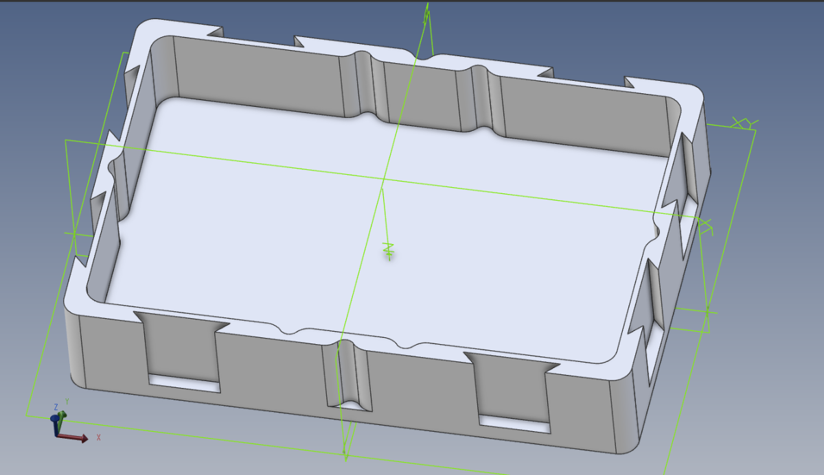
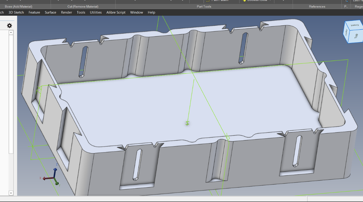
OK, I've been farting around with an upgrade. I currently have a BTT 5" Klipperscreen. It's nice, it works but... I want MOAR! Back when I was building my VzBoT, I took advantage of a discount and bought 2 Mellow 7 inch LCD touchscreens. I figured I'd used them somewhere and so I'm using one on my 2.4 refurb journey. As per usual... There are no CAD models of the display so first order of business was to reverse engineer the sh!t out of this thing... Sorry for "The Martian" reference LOL. Now to design some printable parts... I think this is a good opportunity to give others some insight into how to model custom parts for your printer or anything really. I'm doing all of this in Fusion 360 BTW, no fancy plug ins... just stock Fusion. So, now that I have a model of the display, the next I want to do is to save the display so that I can insert it into whatever I want to in the future. Now, we create a new design in Fusion 360 and we insert the display model into the current design. This will be my reference model, it's 100% accurate and whatever I design around it, I know, will fit (or at least that's what I tell myself LOL). At this point you need to create a mental strategy of what components you'll need to design. I decided that I would need a minimum of 3 components, a base plate, a bezel and a bracket or mount to attach the assembly to the printer. Now that the display is inserted, I ground it so that it cannot be accidentally moved around and screw up my design (just right click on the inserted file in the browser and select ground). Next, I create 2 components in Fusion. Right click on the topmost component on the left and select "New Component" and create a Base Plate component. Then repeat and make a Bezel component. Ok, Let's model a simple bottom plate that the screen and bracket can mount to. I start by activating the base plate component (press the little circular button to the right of the component name). Then I create a sketch and, the first question that will pop into your mind will be... Where do I sketch? And that leads to the next question which is, where does the display attach to the base plate? That is where you sketch. The base plate attached to the 4 standoffs on the display, so I click the little donut shaped surface of one of the standoffs. That will be my sketch plane and no matter what I change in the future... that sketch is locked to the standoff. Next we start sketching and we draw whatever geometry is required to get a shape that can serve as a base plate. I'm not trying to include everything at this point. Just a rectangular plate with 4 holes. Once our sketch is done we use the extrude command to create a solid object. This will be the formula moving forward for all components and all features, BTW anything that you create that displays an icon on the bottom time is referred to as a feature. Fusion is a feature based solid modeler and we make features. The timeline on the bottom looks like this. Here are the features you see above (the play buttons on the left are obviously not features). So, you'll see 3 features with a green line above and 2 with an orange line above them. The colored lines match the color of the component, the green line denotes the main component and the 3 features from L2R are the inserted display and the two components we created (base plate and Bezel. The features under the orange line are the sketch and extrude command. If you want to make any changes... right click and edit the feature. Now I want to point something out... every time you reference a feature from another component, you create a dependency. Right now, the base plate is dependent on the display, more accurately, the face of a standoff on the display and since I also created other references (purple lines) there are other dependencies as well. Just know that you will change things and as a result, you will disconnect dependencies that will need to be erased or reattached. Ok, enough talk, below is the extruded base plate. I went with 5mm. I then created another sketch on the bottom of the plate to do a cut extrude feature to create a rectangular hole and I also created some chamfers on the corners. I think you see how this works... Sketch -> extrude, sketch -> revolve, etc, etc, So far so good on the base plate, we have enough geometry to start on the bezel. And like the base plate component, I activate the bezel component and start a sketch. Again, where do we sketch from? Well, we want a wall that encloses the perimeter of the display, and we want it to start at the bottom of the base plate and grow upwards to the screen part of the display. So, I choose to use the bottom of the baseplate as my sketch plane or surface. Form there I sketch a perimeter and extrude that up to and just a little bit beyond the height of the screen and extrude the perimeter up. Then another sketch for the top and extrude that and another sketch for the step in the bottom and so on. Pro Tip: A good rule of thumb is fillets and chamfers at the end, no random fillets inserted throughout your model, this creates dozens of unwanted dependencies that will most certainly blow up in your face when you make a change down the road. While this might look good enough for most... I want to add some cosmetic features to give the part a more Voron like design aesthetic. Next, I start a new part and create a front skirt mount for the display. Without going into excessive detail. I grabbed the front center skirt from the Voron supplied 2.4 CAD model and cut away all the stuff I didn't need and added 2 wings to mount the display. I had to play around with the height and angle and after I got it to a good location I discovered that there was no way I was going to be able to get my finger on the top to press the control buttons. So, I designed some lever style buttons. When I modeled the display, I also added the 4 switches along the top. Since I already have them in the model. I can easily create a blade that fits into a slot with a little nub on it to press the switch. On top of the switch is a button that will poke out of 4 small windows modeled into the bezel. I also added nubs to snap on the bezel. I designed the paddle in two pieces so that they could be printed flat and so that the layers would be oriented perpendicular to the bend moment. A clearance of 0.1mm made for a nice press fit. Here's base plate with the paddles inserted and bezel. 4 M3 screws will hold in the display. Finished enclosure design. Completed assembly. How do they print? Well, everything was designed to not need any supports all corners were chamfered so that the parts grew at a 45 degree angle up wards. I did use a brim on the chassis mount, still need to hit the edges with a heat gun. Overall, no fails on the printing. I did have to ream out a few tight holes. Anyways... here's how it turned out. I mean if this doesn't make you want to learn CAD, I can't think of a better reason. Next update I'll have it installed.
7 points
-
So, I recently purchased a 2.4 kit from Siboor. Excellent kit! I started the build 2 weeks ago and I powered it up today. I had a few minor issues, I forgot to power the Rpi and the SSR, but those were easy fixes. The A and B motors were swapped so it didn't want to home. I missed 2 jumpers in the BTT 2240 CAN board, so it errored due to the end stop being triggered. Oh, and I had to reverse some pin logic in a few spots and change the bed size. Between just double checking my work, and a few Google searches I was able to get all these issues fixed. So far, I had got it homing, QGL is working, Bed mesh is good, PID tuned the hot end and bed and I ran input shaper. No melted filament yet, that will be tomorrow. So, its a 2.4 R2, all CNC parts, Tap, BTT CAN 2240, 5in touch screen with Klipper screen, HiWin Rails, and Chaotic Labs CNC Tap is in the mail. Phaetus Dragon HF hotend. I'm also working on a new Kinamatic bed, I hope it will be simpler and cheaper using mostly easy to get/make parts. So far this has been a great build and a lot of fun. But not it has me thinking about building a V0.2 or a Micron. Yes, the build plate is off in the picture. Half of this build was done in a hotel room where it is currently.
7 points
-
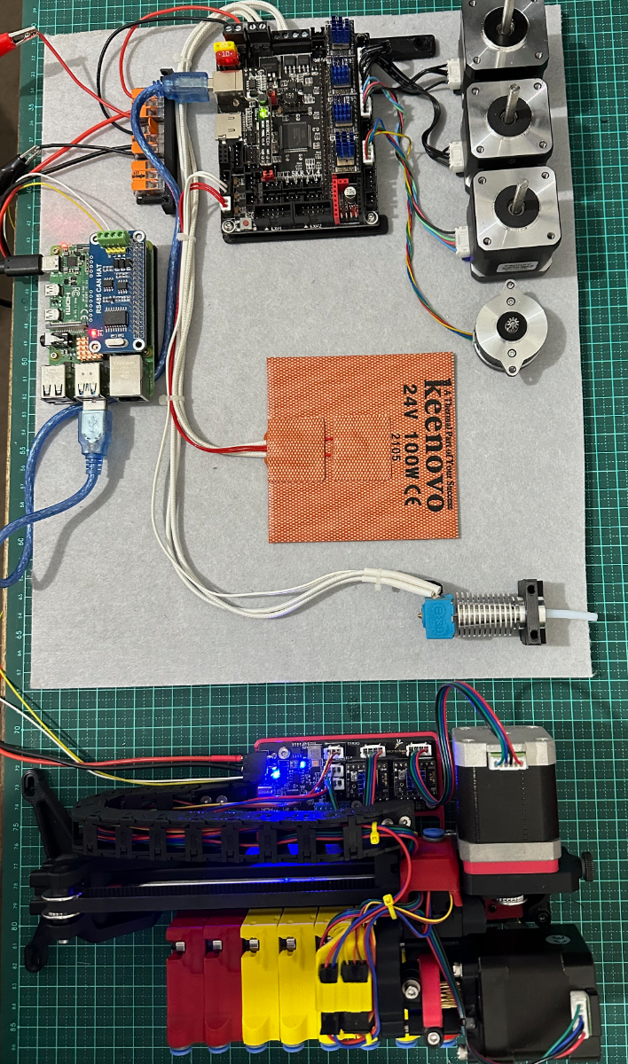
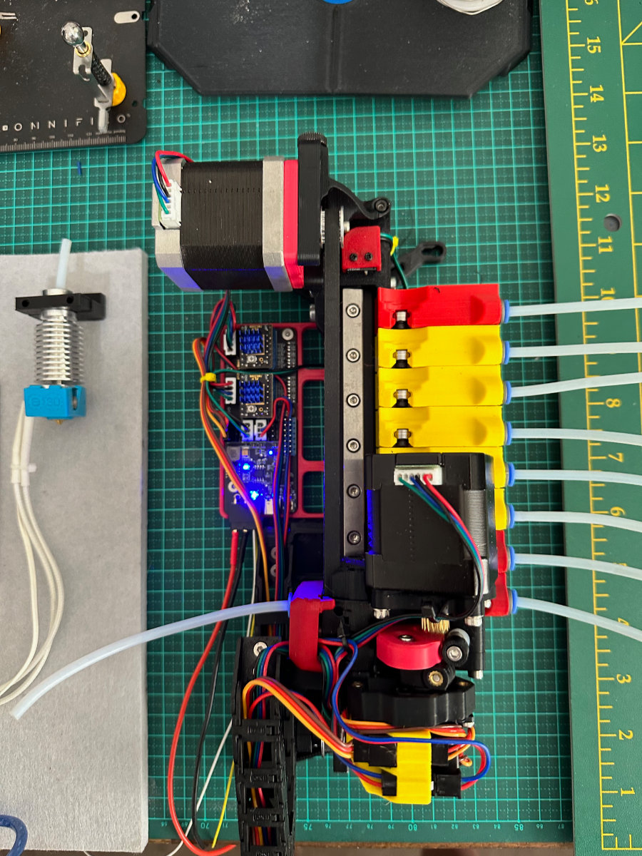
Well had some time yesterday and today and decided to finish the wiring, testing and in effect the build. Used a Mellow Fly ERCF Canbus board so the unit can be operated independently from a specific printer. Can easily be adapted and wired up to any of the printers running an octopus board with Canbus. All in all this was a MUCH easier build than the ERCF v1. The calibration was painless and testing the loading of the lanes went without a hitch. All testing was done under "lab circumstances. A while back I put together a platform with all the components needed to test 3rd party devices such as the ERCF and now the tradrack, and flashing Canbus toolhead boards. (SKR 1.4, Raspi Pi with Waveshare CanHat) Next up (seperate build log) will be the filament cutter. Still need to decide which printer this will go on. Looking at the color scheme it may go on the 2.4 300mm build as the color scheme of that printer is yellow and red. This will be a slow integration as it is not a priority at this stage. Loved this build due to its simplicity and ease of use. Building and calibration, if I had to choose between the ERCF (V1) and TradRack - I'll go TradRack. Printing wise - cannot comment as I have hardly used the ERCF before moving it on and have not used Tradrack on a printer. I just LOVE building things - it is my de-stressor. Thanks for reading and following along.
7 points
-
Time to finish things up. Since my last post, I installed the electronics, setup the software, installed some more mods, went through the tuning guides, also tuned some filaments, and I am very satisfied with the results. This Trident is way better in every way than my previous printer. I've been actively printing with it for over a week now, but let's step back a little. Like @claudermilk proposed, I started using the Nevermore as bed fans instead of having them separately. I installed two of it though :D:D:D More circulation, more filtering, or less often cartridge-refill. Between the Nevermore and the enclosure, I can reach above-60°C chamber temperatures. Good. It wasn't on the mod list originally, but I also added a purge bucket and nozzle wiper. When it came to the endstops, I realized the stock solution isn't good for an umbilical setup and needs to change, which I did not foresee. After looking at some mods and evaluating my options, I decided to try sensorless homing, and it works great! Not only simpler, but less cables and no mechanical switches. Just what I love. Many days were spent trying to print some additional parts on my old printer. Some succeeded, most took multiple retries, and some failed completely. I lost several days due to this. Once I got the Trident printing, it was a walk in the park. I can already tell it is going to be a lot more reliable printer, with excellent print quality (I already tuned many of my filaments), and it is even faster. I can print 1.5x-2x faster without obvious quality loss. Printing speed wasn't a concern when I decided I'm going to build a Trident, but it certainly is welcome. The printer is louder than my meticulously silenced Aquila, but this was expected. It is not that bad though. I consider the printer done. I am still making adjustments to the Klipper config files here-and-there (adding some new macros, pause/resume, adaptive meshing etc.), but none of these are really important. I'll also be requesting a serial. Next and probably final diary entry will be about some print samples and the Galileo2. I also plan to edit the first post and link all the mods I've used in this project, for the interested.
7 points
-
I do. I use windows because the software (CAD and FEA) I've been using for my job for the past 40 years doesn't run on a MAC. Certainly, there's more support today but primarily it hasn't. And FWIW... a MAC is just a PC with Apple branding and Apple's OS. Yes, some may argue that Apple uses their own processor on some models but for the most part they run, Intel Core series processors, regular old DDR memory, Nvidia graphics cards and a PC hard disk drive. So, when you boil it all down, what you have left is a PC running Apples OS that costs 3x as much as it should. Now don't get mad at me for being honest... we all know that we're all benefitting from the PC open architecture that created all the performance and cost benefits on components that companies like Apple take advantage of while at the same time creating an elitist group of minions that love to chuckle at Windows users like they're Neanderthals. Regardless... We Neanderthals still love you Apple users in spite of what you might think about us.7 points
-
GT2 Belt tensionometer thanks to @YaaJ7 points
-
Just came across this on discord. May or may not be relevant to you but be aware that the latests Klipper update may break the symlink to the mcu:7 points
-
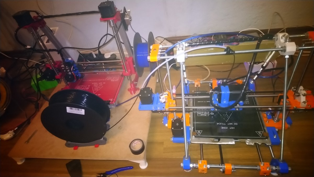
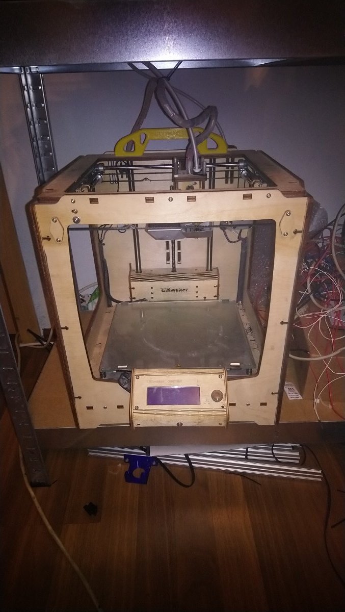
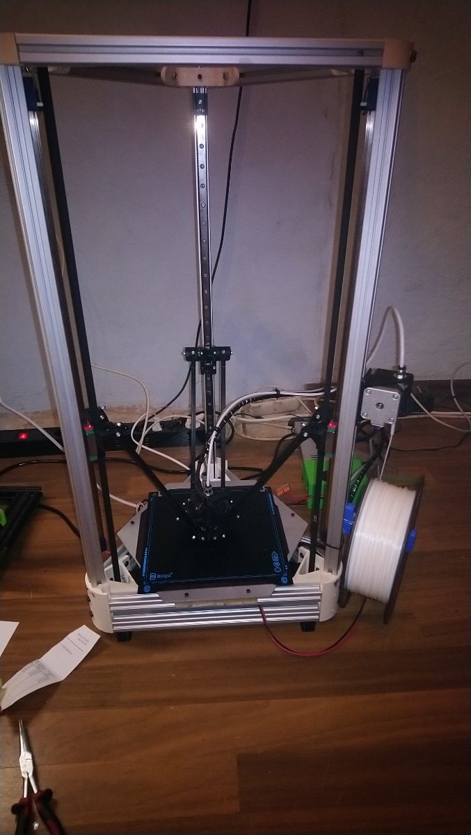
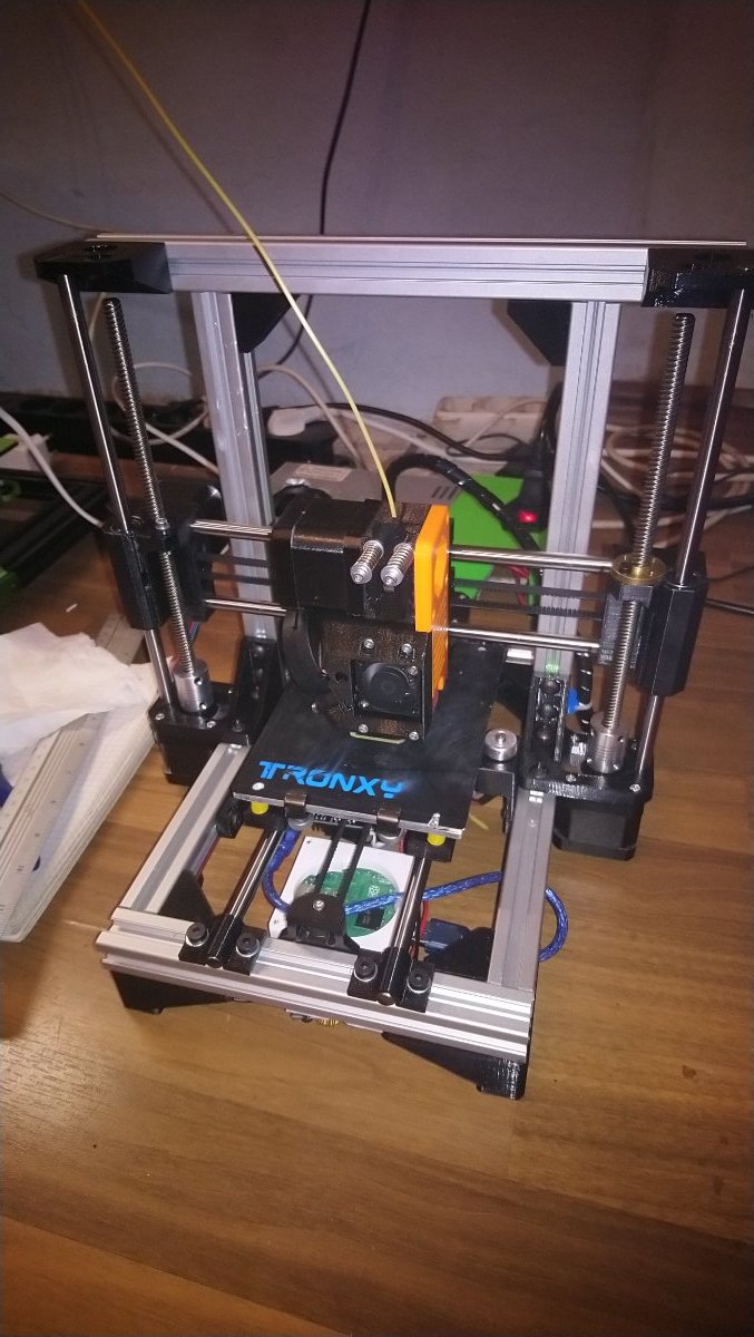
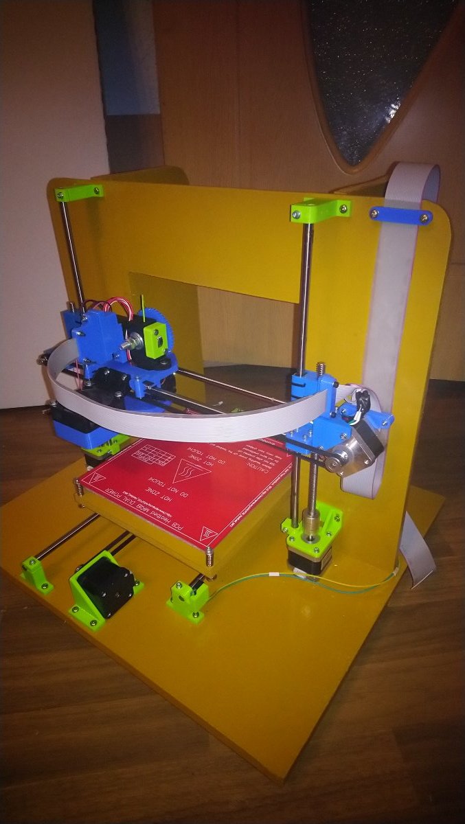
These are some of the machines I have built. I know full well they are not perfect but I love them all.
7 points
-
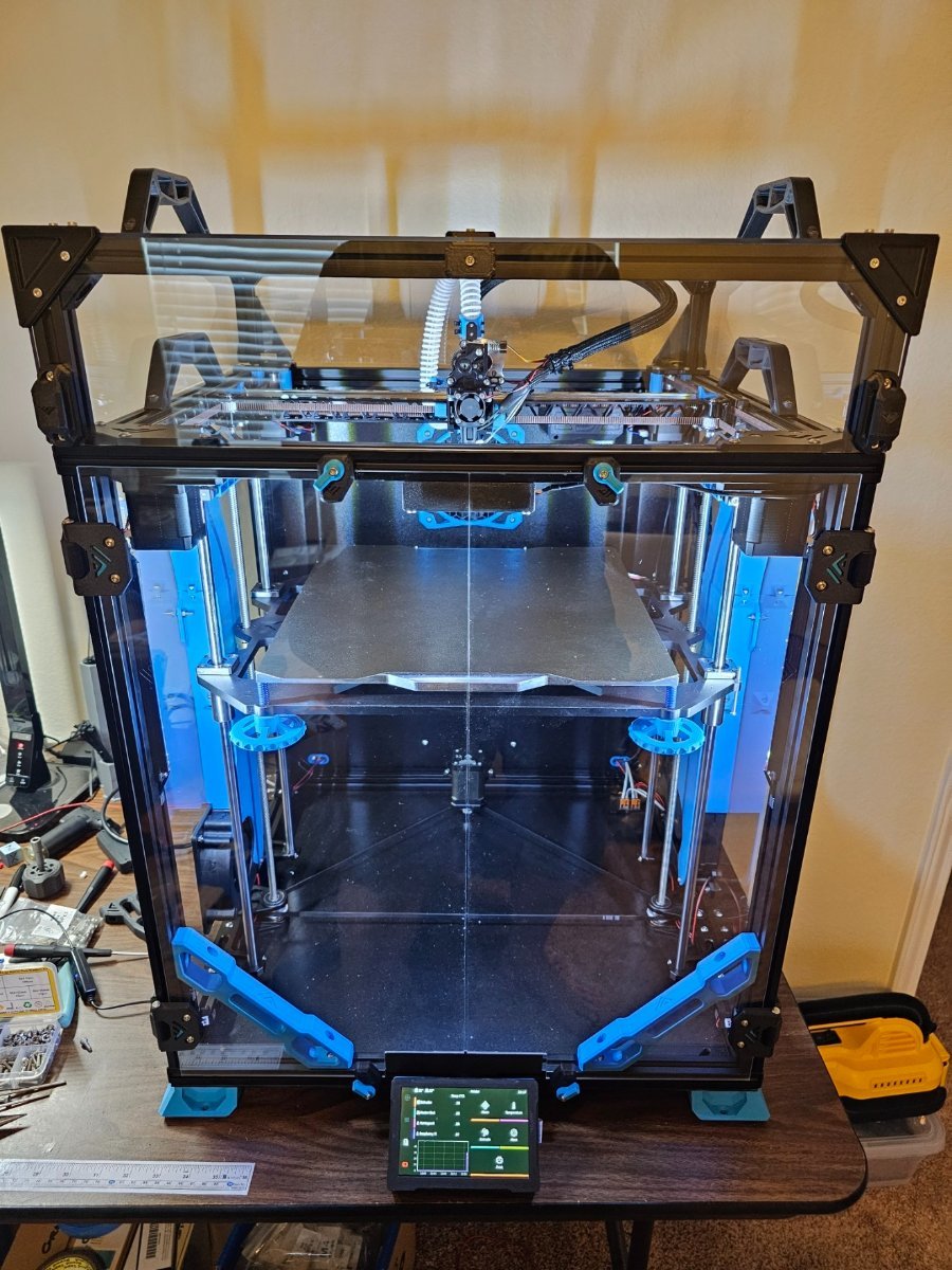
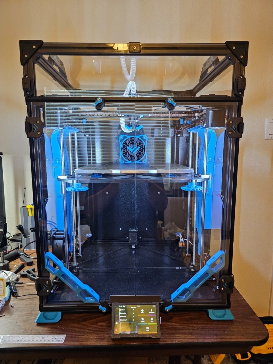
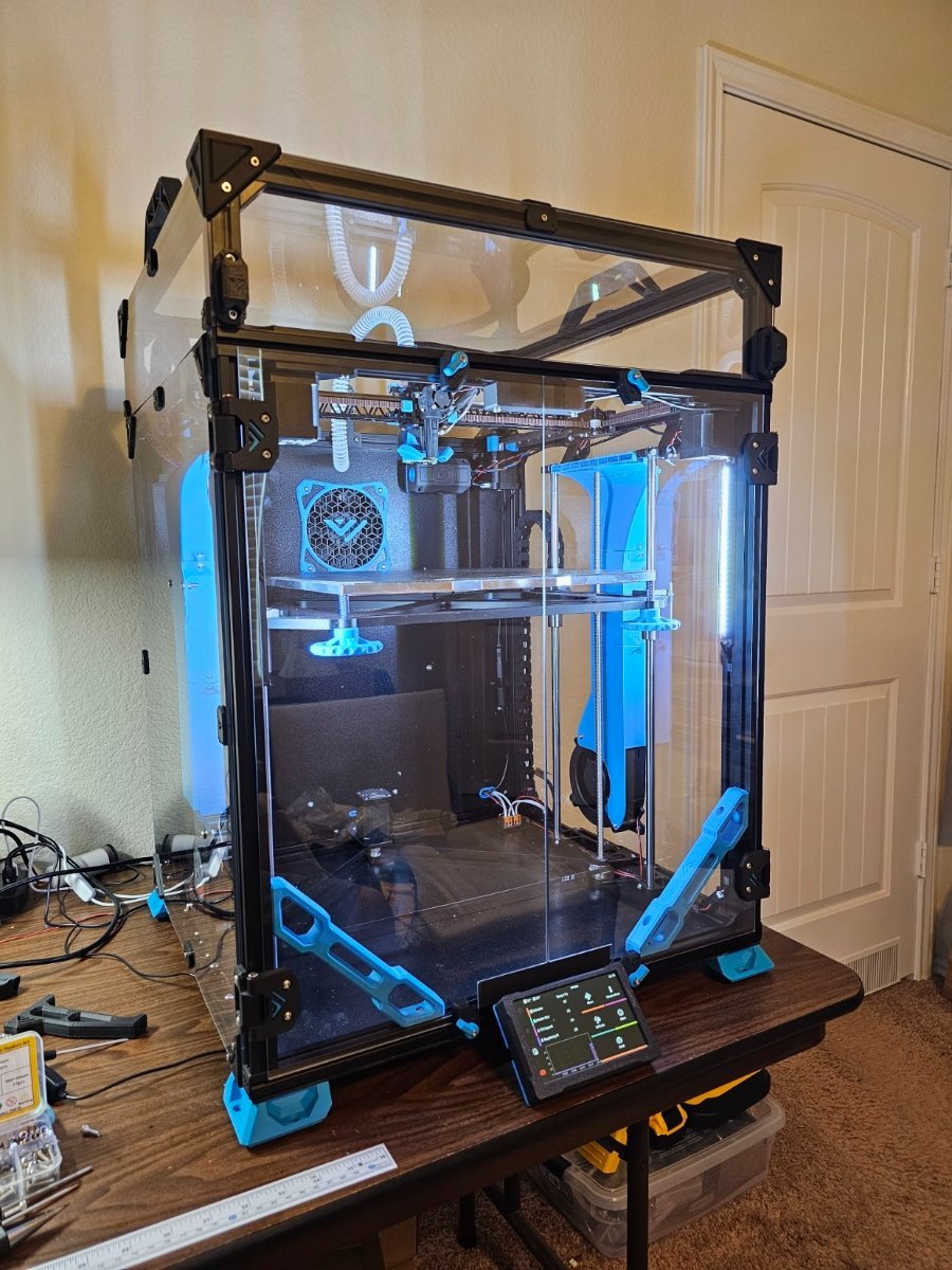
And now for the front... I'm literally done but want to move it into my office before printing the first print so, I gotta wait for my buddy to get home to help me move it over. It's not that I can't lift it myself, although it's probably about 80 lbs, it's that I don't want to risk dropping anything. So here it is, powered on and ready. All panels, fans, lights camera, you name it.
7 points
-
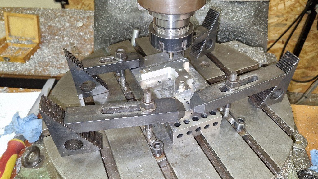
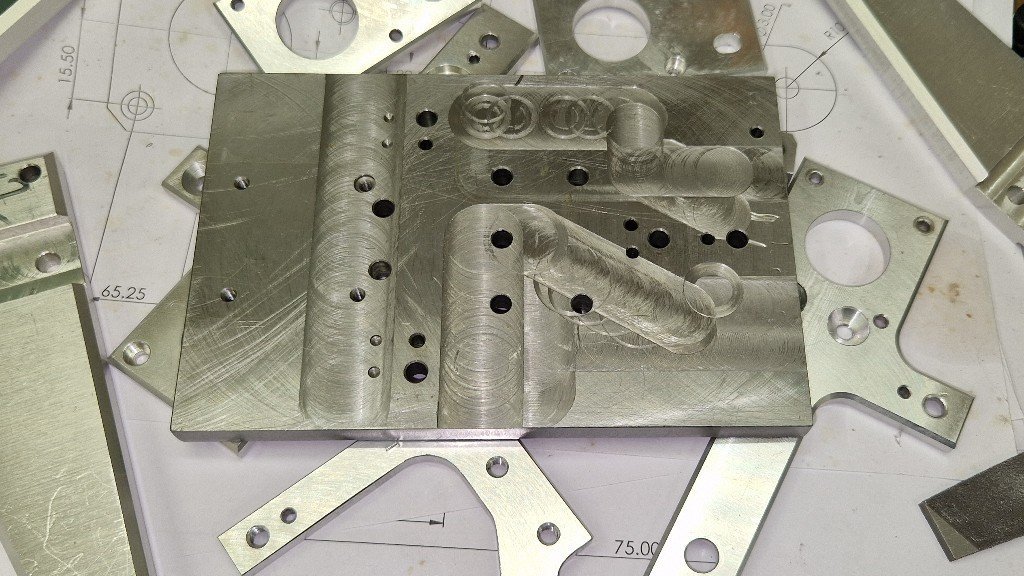
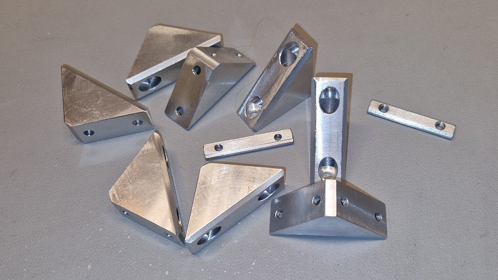
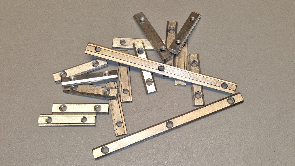
The 0.2, still unfinished, but functional. Protective sheets are still there on the acrylic panels. I don't like the hinges on the right side, and about to mirror everything... This printer wouldn't exist without the bed slinger that was built for this purpose, and for this purpose only. The "Super Tornado". Kept the frame, the bed, and the 3 wheel X carriage. Everything else was properly redesigned and made. It will be scraped or repurposed after the two Vorons (0.2 and 2.4/350) are operational. An early design : The Y carriage, reinforced. 4 wheels are on eccentrics, because assuming that 3 wheels can be inline is pure nonsense. Adjustments require a special tool : The Z carriages. Machined from 8 mm thick aluminium (reduced to 6 mm). Double eccentrics for wheel adjustments. Machining the carriages... First, had to design and machine a jig... All corners are reinforced. No cast aluminium rubish. Machined ! So I am sure the corners are all real 90° (as accurate as the machine that made them). Also made some multithreaded M5 T nuts", from mild steel. Then, they were zinc electroplated. Frame/Z axis junctions. Machined for a tight fit (AKA machinist fit), at true right angle. Z motion. One motor, 2:1 reduction. The two leadscrews are suspended on a pair of preloaded deep groove bearings. Y axis ; the tensioner : The motor : More to come, before the Voron 0.2 mods...
7 points
-
Thanks to @Meishu Started thread on suggestion of @RopusLongus. Thank you
7 points
-
Hi, I just want to share how I installed Klipper, Moonraker and fluidd on my Orange PIs. 1. Download Armbian (I use the debian/bullseye) for your board from here: https://www.armbian.com/download/ 2. Write the image to a 'good' SD card. 3. When booting for the first time, you are asked to create a new root password and then a user. I always created a user 'pi' not to run into any problems, as the Klipper documentation is written for a user 'pi'. 4. Before logging out and log in as 'pi' I always run 'apt-get update' followed by 'apt-get upgrade'. After that is done, on a board with eMMC you could now copy the OS to the eMMC with 'nand-sata-install'. 5. Now logged in as user 'pi' KIAUH can be installed. Just follow the instructions from here: https://github.com/th33xitus/kiauh 6. Now Klipper, Moonraker, Mainsail/fluidd can be installed.7 points
-
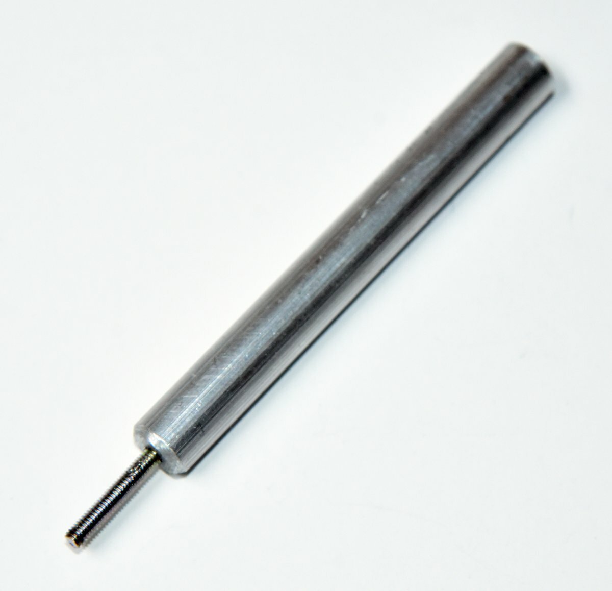
The missing tool... I have worked with threaded metal inserts for years. The one thing I have found indispensable is a simple to make tool that allows you to pull inserts out of plastic and help with getting them started to install. The one shown is for 3mm inserts. I used an aluminum rod, drilled and tapped a hole on the end, and cut the head off a 3mm screw to put in the end. I thread the insert on a few turns and place the insert at the hole to be "threaded". I use a old Weller soldering iron with a conical tip, and finally the non-blade end of a large hobby knife (1/2" round flat surface) to flatten out any plastic ridge formed. I also heat up inserts and then use the tool to pull out ones to recycle (I know, cheap parts but I don't like to waste them).
7 points
-
Hi all, I'm Kris from KB3D, you may recognize us from the Voron Discord's vendor section - or maybe you're already one of our great customers! Born to support open-source hardware projects, we have been building our Voron catalog with high-quality parts at competitive pricing. Our entire catalog is in-stock at our warehouse in NE Ohio with order handling times of less than 24 hours. We are the North American home of Linneo wire harnesses and currently offer products from E3D, Bondtech, Slice Engineering, LDO Motors, Gates, IWISS, and many others in addition to our own in-house manufactured items. There are many ways to get in touch with us, but I wanted to open a line of communication here at TeamFDM as well! Kris @ KB3D https://kb-3d.com6 points
-
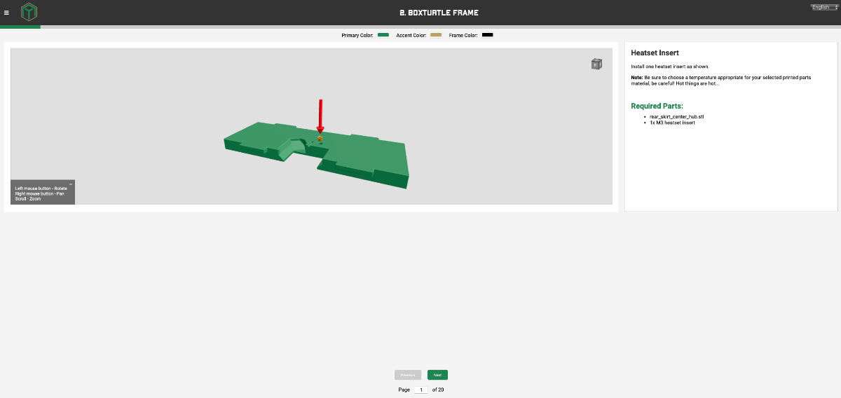
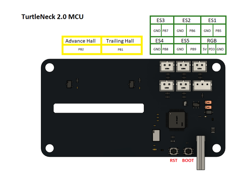
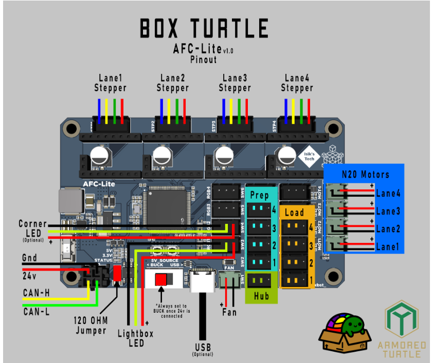
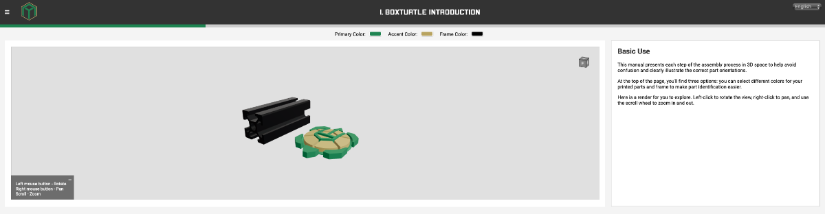
Well, I bit the bullet @7milesup. Here is the build diary of the Box Turtle AMS style Filament changer from Armored turtle. The Preamble: Decided on a Green and Gold (Actually it is yellow) colour scheme - I am in Australia after all! Opened the stl file configurator from the Build manual website, which gathers the stl's you need and packs it in a zip file for downloading. This is one of the things I really like - no sifting through directories of stl's to find what you need to print. Answer a few questions and away you go. I also like the way the build manual is compiled. (as is my habit, I read through the manual before starting the project). Though it is web based, and not in downloadable pdf form, it works. Instructions are clear and most of all, they are accompanied by a 3d-rotatable picture of the step you are at - Love it! No more twisting of necks to see exactly what needs to be done - just rotate the image. In addition to the Box Turtle stl's, you'll need to decide on an extruder sync sensor (Toolhead Buffer). I chose the Turtleneck buffer system as I have the Belay sensor on the Tradrack and wanted to build something different. The turtleneck has been advanced to the turtleneck 2, but that requires a dedicated PCB (Turtleneck2 MCU). (I may just order that - see how it goes). This can be ordered from Isik's Tech Site, as well as the dedicated ACF board. In addition to the toolhead buffers, a filament sensor is needed in the toolhead. I choose the integrated one's for the stealth burner from the ERCF project, as all the printers already have these toolhead installed. The other option is the Armoredturtle Filatector in-line sensor. (So spoiled for choice) The Build: 1. Box Turtle introduction. The introduction goes through the print settings, explanation of instructions, assembly queues and links to the stl-generator, GitHub and discord. It also discusses part selection and this is handy when it comes to using the stl-generator. I would suggest printing the "Calibration Fidget" in order to determine your printer tolerances, especially if you will be using two seperate printers to print the parts. (I generally load the bigger of the printers with the main colour parts and another smaller printer with the accent colour parts). The printers used on this build was the VZBot 330 for the main coloured parts, The Trident 300, for the accents and the V0.2 for the clear, opaque and TPU parts. Next: 2. Boxturtle Frame
6 points
-
Nothing really changing on this--it's getting occasional use lately. But a fun little anecdote. My daughter needed a prop for a book report project in school. The book was The Boys In The Boat and she wanted a racing shell model as a display. I managed to find one on Printables; a single-seat modern one, but it gets the idea across. I made sure to use the V0 that she built and told her to mention that fact. The report went well (she got an A. ) and she said the teacher mentioned that was the first time anyone used a 3d printed prop. She later told me she also got extra credit after telling the teach that she built the printer used to produce the boat model.6 points
-
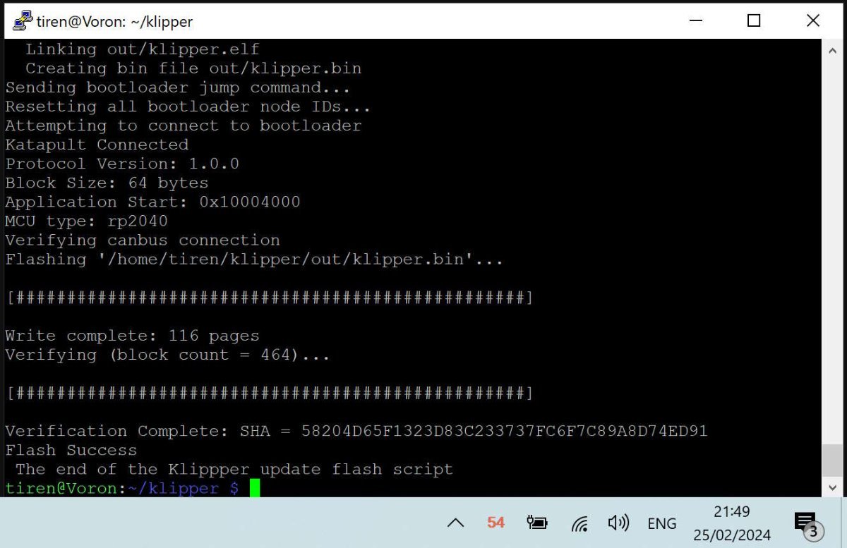
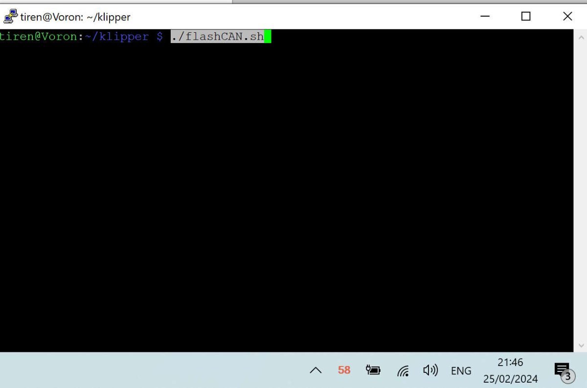
I have been converting my Voron 2.4 from many-cables-to-the-toolhead, into a single can-cable (4 wires) system. Even though I saw here that many people really did not like the CAN bus on their printers, mainly because it was new and unknown. The problem of the web is and always has been, that you never hear the 'satisfied' people. Only the very unhappy, the very happy and the sales-people. I hope this script will make it easier for some to make the step to the 'new'. I have never been afraid of new things. The problem was finding a way to find the set up I needed. From one came the other and what happened was, that I was able to combine information from a few sites / github pages I visited, and was able to write a simple script that did all the work. Actually very much like every software / game in the pre-windows 95 era, came with its own 'set-up' disk, with config.bat / setup.bat files. As long as I do not have a Klipper '95, I think this script will do for me. I tested it, and it takes 3 to 4 minutes to update the mainboard and toolhead PCB. Faster than 5 minutes I heard mentioned before. I will paste the script down here, with all the comments and the instructions. and attach as an attachment also. If there is a better way, let me know. It is information gathered mainly from Esoterical's guide. You will need information from this guide to set up your own script. -------------------------------- SCRIPT flashCAN.sh ------------------------------------------------------------------ #!/bin/bash ### without the extensive documentation and work of Esoterical, this would never have been possible. ### Besides Esoterical, this script builds standing on shoulders of: ### Eddie the engineer. https://www.youtube.com/watch?v=1P4UrJxChL8 Thanks! ### cruiten https://github.com/cruiten/Voron-Related/blob/main/CANbus/Documentation/SB2040_CAN/flash_klipper_script.md Thanks! ### uses # https://docs.kernel.org/kbuild/kconfig.html KCONFIG_CONFIG is used to define an alternative config file... ### to define a separate config file for mainboard (eg Octopus) or for a canbus toolhead PCB. For both cases one for katapult and one for klipper. ### the make menuconfig commands use the Esoterical github provided 'mainboard/common_hardware and toolhead_flashing/common_hardware maps provided image options ### https://canbus.esoterical.online/mainboard_flashing/common_hardware.html ### https://canbus.esoterical.online/toolhead_flashing/common_hardware.html ### HOW TO USE: Follow Esotericals guide, starting at the begin: https://canbus.esoterical.online/Getting_Started.html ### it will lead you through setting up a can network on your Klipper running os. ### I skipped the part about dedicated can_boards, and continued with the klipper USB 2 CAN bridge provided by my mainboard: https://canbus.esoterical.online/mainboard_flashing ### will go through flashing your mainboard for CAN. go through EVERY step. and DO NOT skip the STOP warnings. This will install katapult. USB2CANbus bridge ### afterwards it will assist you through flashing your toolhead: https://canbus.esoterical.online/toolhead_flashing ### like with the mainboard, you will install katapult and then the klipper can interface on it. ### when you are finished, you get advise on how to finish it: https://canbus.esoterical.online/Final_Steps.html ## You are happy and you see an update from Klipper in mainsail. You push the update button and your whole system is unaccessable, ## because your hardware is no more up to date with the latest klipper... ## in that case you can follow the "so you clicked the update button???" : https://canbus.esoterical.online/Updating.html ## because I did not want to go through the same repetitive steps, I made this below script. ## If I did not think this would be faster than the 5 minute update teamfdm.com @mvdveer needs to update his printers, I would have kept it to myself. ## -------------------------------------------------------- HOW TO USE ----------------------------------------------------------- ## save this document and copy to your klipper system into the /klipper directory. ## give it a name (eg. flashCAN.sh) ## ssh into your system. go to your klipper directory and run the command: sudo chmod +x flashCAN.sh ## now you can run the script by typing the following command in ssh ## ~/klipper/flashCAN.sh ## make sure to fill in your OWN values for ## - usb-katapult_your_mainboard_usb_id ## - yourmainboarduuid ## - yourtoolheaduuid # these are values for me! # yourmainboardUUID=403544310df5 # katapult_your_mainboard_usb_id = usb-katapult_stm32f446xx_200035000851313133353932-if00 # yourtoolheaduuid =21c36fa97c26 ## while installing CAN the first time, note your usb-katapult-mainboard-usb-id, mainboard UUID, toolhead UUID. ## or if you have a functioning CAN network, run ~/klippy-env/bin/python ~/klipper/scripts/canbus_query.py can0 to see a list of installed CAN devices. ## the UUID for mainboard and toolhead you need to put in your printer.cfg file, so you can retrieve it from there. ## But the USB serial ID you have to obtain after you put the mainboard into katapult boot flash mode (STEP 2 A below). ## after the command python3 ~/katapult/scripts/flashtool.py -i can0 -u yourmainboarduuid -r ## you will need to type: "ls /dev/serial/by-id" and it will give you your USB serial ID. ## once you have run through this script, comment out (put a # in front of the line) the line which has the "make menuconfig" in it. ## and the next time you have a klipper update that breaks your CAN, all you have to do, is to run this script once. #-------------------------------------FINAL WORDS-------------------------------------------------- # this script is for me and my set up. # HARDWARE # Raspberry Pi 4B, 8mb # Voron 2.4, 350 # Octopus Pro mainboard # SB2209 (RP2040) Big Tree Tech 2 part Toolhead PCB # Cartographer 3D Eddy Probe in CAN mode # with built in accelerometer / resonance tester # The Octopus functions as a CAN bridge. Cartographer 3D is connected to The SB2209 (RP2040). # The CAN bus is terminated at the Cartographer 3D probe. # SOFTWARE: # OS: Raspbian GNU/Linux 11 (bullseye) # Distro: MainsailOS 1.2.1 (bullseye) # klipper: v0.12.0-114-ga77d0790 # if you are not using this script on my system then anything can happen which I am not responsible for. echo "STEP 1 - UPDATE KATAPULT FROM GIT if needed" test -e ~/katapult && (cd ~/katapult && git pull) || (cd ~ && git clone https://github.com/Arksine/katapult) ; cd ~ echo "STEP 2a - FLASH MAINBOARD KATAPULT so we can flash it easily" cd ~/katapult make clean KCONFIG_CONFIG=config.mainboardKatapult # cleans old files make menuconfig KCONFIG_CONFIG=config.mainboardKatapult # this can be commented out for automation AFTER you have filled out correct fields for your card. or leave it in to have some control make KCONFIG_CONFIG=config.mainboardKatapult # this creates a deploy.bin python3 ~/katapult/scripts/flashtool.py -i can0 -u yourmainboarduuid -r # puts mainboard in katapult flash mode python3 ~/katapult/scripts/flashtool.py -f ~/katapult/out/deployer.bin -d /dev/serial/by-id/usb-katapult_your_mainboard_usb_id # flashes katapult to mainboard echo "STEP 2b - FLASH MAINBOARD so it works as a CAN BRIDGE, over KATAPULT" cd ~/klipper make clean KCONFIG_CONFIG=config.mainboardUSB2CANbb # cleans old files make menuconfig KCONFIG_CONFIG=config.mainboardUSB2CANbb # configuration for klipper-U2CBB. comment this line for automation make KCONFIG_CONFIG=config.mainboardUSB2CANbb # this creates klipper.bin sudo service klipper stop # mainboard still in katapult forced flash mode. so feel free to flash klipper can bridge on it! python3 ~/katapult/scripts/flashtool.py -f ~/klipper/out/klipper.bin -d /dev/serial/by-id/usb-katapult_yourmainboardusbid # flashes klipper-U2CBB to MAINBOARD sudo service klipper start echo "STEP 3a UPDATE TOOLHEAD KATAPULT so we can flash it easily" cd ~/katapult make clean KCONFIG_CONFIG=config.toolheadKatapult # clean old files make menuconfig KCONFIG_CONFIG=config.toolheadKatapult # comment out for full automation after once filled out! make KCONFIG_CONFIG=config.toolheadKatapult # build katapult deployer.bin python3 ~/katapult/scripts/flashtool.py -i can0 -u yourtoolheaduuid -r # put toolhead board into katapult flash mode python3 ~/katapult/scripts/flashtool.py -i can0 -u yourtoolheaduuid -f ~/katapult/out/deployer.bin # flash the katapult binary echo "STEP 3b UPDATING TOOLHEAD KLIPPER over KATAPULT" cd ~/klipper make clean KCONFIG_CONFIG=config.toolheadKlipper make menuconfig KCONFIG_CONFIG=config.toolheadKlipper make KCONFIG_CONFIG=config.toolheadKlipper sudo service klipper stop python3 ~/katapult/scripts/flashtool.py -i can0 -u yourtoolheaduuid -f ~/klipper/out/klipper.bin sudo service klipper start echo " The Klippper update flash script has finished. Hopefully all is working again :-)" flashCAN.sh
6 points
-
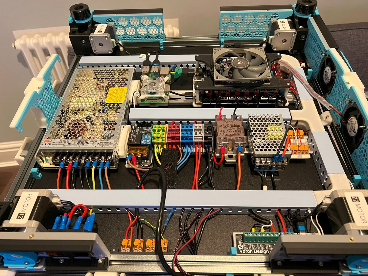
The Final Electronics Bay...
6 points
-
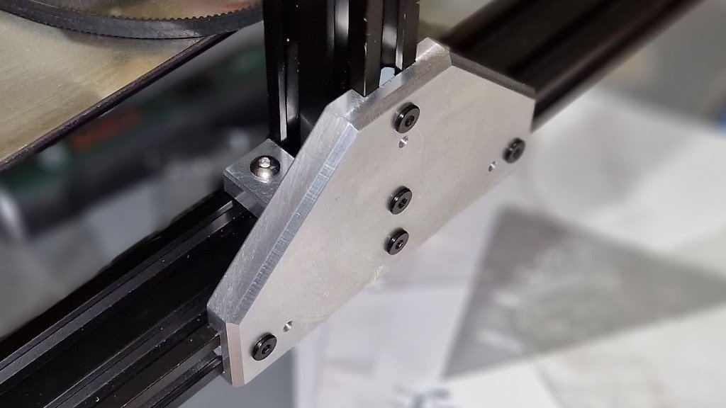
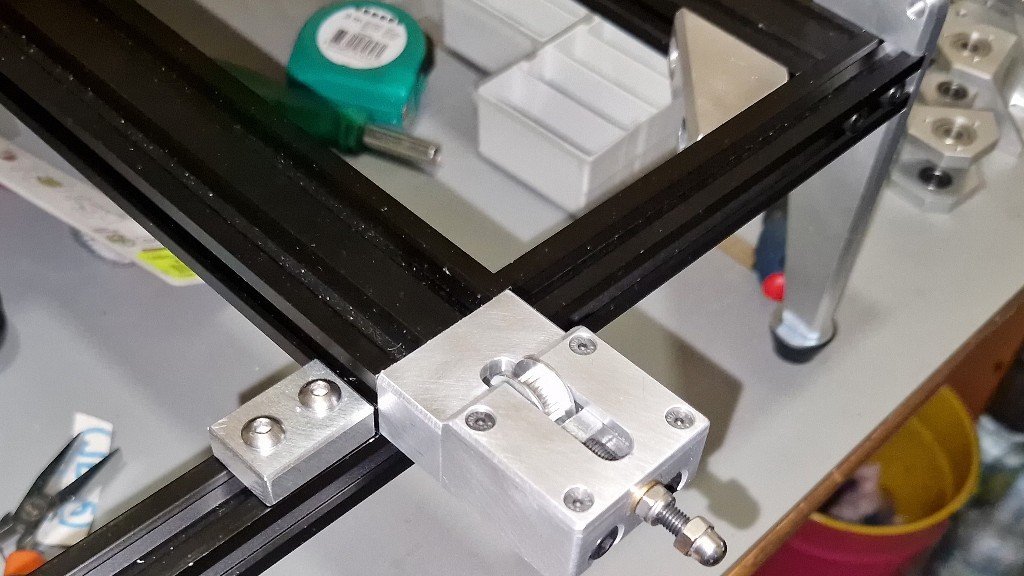
Made some good progress and as hoped there is no gantry motion when force is applied so gantry sag should be solved. Next is to wiring the electronics and get it moving
6 points
-
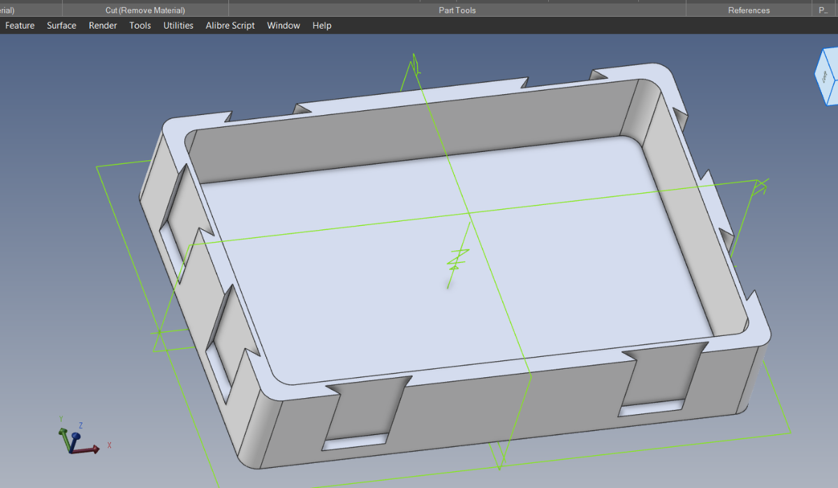
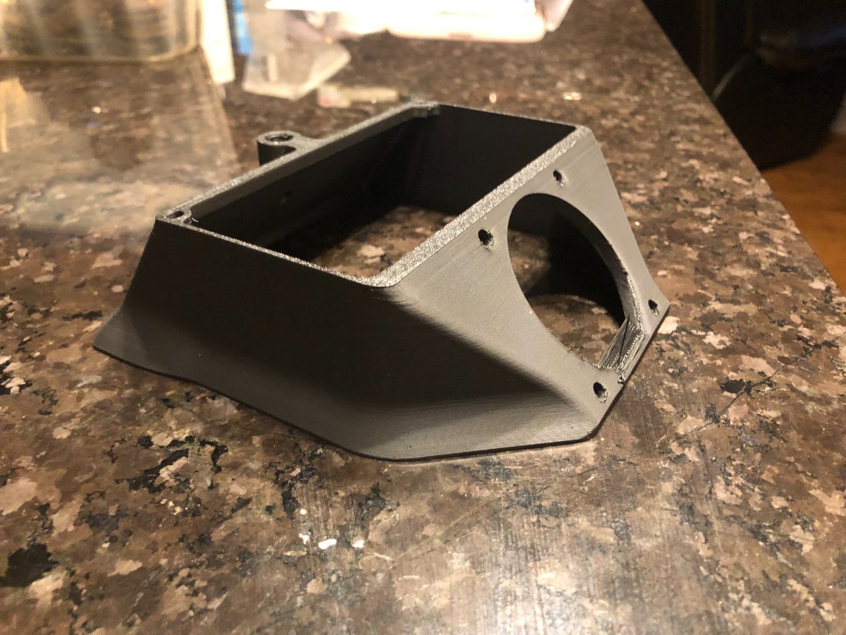
With ABS, some designs are really tough to produce without warping. In your specific case, it's the long, uninterrupted extrude lines. When a material cools it contracts at a rate the is usually expressed in unit of length, per unit of length per degree temp. So, the longer the object is, the more it contracts per degree of temp change. Shorter sections will result in reduced forces. With a design like yours, in order to reduce the magnitude of warping, i might change the model to look something like this. I added some vertical flutes to break up the long, strait lines. For ABS specifically, the coefficient of linear expansion is .00005 inches, per inch, per degree. So, a 5" long plastic wire/extrusion that cools from 230c to 30c will try to be .095" shorter after cooling. Since it's glued to the previous layer and can't contract, it will just create a force. Each layer will cool and attempt to contract the same amount, after being layed down on a previous layer that is already producing stress. Each layer will add its own warping stress to that all of the previous layers. So, for this part: You could reduce the warping issues with some changes like this. It may not eliminate the issue altogether, it would reduce the magnitude of the problem. Perhaps that, in combination with higher chamber temps, and some brims, you might get the results you need: If aesthetics are of little concern, or if the intended use allows for it, even more severe changes could eliminate the warping problem. An example: The higher the long, strait extrude lines are above the build plate, the more leverage (arm) they have, to further magnify the warping forces. So, breaking up those long lines on the higher portions is more important than those lower on the part. It's one of the reasons that parts like yours are so difficult to keep from warping with ABS, and parts like the one below are so easy. With a circular part, contraction forces from cooling only create a hoop stress that tends to reduce the parts diameter, and has little leverage with which to pull up the edges of the base with.
6 points
-
Going to be building a Salad Fork. I want a small printer to compliment my Big Chungus 350 2.4. After researching my small printer options I settled for the Salad Fork, a deliciously overengineered small printer. I did a pretty standardish black base and blue accent on my 2.4, so for this one I want to be a little more crazy. Here's the color scheme I am going to be going for: Blue frame, white base, blue accents. Going to be a little while before I start on this build, I am preordering through Fabreeko as they seem to some fantastic kits at a fantastic price. It doesn't look like it will be shipping for 45 days or so though. I've got white KVP ABS on order and am going to start printing out parts next week. Here are some plans that are going to make this more interesting: Will be running canbus (Default in the kit) Will be running boop (because once you go TAP you never go back) Will be running an lgx lite extruder, because I like that extruder a lot on my 2.4. Will be running a Revo, or Rapido. Not quite decided yet. Will start updating the build log as things go.
6 points
-
I have a 300mm from chowthink, came in a set of two with other being regular powdercoated pei, both double sided. At the time, around xmas, that set was regularly discounted to 30 or so on amazon . bought for the pei but figured was worth trying the pet cf basically for free. it works, though i haven't used it with ABS that i can recall - its max temp is something like 80. But I've used it with PLA/Petg. as with any smooth surface, your first layer squish quality is going to be very evident. Textured pei hides some sins there, and seeing infill lines bugs me aesthetically I wouldn't be happy with your example pic for instance. but it's a very good set, had a buddy buy another one for the cr10->sw conversion i did for him, and that's been solid too. I've used a couple dozen spring steel surfaces across a half dozen printers including my v0, switchwire, and v2. From $10 no name amazon sheets to the vaunted "energetic" (which I feel are overrated, they degrade quickly). By far the best I've used is an LDO textured on the switchwire. Sticks well, and is very resistant to damage and degradation. If Amazon still had the 300mm in stock I'd buy one and demote the chowthink to backup on the v2. Last thought is, when all else fails , pull out the Elmer's purple glue sticks. I resisted that method for two years. Figured glue or hairspray or slurry or anything was cheating and meant something was inherently wrong with my build or tuning. Nah. Elmers absolutely saved my v0 in terms or usefulness. I had gone through 5 or 6 sheets on the v0 alone trying to find something that would stick- even pla was troublesome - and this is with 0.05 flatness and zeroclick mesh. After a coating of purple not only does it stick reliably, garbage filaments I thought were completely useless became just as good as expensive filament. Tronxy ABS? Sure, why not. I don't even have to clean it, and only reapply some every couple dozen prints. Now the v0 is my go to. the SW and V2 didn't have the lifting issues nearly as much, only showing up with a difficult part like a large box, or a unibody v0.1 hat. But where in the oast i had to use large brims to tame those parts, elmers lets me skip the brim entirely and print any shape that takes my fancy. My custom v2 skirts would never have printed without it.6 points
-
Whooo - Hoooo. Persistence paid off! Finally can put an end to the ERCF saga - I have conquered ERCF. Now I can end this saga. 4 color multiprint: IMG_4412.mov Lessons learned: 1. Be meticulous in EVERY ASPECT - Build, Calibration, Settings 2. Be anal in the build 3. Do not take shortcuts 4. Read the manual - not once, not twice, not thrice - READ the MANUAL! 5. Follow the calibration steps to the LETTER - Follow the manual word for word 6. Take your time to get the ideal tip formation 7. Ensure you have a well build printer to start off with. 8. Remember to enter your values in your slicer profile. 9. Did I say READ THE MANUAL and FOLLOW it meticulously? Will I ever use this? Who knows? It was a challenge and I am happy that I took it on and managed to successfully build, calibrate and implement it. It was fun. Onto the next project.
6 points
-
@atrushing @Chuck_Snow @Buurman This forum as always is so helpful turns out what I was adjusting for pressure advance was the smooth time, pressure advance was still commented DUH! Adjusted the seam location to corners and this was the result - the seam is gone!
6 points
-
Dusted off the Trident 250mm Formbot kit and laid out the parts on the build table. You're not building ANOTHER one!, she said rolling her eyes. But honey - its the Trident build - remember Poseidon or Neptune - powerful Gods all had the three thronged spear. I gotta have one too. Yeah but you're not in Atlantis - you're in sunny Oz! What can I say but Trident it is. Build plan: (I know it will change as I go along this three pronged journey) Color Scheme: Main: Grey Accent: Silver and Light blue (Black for electronics bay - cause if the magic smoke happens everything is already black) @Buurman - tested the silver for strength as you suggested - seems to be holding up as good as the grey Filament: eSun ABS+ (Hotend 245, Bed 110 Chamber 42) Printed Parts printed on Voron 2.4r2, - 40% infill, 0.4width forced, speed 100mm/s, acceleration: 4000mm/s Hardware: 1. Formbot Kit as a basis (Frame, hardware, wiring, electronics, etc) BTT Octopus v1.1 board, TMC2209 stepper drivers included as well as a Bigtreetech Mini 12864 v1.0 LCD 2. Voron TAP with 5V PCB and optical sensor: (https://github.com/VoronDesign/Voron-Tap) 3. Sexbolt Z endstop: (https://github.com/hartk1213/MISC/blob/main/Voron Mods/Voron 2/2.4/Voron2.4_SexBolt_ZEndstop/STLs/TridentSexBolt.stl) 4. Pin Mods for AB Drives and XY joints:(https://github.com/VoronDesign/VoronUsers/tree/master/printer_mods/hartk1213/Voron2.4_Trident_Pins_Mod) 5. Ramalama2 front idler mod: (https://github.com/Ramalama2/Voron-2-Mods/tree/main/Front_Idlers) 5. Door Hinge mod: (https://github.com/VoronDesign/VoronUsers/tree/master/printer_mods/randell/Door_Hinges) 6. Nevermore Carbon Filter: (https://github.com/nevermore3d/Nevermore_Micro/tree/master/V5_Duo) 7. Logitech C922 camera mount (https://github.com/VoronDesign/VoronUsers/tree/master/printer_mods/Iakabos/C920_mount) 8. Inverted Electronics mount (https://github.com/VoronDesign/VoronUsers/tree/master/printer_mods/LoganFraser/TridentInvertedElectronics) 9. Raspi Pi 4, 4GB 10. BTT PiTFT50 with Klipperscreen 11. Revo Voron Hotend Mods considered but not yet included: (will see when I get to that part of the build ) 1. Internal Spoolholder / Horseshoe spoolholder - don't think this will fit inside a 250mm build: (https://github.com/VoronDesign/VoronUsers/tree/master/printer_mods/LoganFraser/HorseshoeSpoolHolder) 2...... whatever pops up along the way!! No doubt @claudermilk will have some great suggestions. I know he is planning 3 mods on his already finished Trident Unpacking the kit : Well packaged and surprised at what was included. BTT Octopus, Moons Motored, Dragon HF hotend. Rails look OK, but will have to clean and see how they perform
6 points

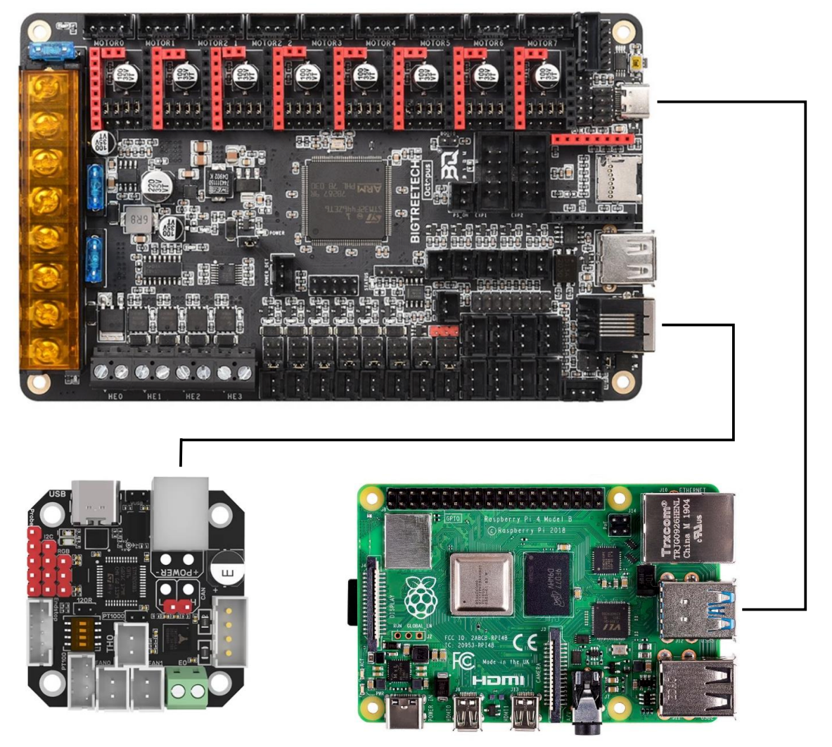

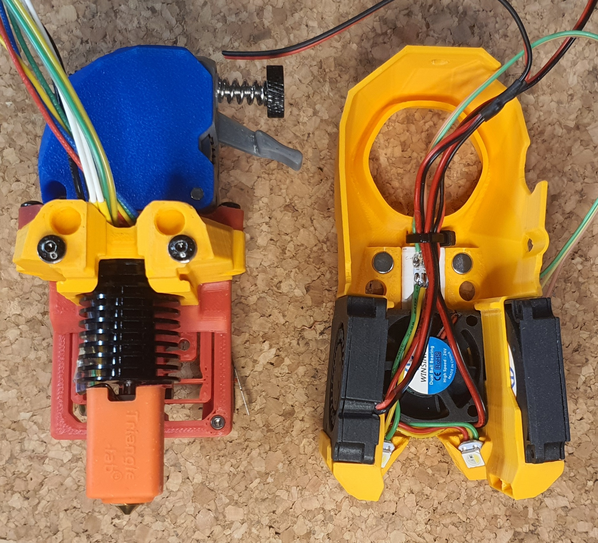
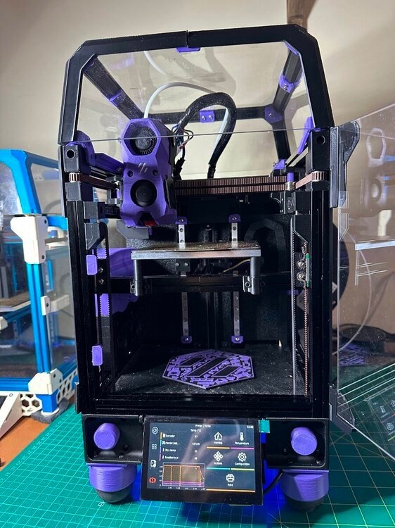
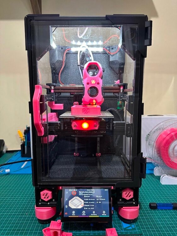
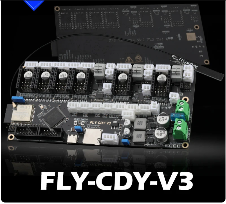
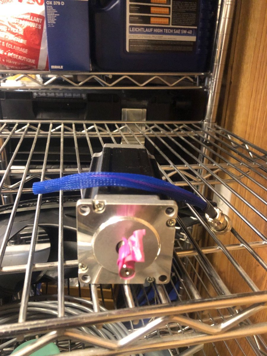
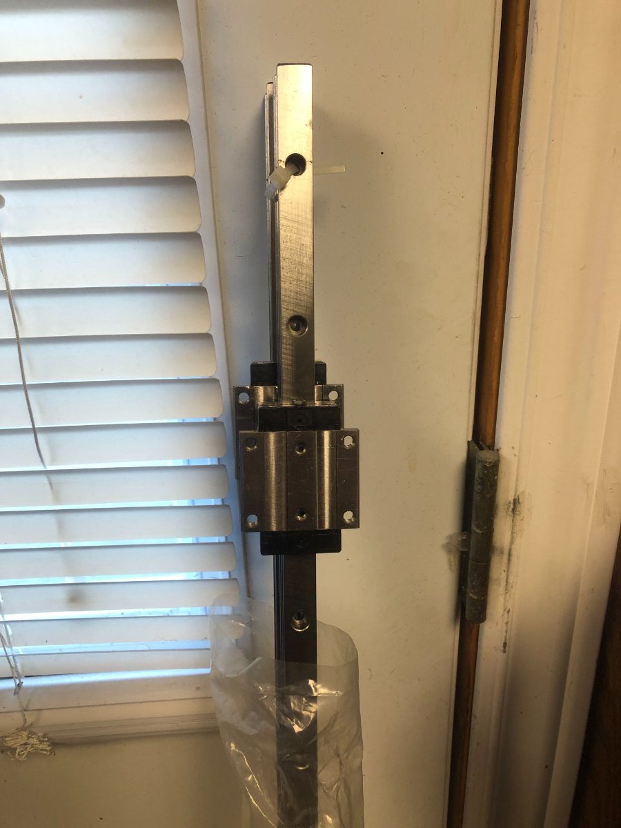
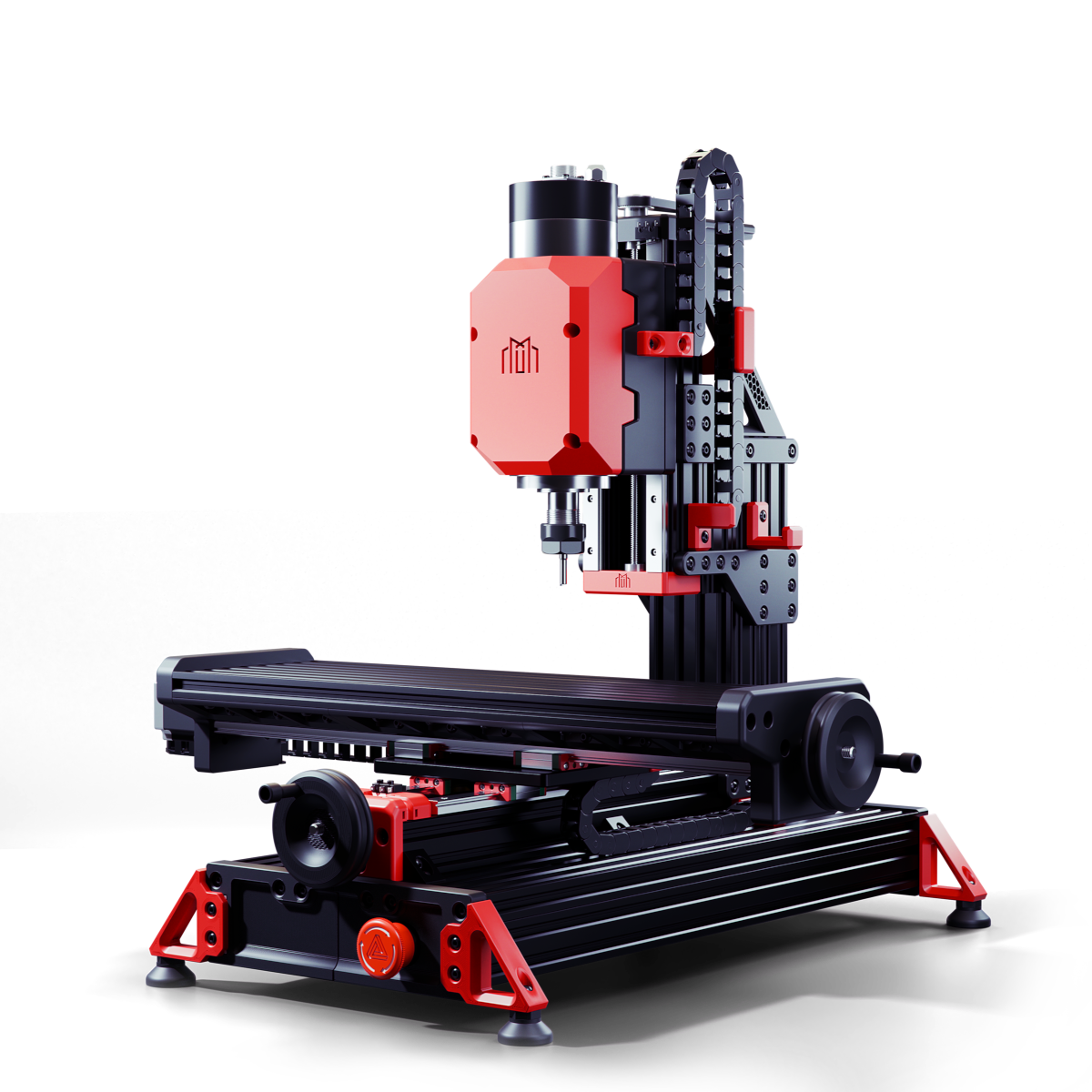
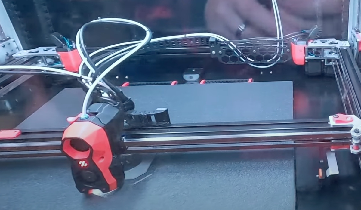
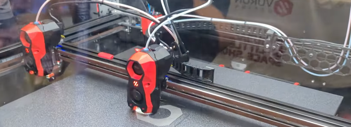
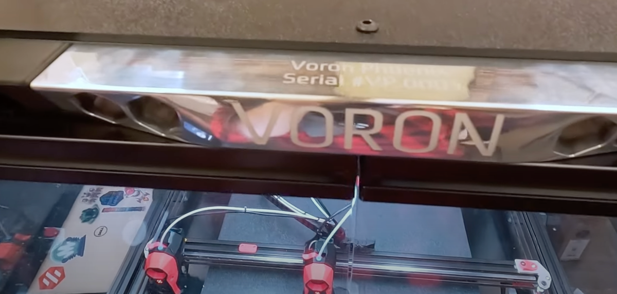

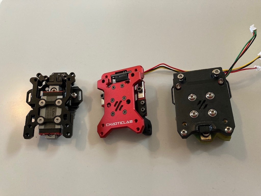
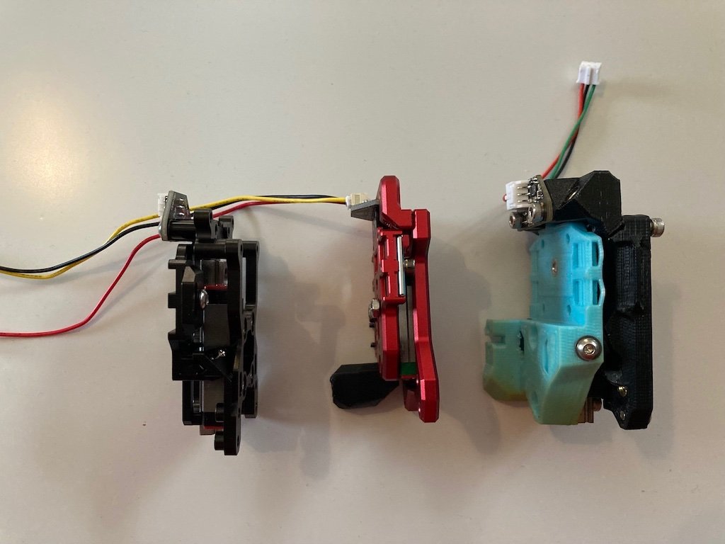
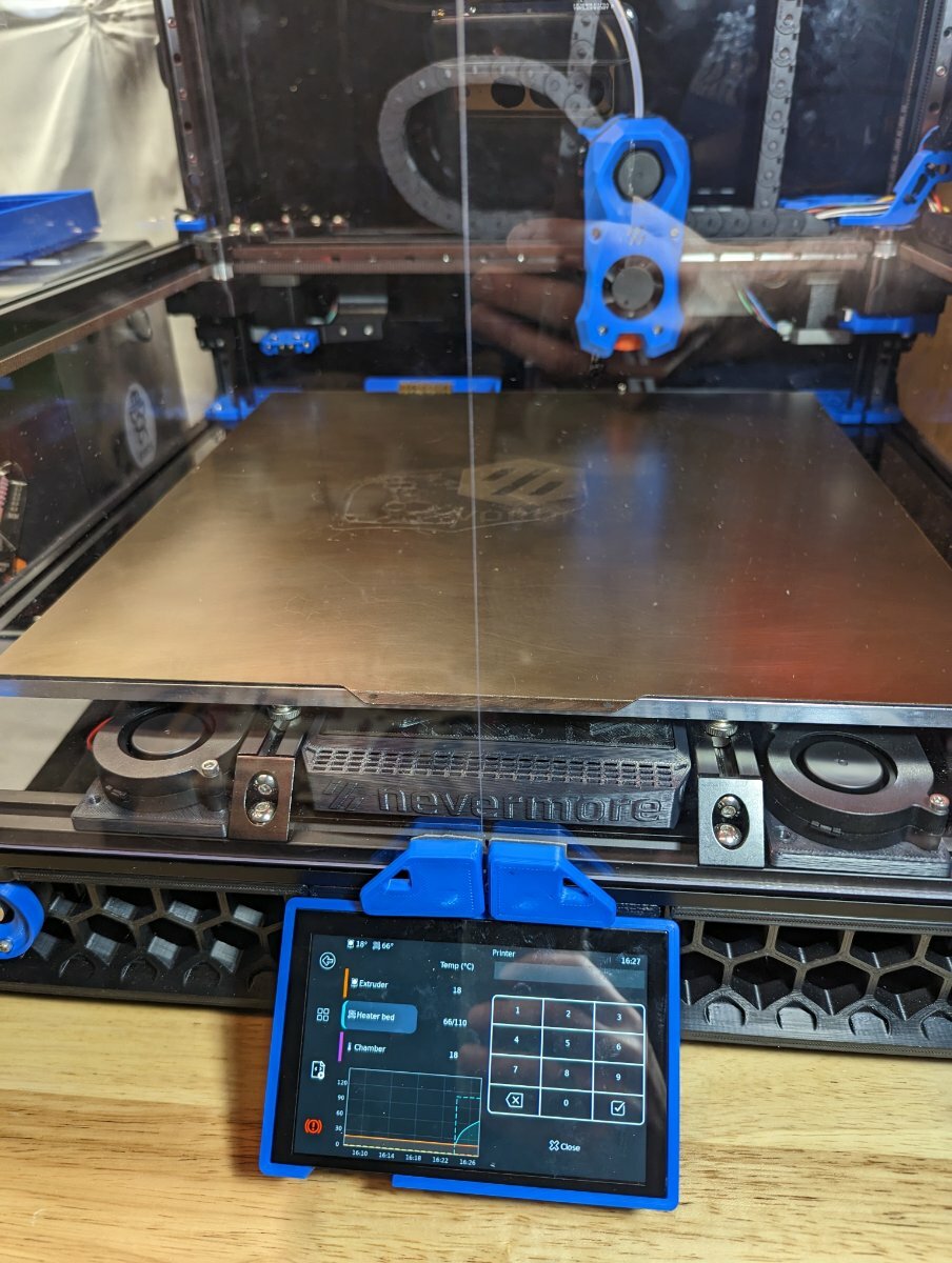
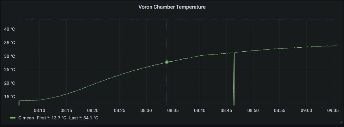
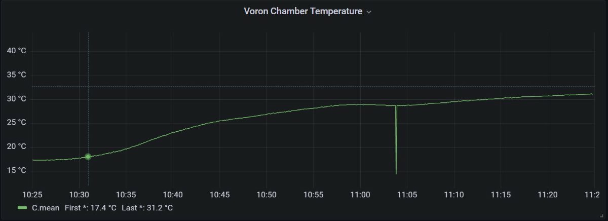
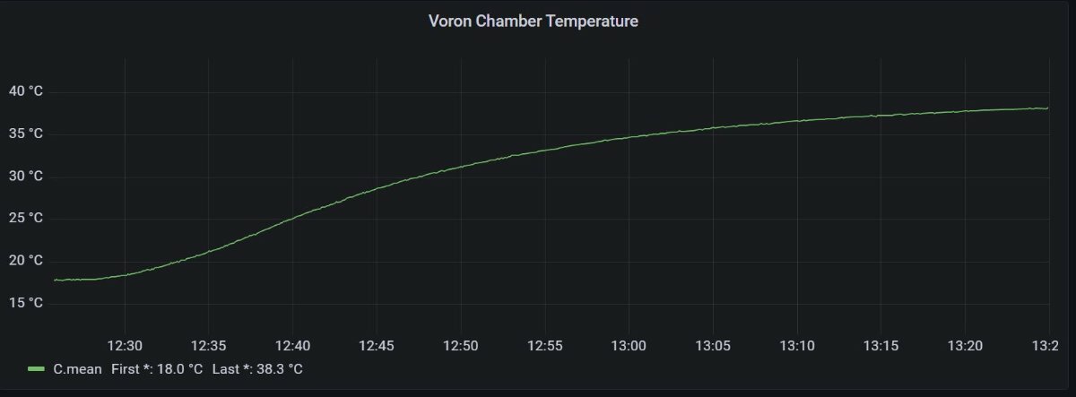
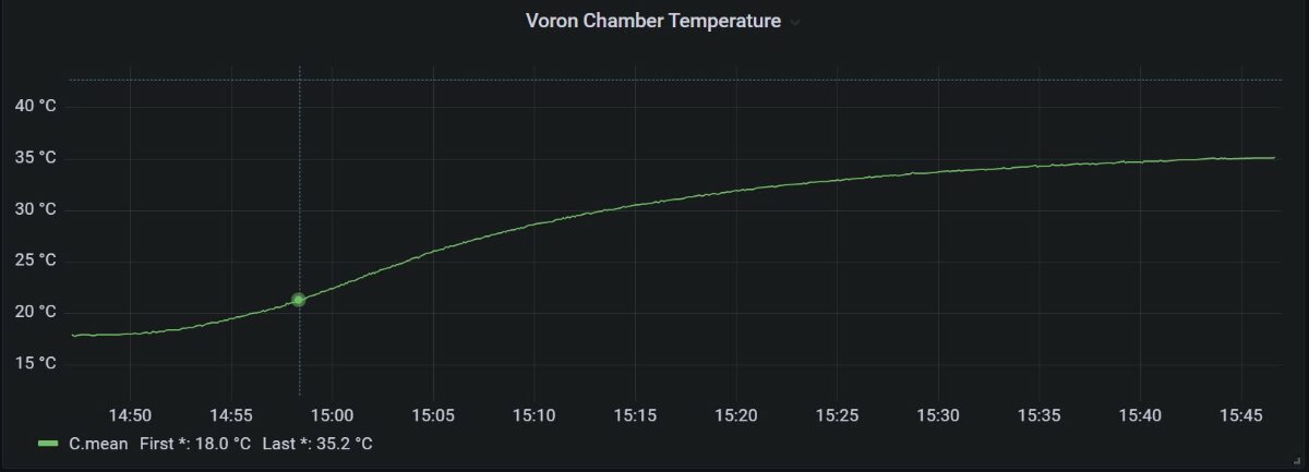
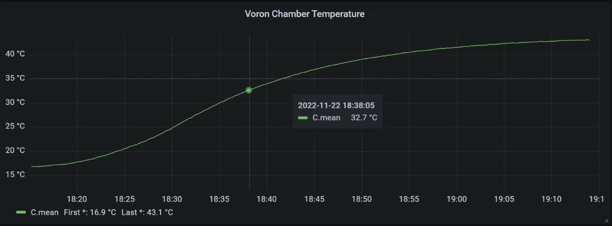
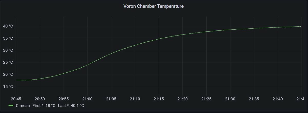


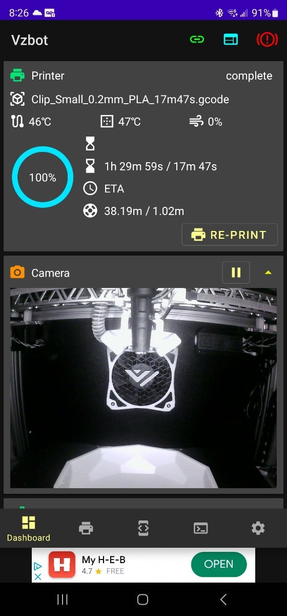
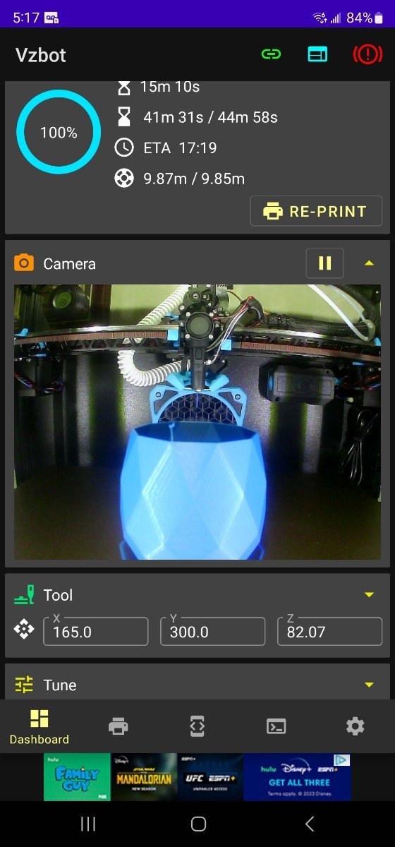
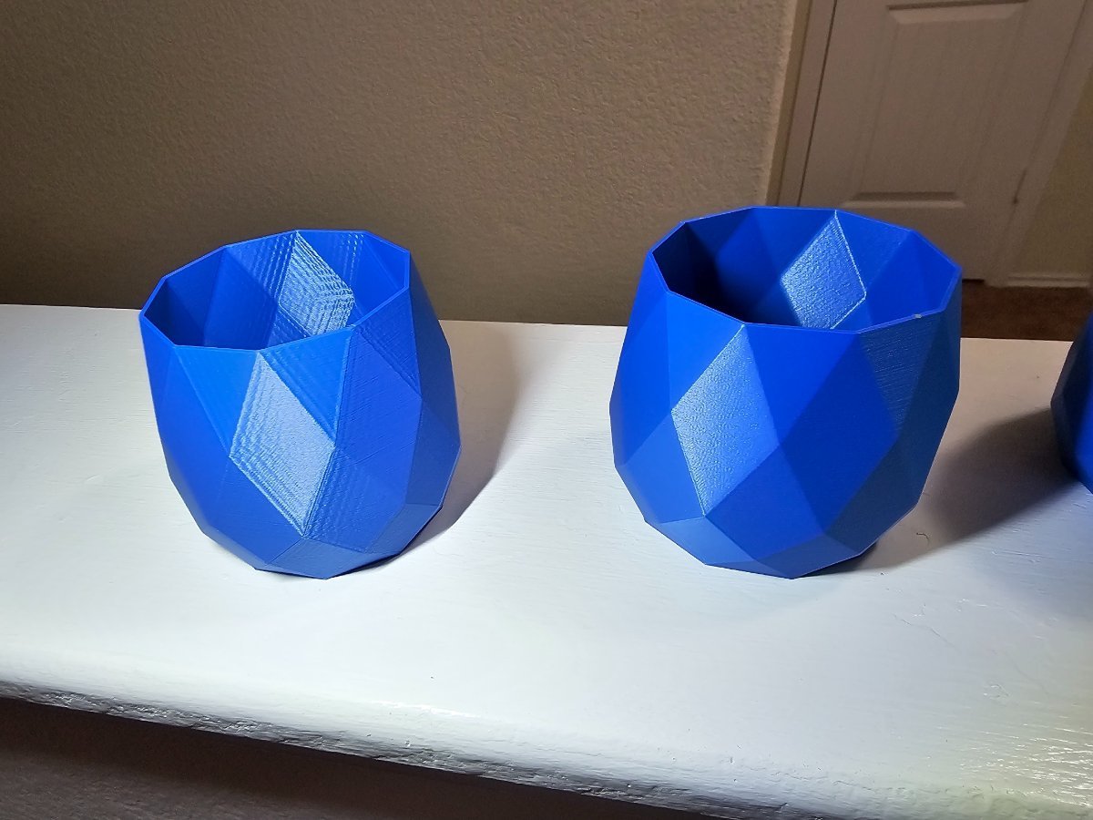
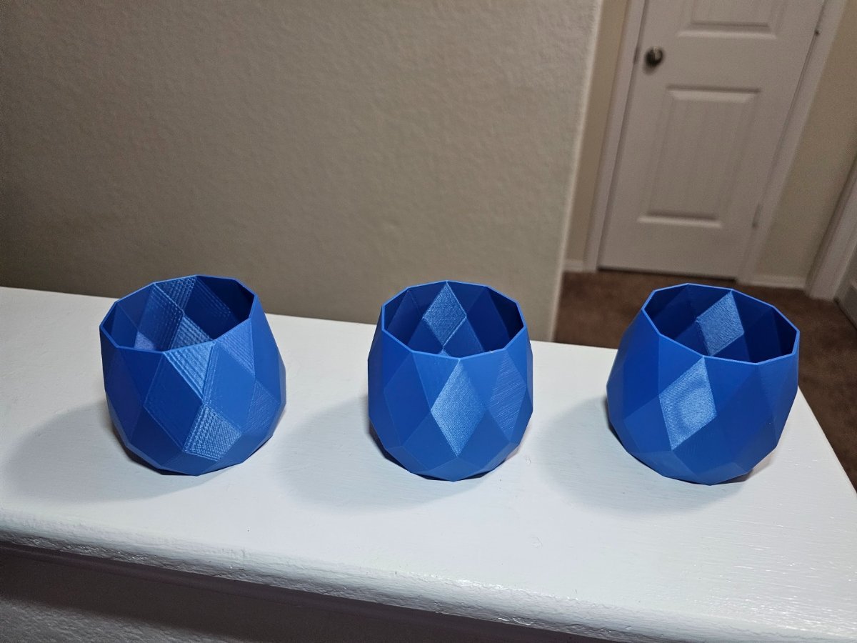
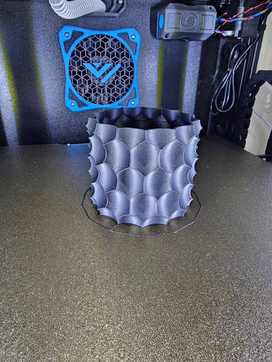
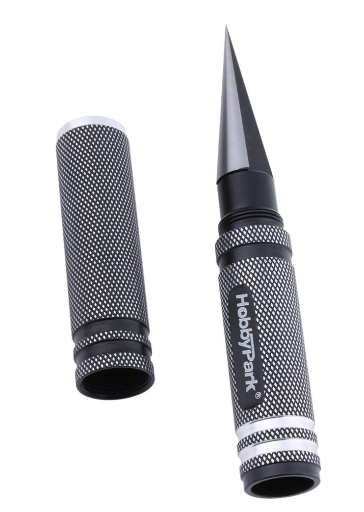

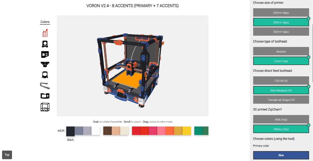
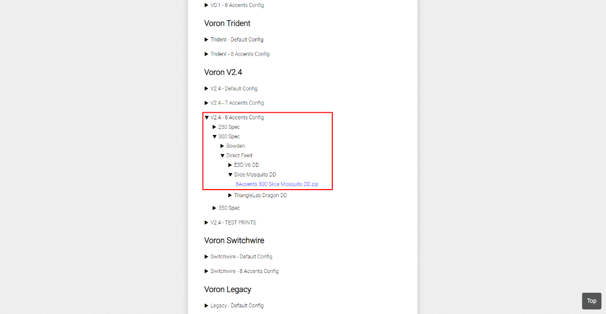
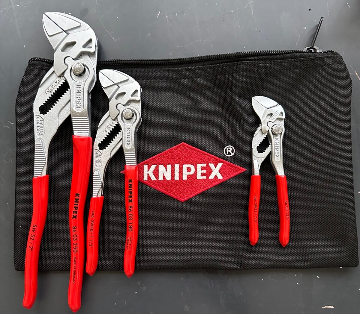
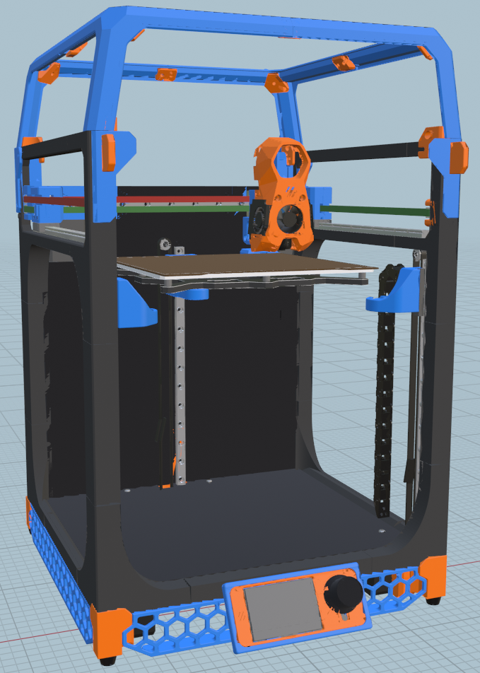
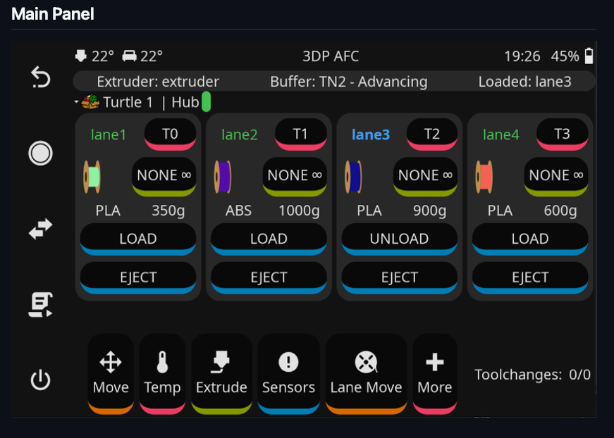
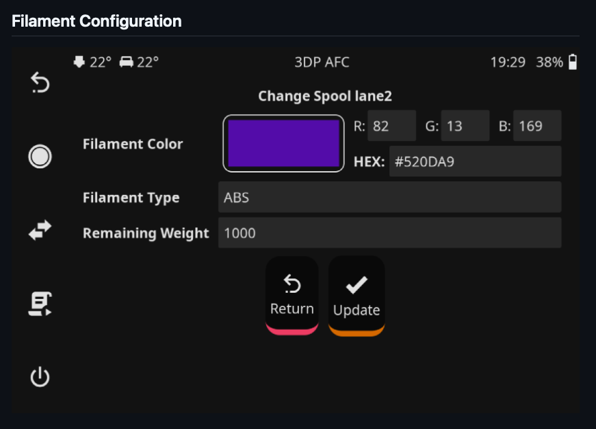
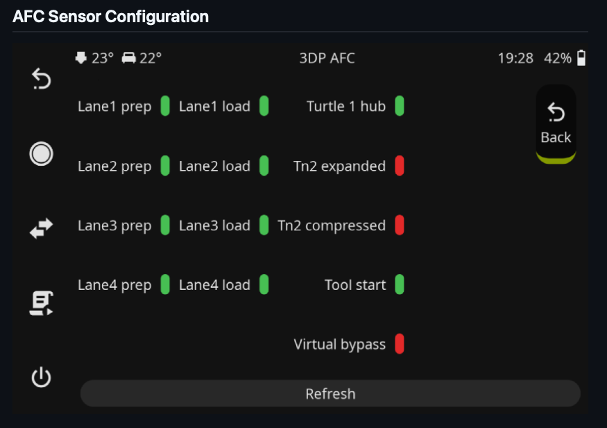
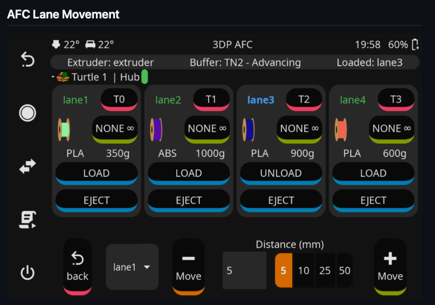

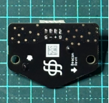
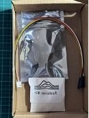
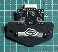
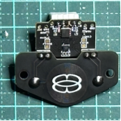
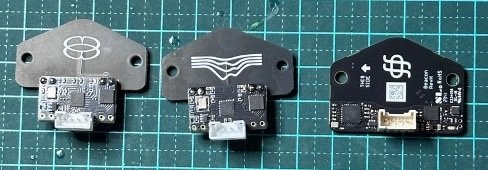
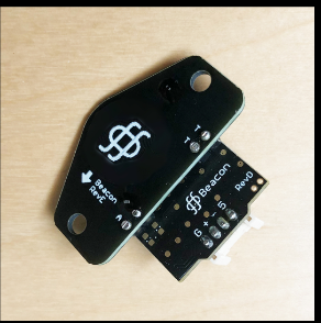
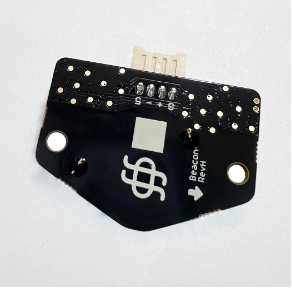
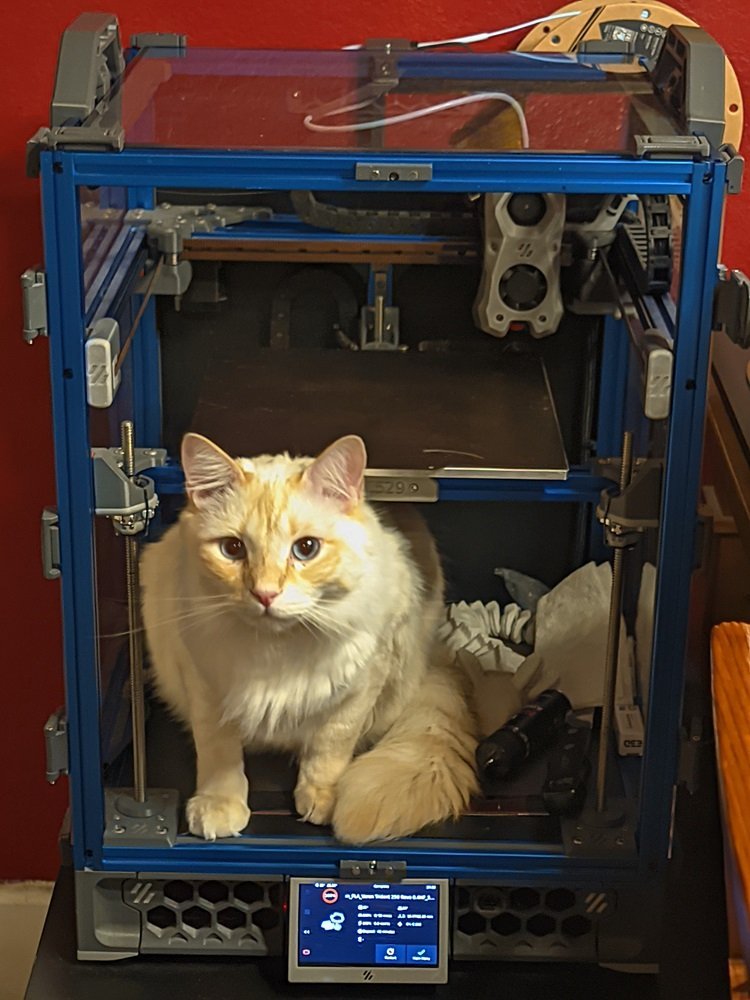

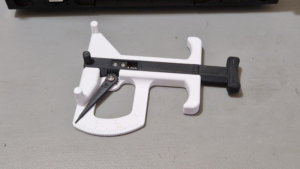

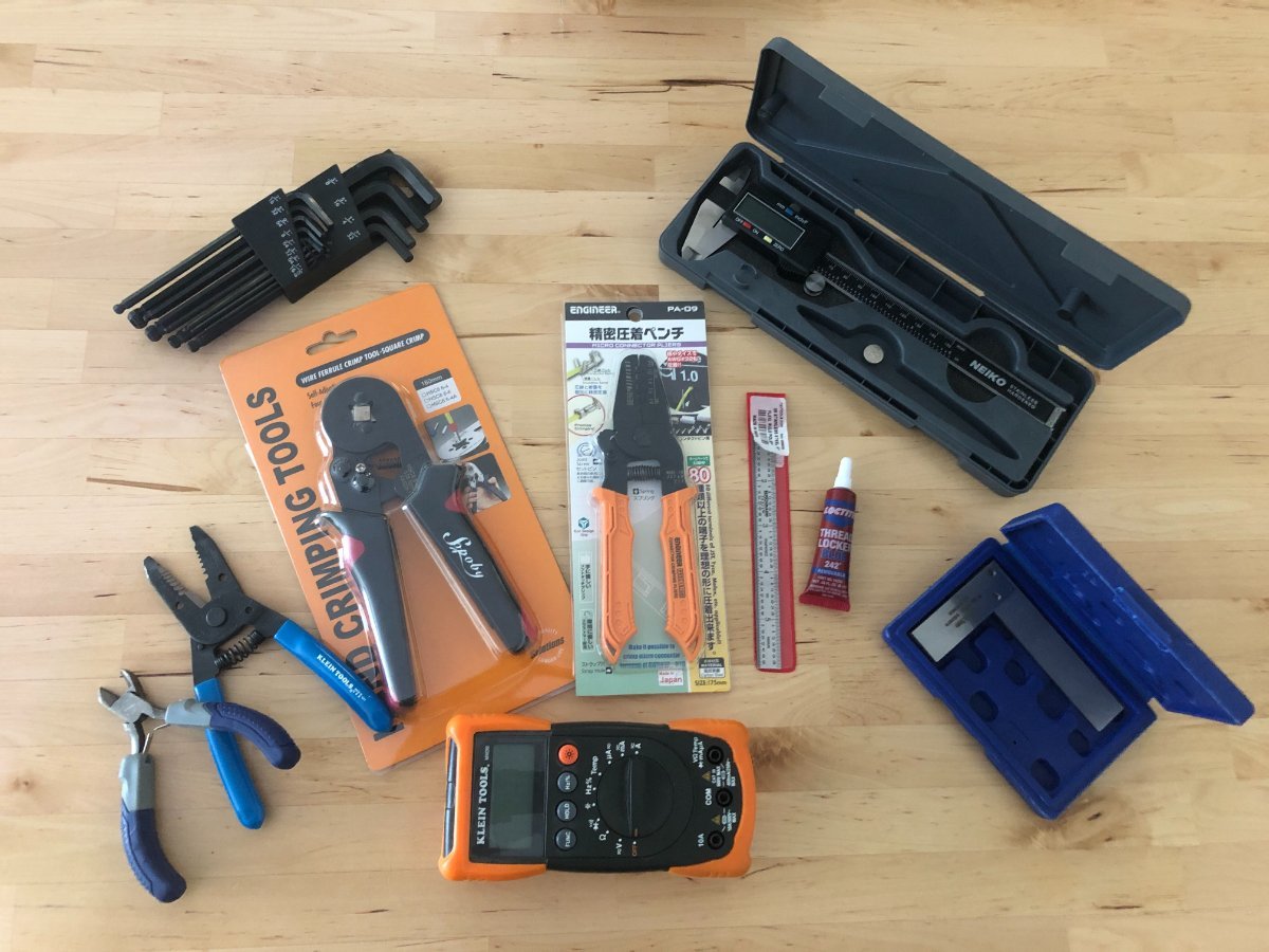
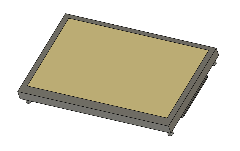
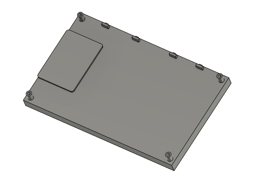
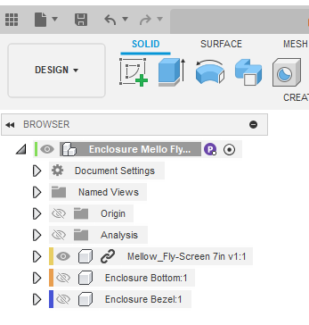
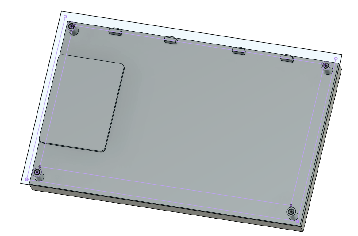
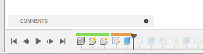
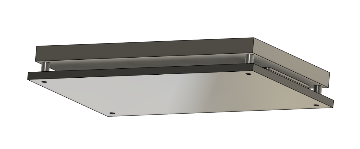
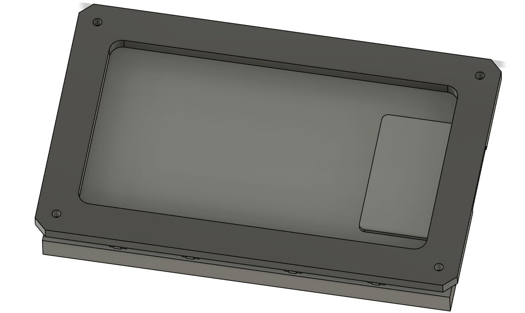
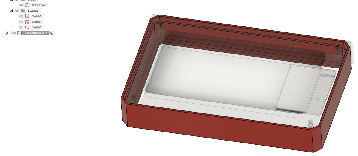

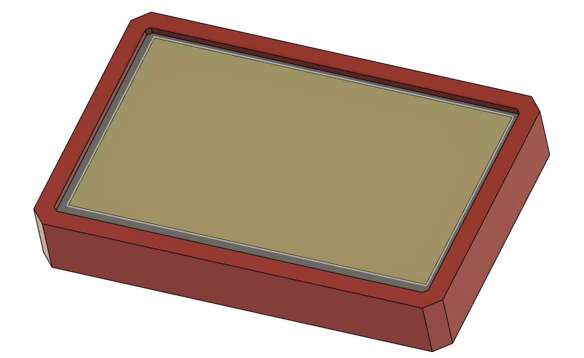
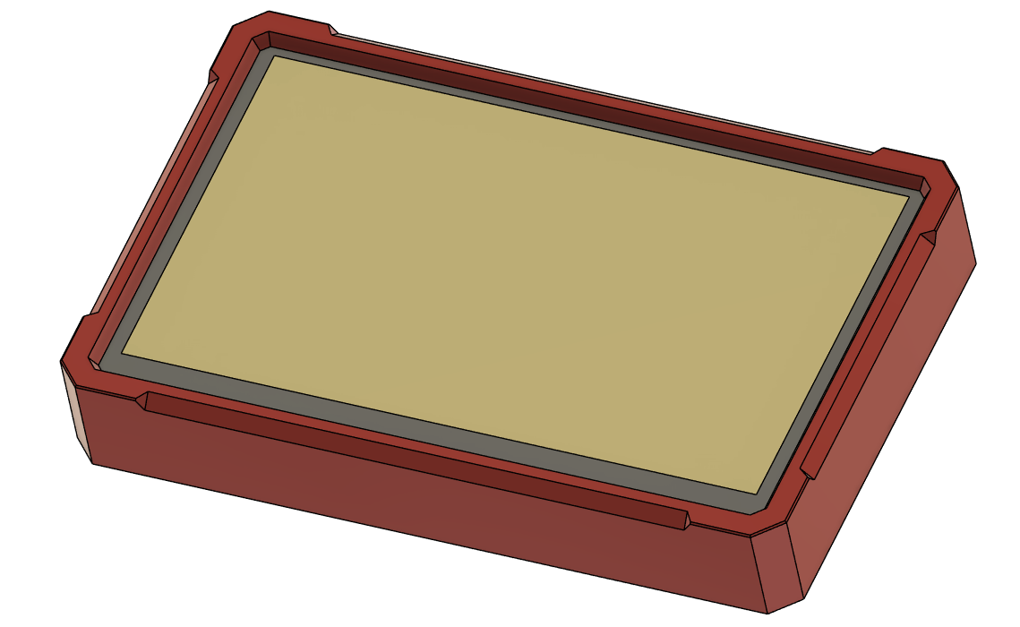
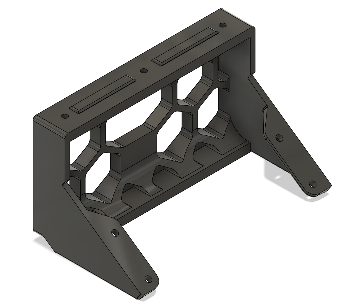
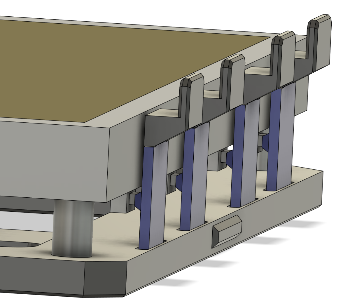
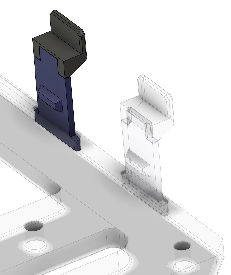
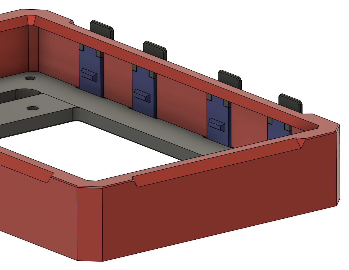
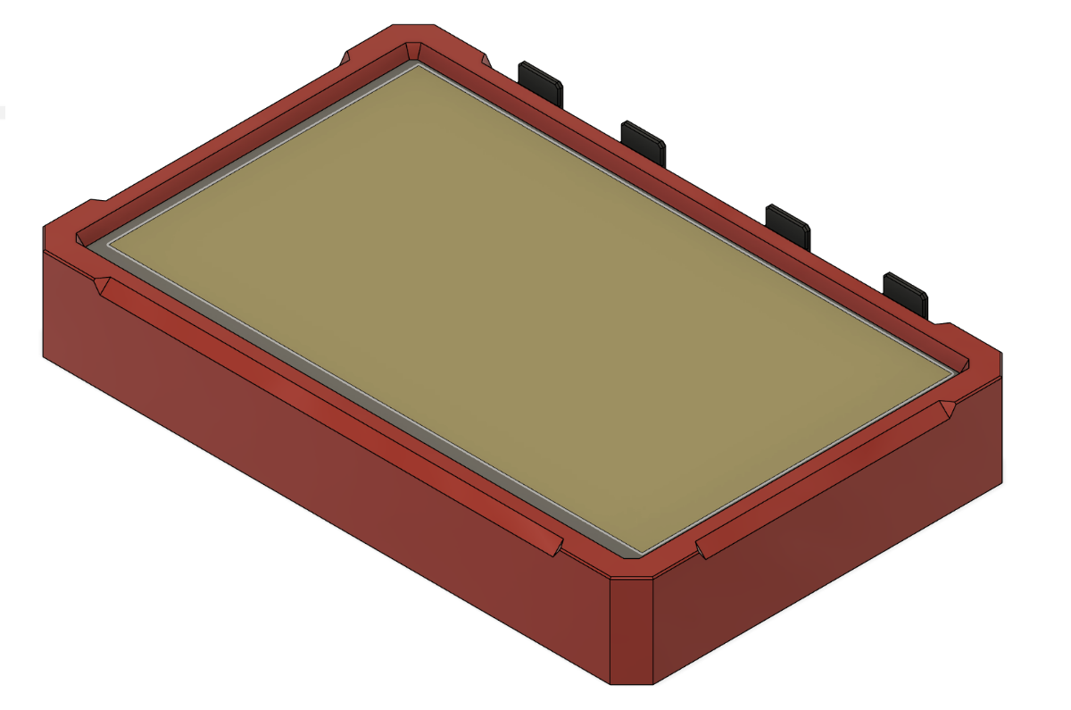
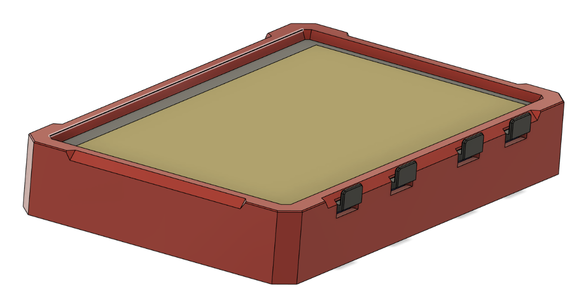
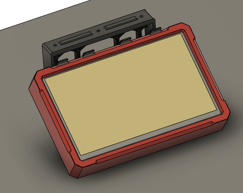
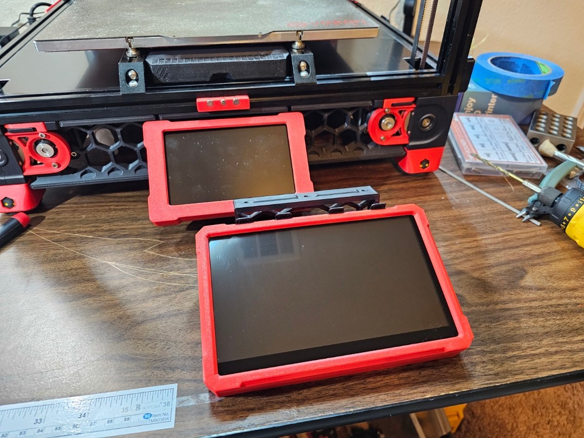
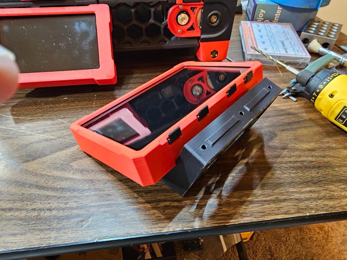
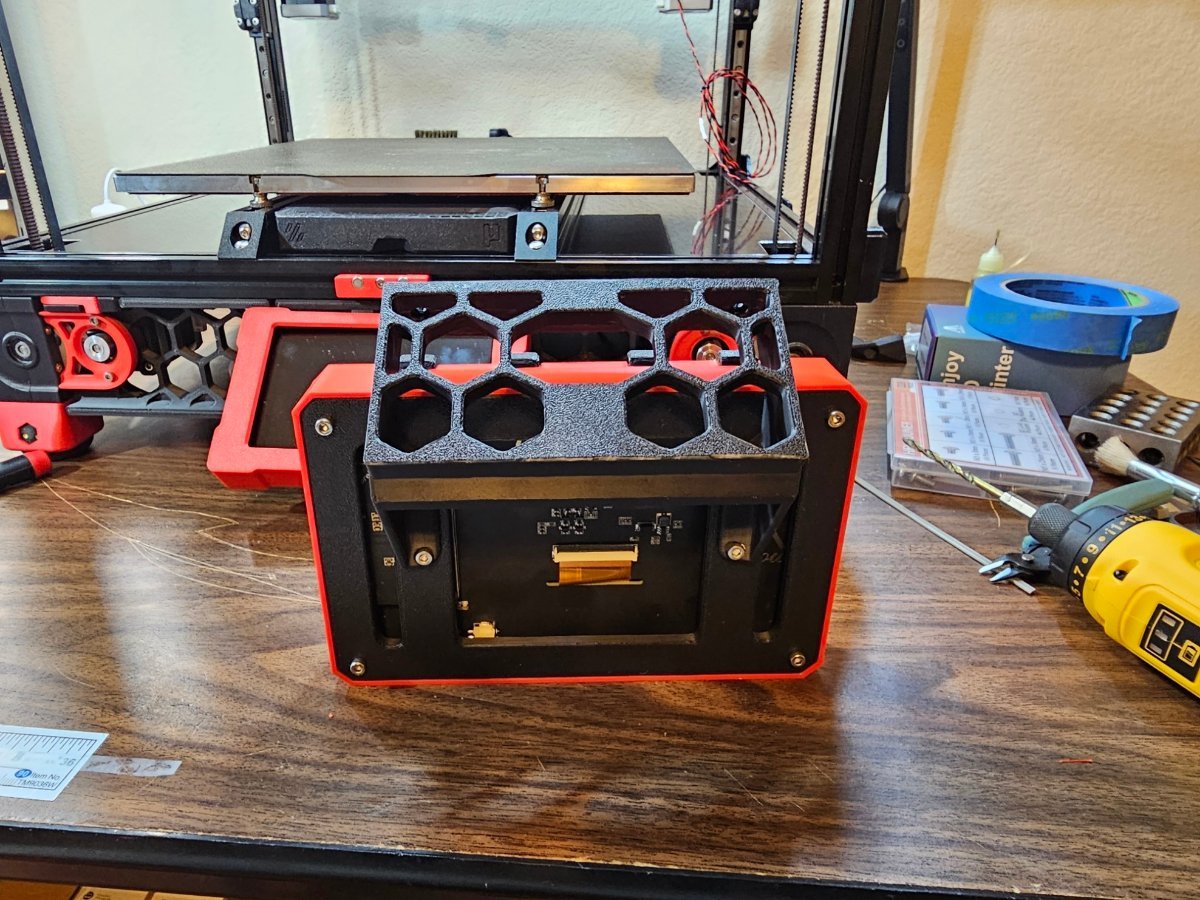
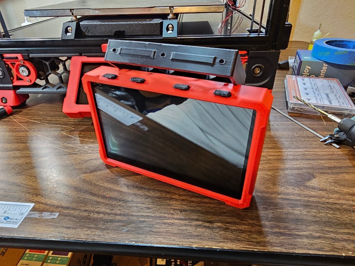

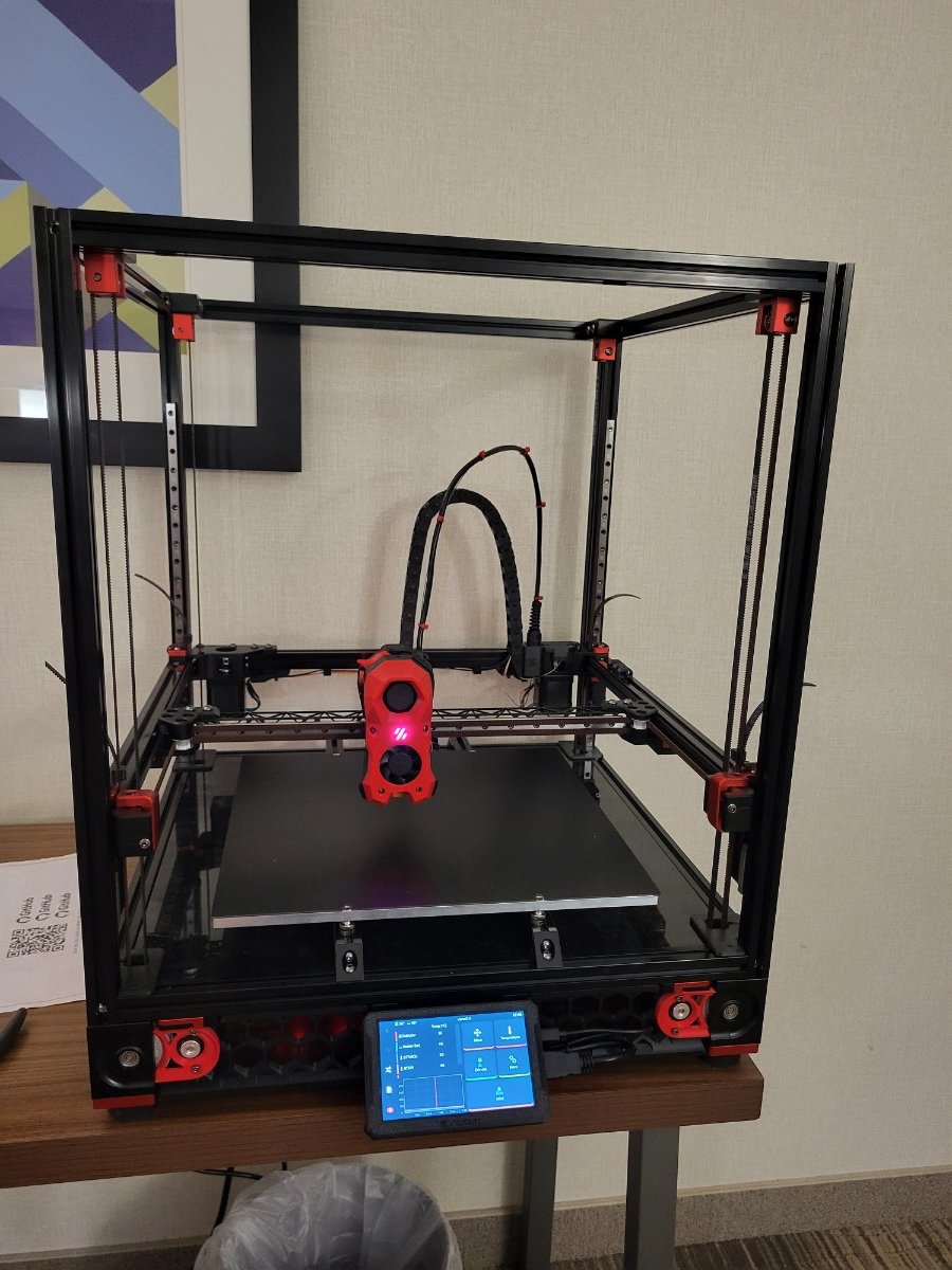
.png.df1c1854485ad177931741d40bf674a9.png)
.png.450c4fe76dab2213ccbd2dd10358b845.png)
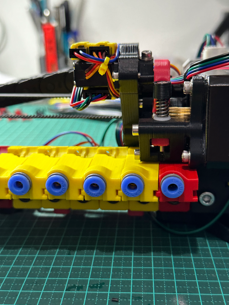
.png.984263d0d2d4af988958eb82ab0f414e.png)