Leaderboard


Popular Content
Showing content with the highest reputation since 05/16/2025 in Posts
-
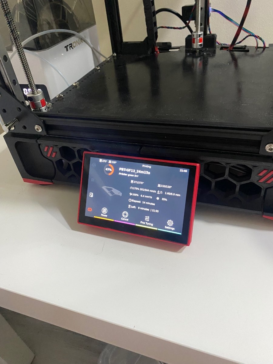
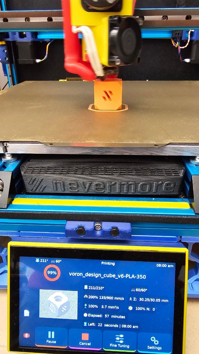
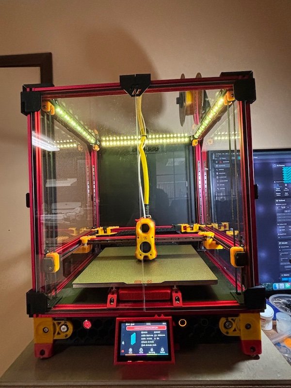
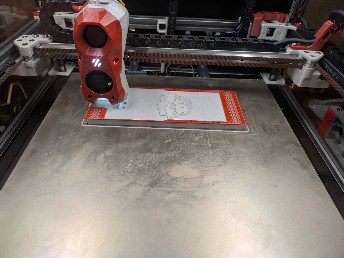
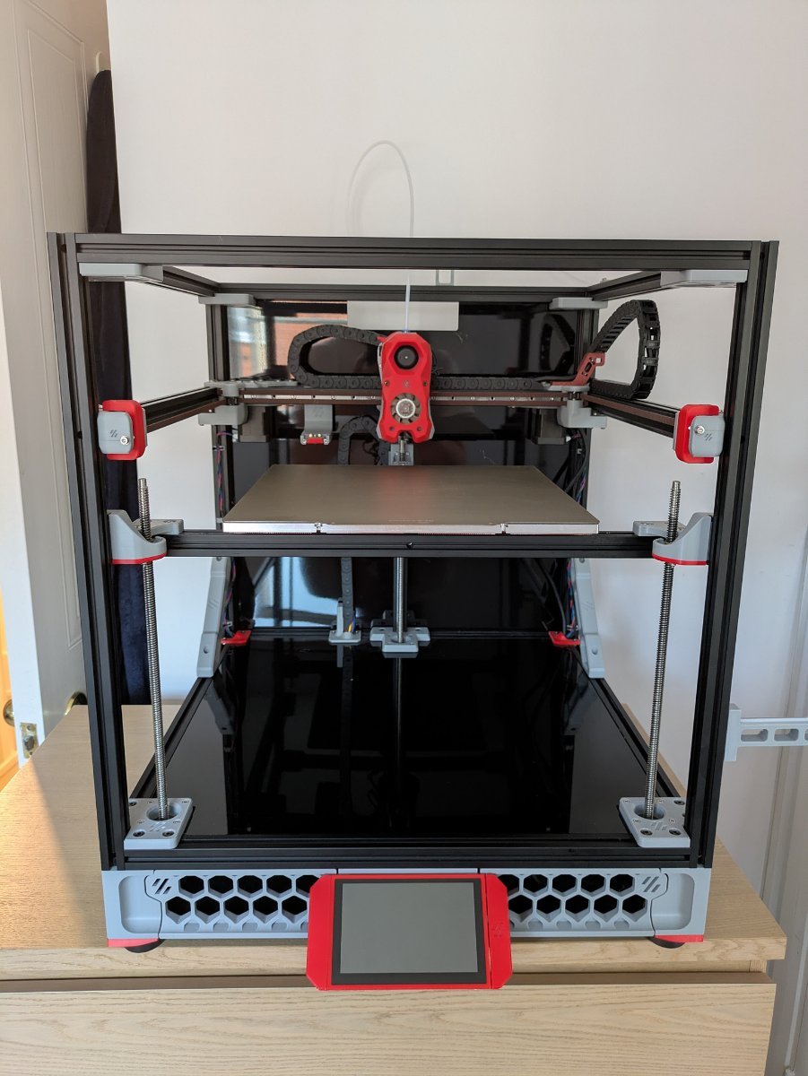
I’ve installed all stuff I posted before and btt hdmi5 screen and sfs 2.0 and… it’s printing!)
 4 points
 -
Remember: these are glorified, computer-controlled hot glue guns. Off by a hundredth of a millimeter is fine. The gooey plastic will compensate.3 points
-
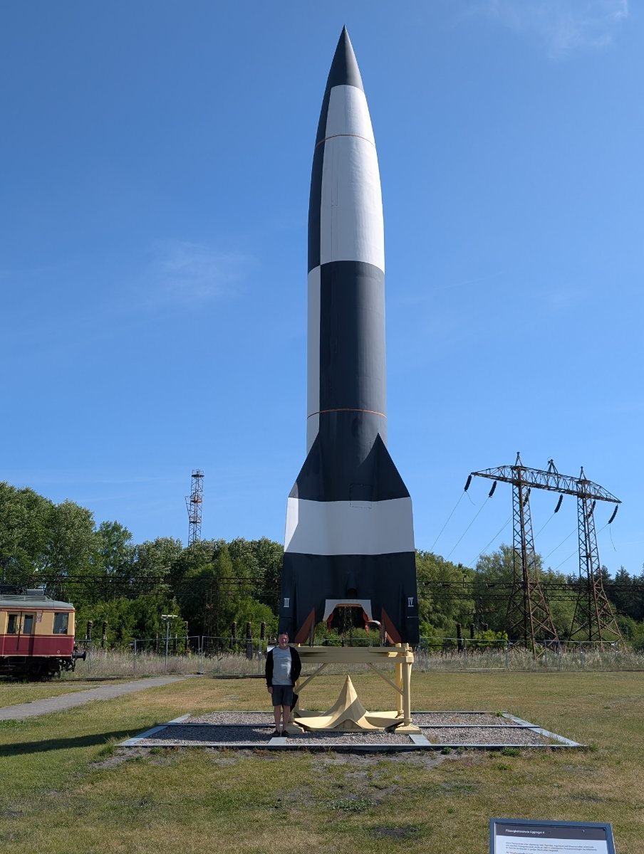
The other week I managed to get to the Technical Museum in Peenemunde to take a look at the V1 and V2s. Here's a link to a google photos folder with some more interesting items - https://photos.app.goo.gl/W1YHz6L7rruZuHEE7
3 points
-
First chips on the Milo!!! First Chips.mp43 points
-
Stealthburner Was a quite easy to build with the manual. Had some trouble with the correct wireing but nothing major. Fans fitted perfectly. The LED housing in the middle so to speak was a bit tricky. Take care while attaching the Front plate to the back. It needs to allign perfectly otherwise you could damage your EBB board...3 points
-
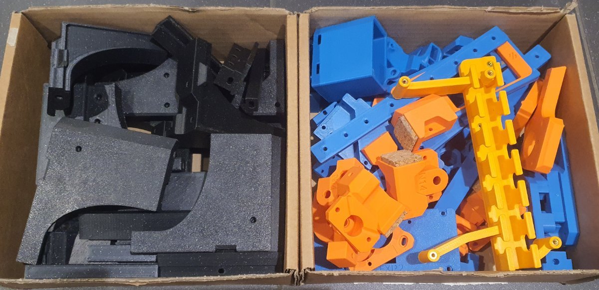
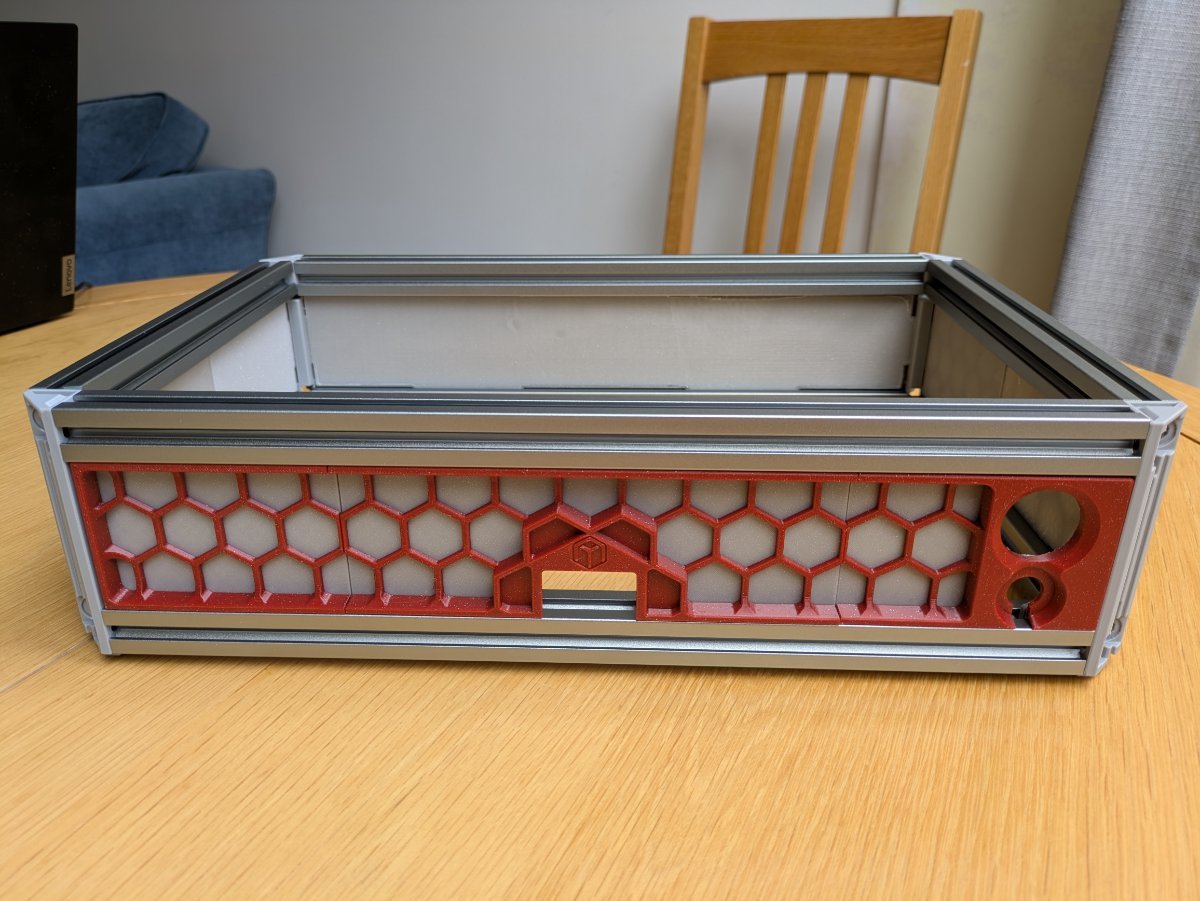
After 58 hours of printing I have all of the parts ready! The hidden snap pins are very handy for holding the parts together during assembly. I'm not sure if the tophat would look better in color or in glitter black like the rest of the frame. I also have most of the components on hand. I have a lot of heat-set inserts to install while I'm waiting for the last orders to arrive...
3 points
-
Nope, I get good results with the standard TEST_RESONANCES AXIS=X & Y from the command line. I have beacon probes on 4 of my 5 printers that all have an onboard ADXL345. My Voron 2.4 being the slowest. FWIW... the loud stepper phenomenon is just a function of print speed and doesn't affect quality. It's just something that I noticed on my 1st print on a new Orca profile. 30 minutes later I had it all worked out. Not a big enough deal to make a deep dive into an already solved problem. Thanks for the recommendation though.3 points
-
3 points
-
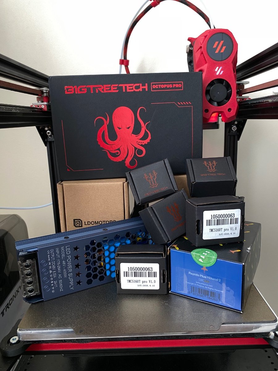
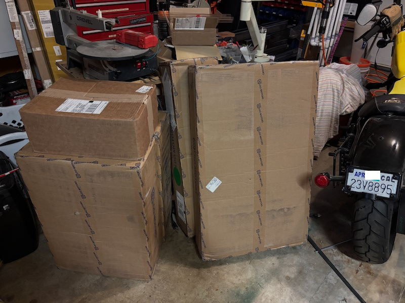
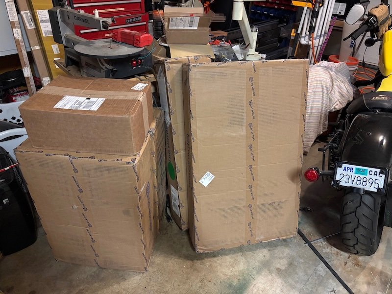
Other stuff has arrived. Thinking on put it all together on a weekend
3 points
-
The jumper pins for the UK 2.5 terminal strips arrived today. I installed them and powered the Milo, hooray!!!!
3 points
-
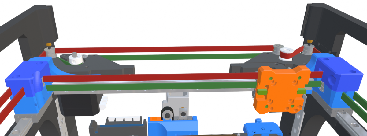
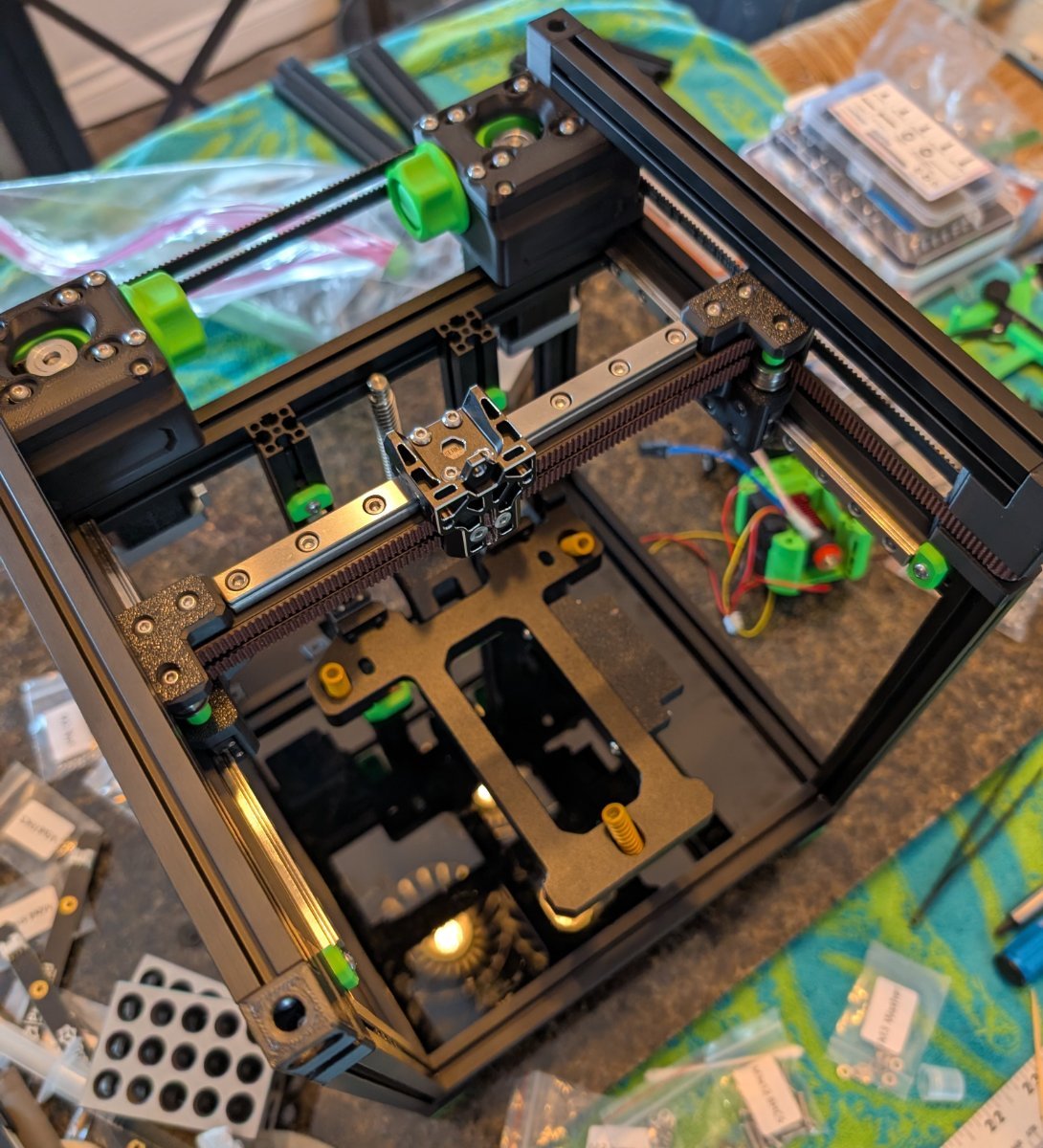
Yeah I like the metal bed option better even though it's a bit heavier. It's probably comparable to the original bed with extrusions. Fortunately, West3D is only a 20 minute drive from here and they had it in stock. I'm also using an MGN9C X rail. Belted up!
3 points
-
Went with the Fysetc metal bed. Smooth as silk now.
3 points
-
That's the one that caught me on my VZ330 AWD build.2 points
-
Monitor the fan noise ,if its gettng louder then replace ,your asking how long is a piece of string ? good fans will last ,cheap fans will not .2 points
-
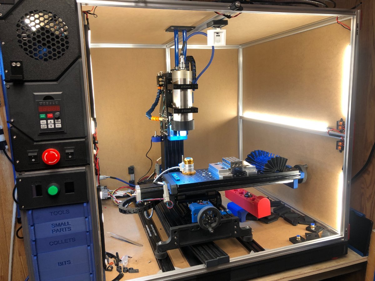
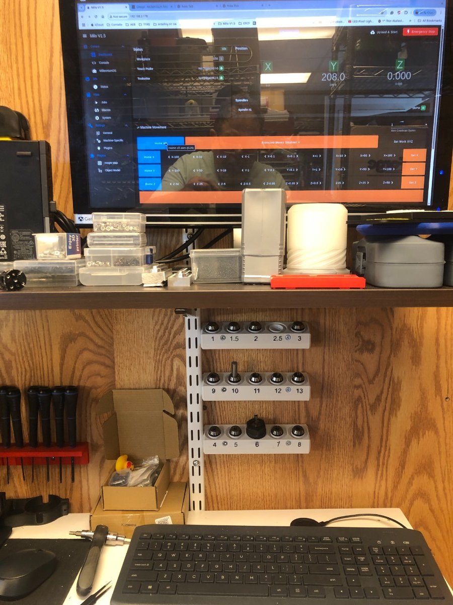
Wired in the coolant relays today, I need to complete the air plumbing and wire the solenoids. Wired the pendant e-stop in series with the Casa e-stop, I couldn't get the software e-stop to work with the pendant. I printed some wall-mount ER20 collets. It's nice that the Casa has a collet drawer, but in reality, when doing tool changes and opening and closing that drawer isn't very convenient. In my opinion, having a pendant is a must-have mod; moving the axis to line up the touch probe is significantly easier than using the RRF GUI.
2 points
-
My VZBot 330 runs on an Octopus Pro board with 48V 5160 drivers. As a matter of fact all my printers are running Octopus boards. Have not had a problem on any. With the 5160 drivers it is important to note the wiring to the drivers as this is cause for the most issues I had. You will also need to connect the two power supplies via GND in order for the 5160 to operate. I am currently in the process of converting a Ender Plus to an AWD Mercury One with a 5 toolhead Lineux Toolchanger and this will run on an Octopus board with 48V 5160 drivers.2 points
-
I put a GDSTIME fan in my Stealthburner about 3 years & 3500 hours ago. Still running strong.2 points
-
Hi Kris. Just wanted to say thanks. Great service and customer accommodation. Definitely fast shipping. V2.4 kit LDO Milo 1.5 CNC + Casa
2 points
-
It's so good, im one for my Vz330.2 points
-
Thanks! Yes, I'm pretty pleased with the first cuts. Still need to learn more about the Cam setup. Learning by trial and error. Looking at ordering more end mills and still setting up "Air Blast" and MQL coolant.2 points
-
Oh yes! I forgot to mention that one it would be my first upgrade mod on a new printer.2 points
-
My V0 is almost complete. Next.. Milo 1.5 +Casa
2 points
-
Fridge door conversion was my best mod. Finally, a door that seals and keeps the fumes inside so the filter can take care of it. I print mostly ASA, so that is important. Second is converting my TAP to Dyze Horizon strain gage nozzle sensor. Way better than tap and 100% reliable and repeatable. I am currently working on an Orbiter3 conversion to enable reliable printing of TPU.2 points
-
Trying something a little different with the trays:
2 points
-
Well the Box Turtle build has started. Colours for my 2.4 but it will start life on the test mule (Trident). Probably not worth a separate build log as there are a couple of good ones on here already. Build is 1/2 LDO and 1/2 Ali with a mix of ABS/ABS+ M600 filament change is great but is also a curse as it requires some babysitting - hopefully this solves the issue
2 points
-
Replacing TAP with E3D RevoPZ made the largest print quality difference so far. Replacing the BTT SB2209 with a Mellow SB2040 stopped an appetite for Hotend Thermistors.2 points
-
I second the Beacon probe, for sure, as a reliable first layer. I run sensorless homing on both my printers it works flawlessly when properly set up.2 points
-
Switching over to Beacon was a game changer for me. I also changed the extruder / hotend over to a Orbiter 2 and Rapido 2 UHF.2 points
-
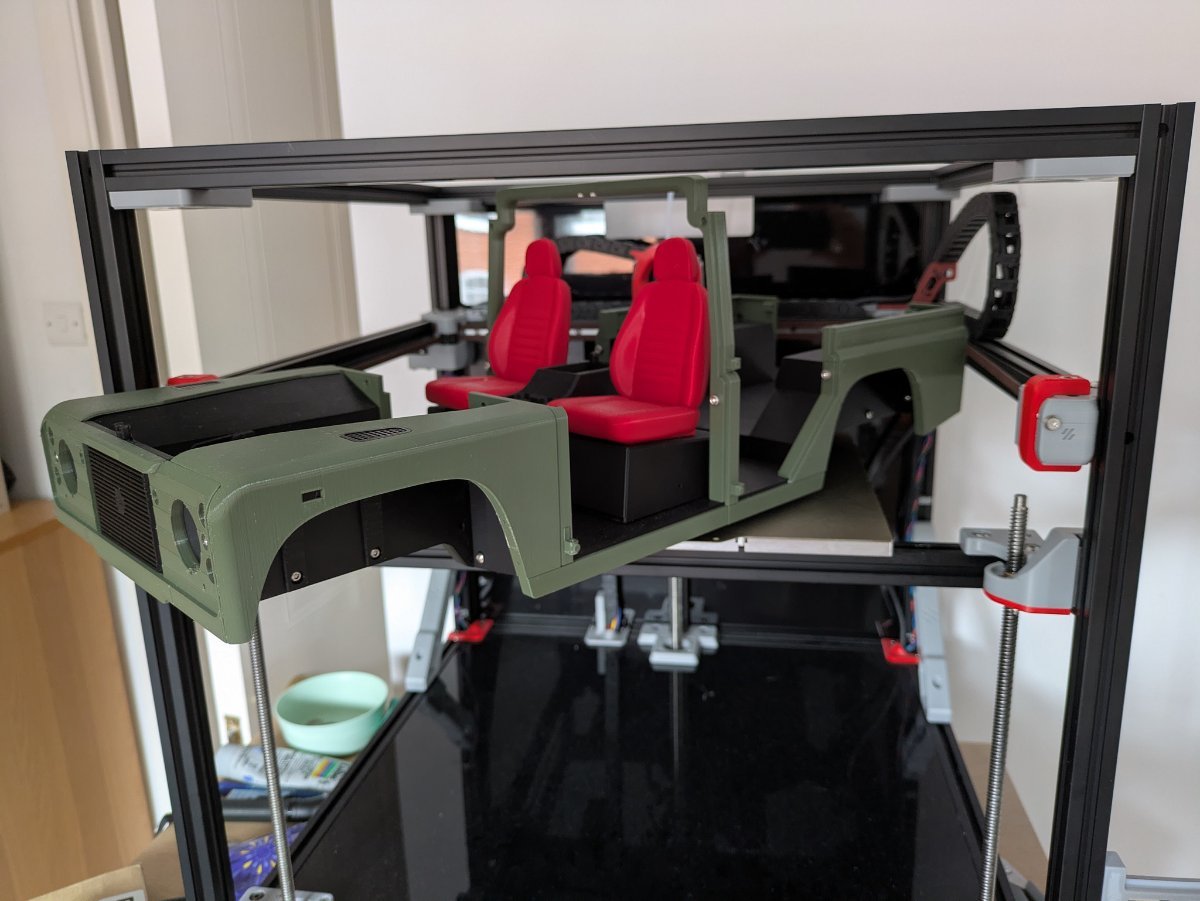
Update: 200 hours in and the Stealthburner certainly isn't a PLA queen but have managed to get through most of the PLA prints with reasonable results. All of the 3dsets Land Rover Wagon were printed and, i would say, 95% were very good. The other 5% are challenging and I am wondering if it is an issue with the toolhead or simply my tuning. I still have not finished it but life has been busy! I will get there .... Build now has a ACM back and lower panel but I have left the acrylic deck on there for now. Brace Brace Brace!! I added a couple of VZBot braces on the sides and used four of the trident Z axis stepper mounts in the top to keep the top square and braced the same as the bottom. I was thinking of popping 4 round LED's in the holes. They worked out very nicely! Running KlickyPCB for endstop and it has not had a fault in the 200 hours of printing so far - so much more reliable with first layers then my 2.4 using the z switch and klickyPCB separately. I have set up adaptive mesh and exclude object (so so easy! why didn't I do this earlier???) - this is native on Klipper now. Still have to clean up under deck but that is tabled for when I get a new toolhead and pass the StealthBurner back to the other machine. So what is next? Toolhead definitely. I am tossing between XOL or A4T-AFC with Galileo wristwatch or spunking up for a LDO Jabberwocky Toolhead & Extruder. This is, after all, going to be the test bed for a Box Turtle and possibly one other MMU/AFC - I want to build one for the 2.4 (simple two or 3 colour for ABS) and one for this .... or if I get one very cheap I could have a go at an ERCF V2. To be continued ......
2 points
-
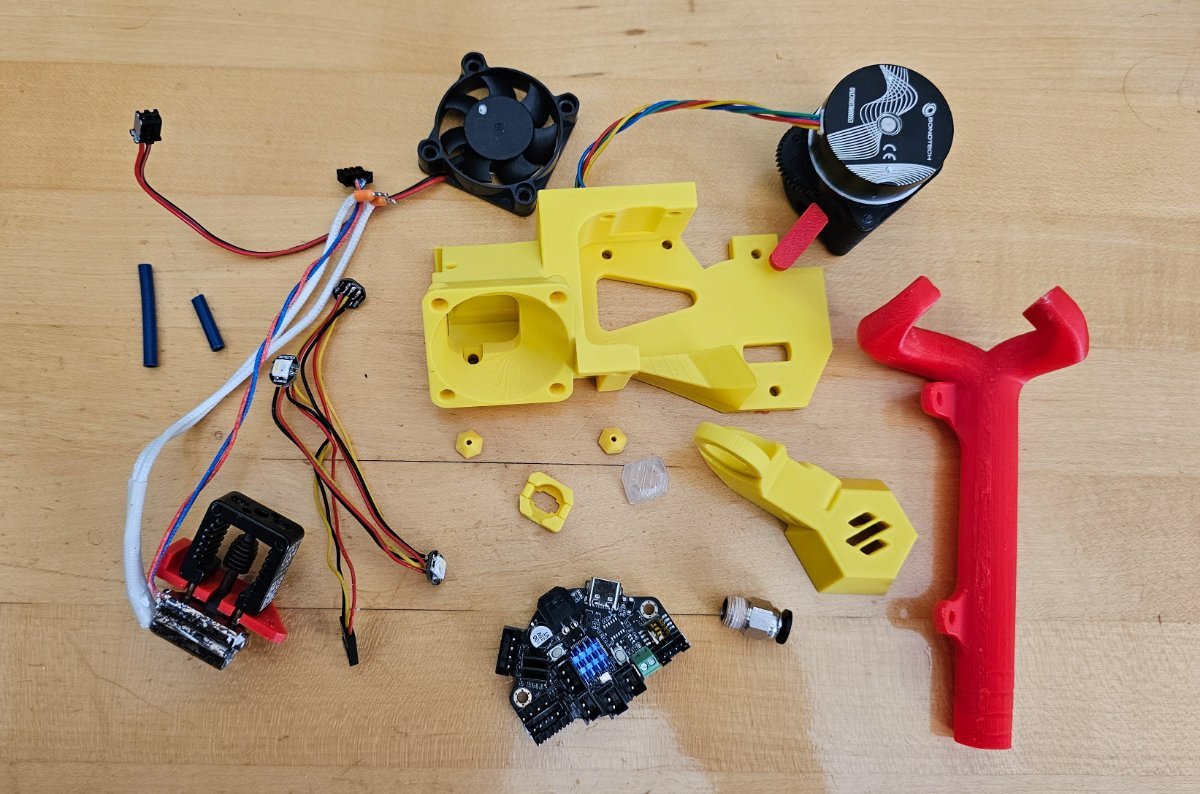
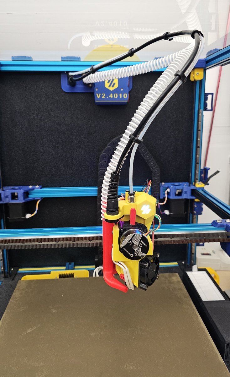
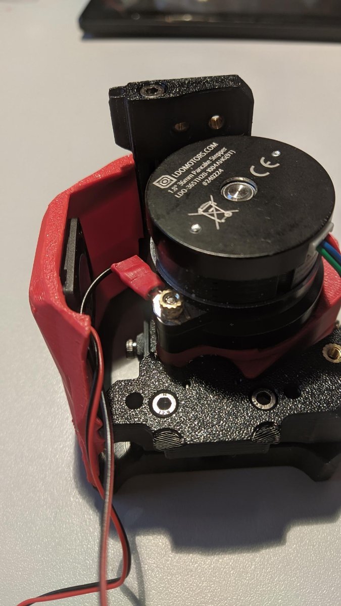
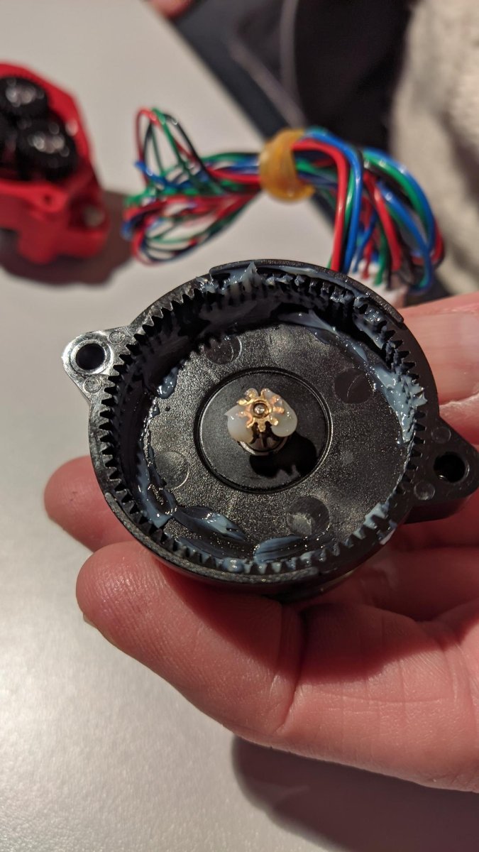
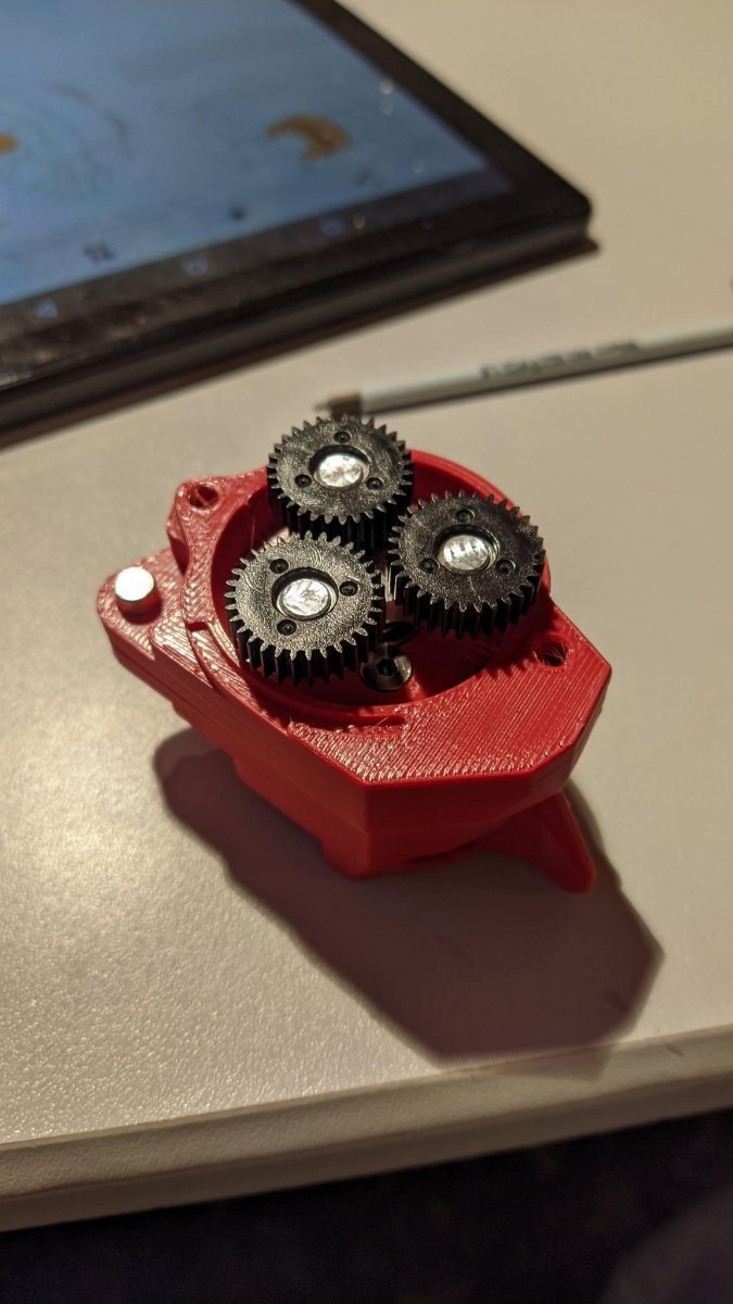
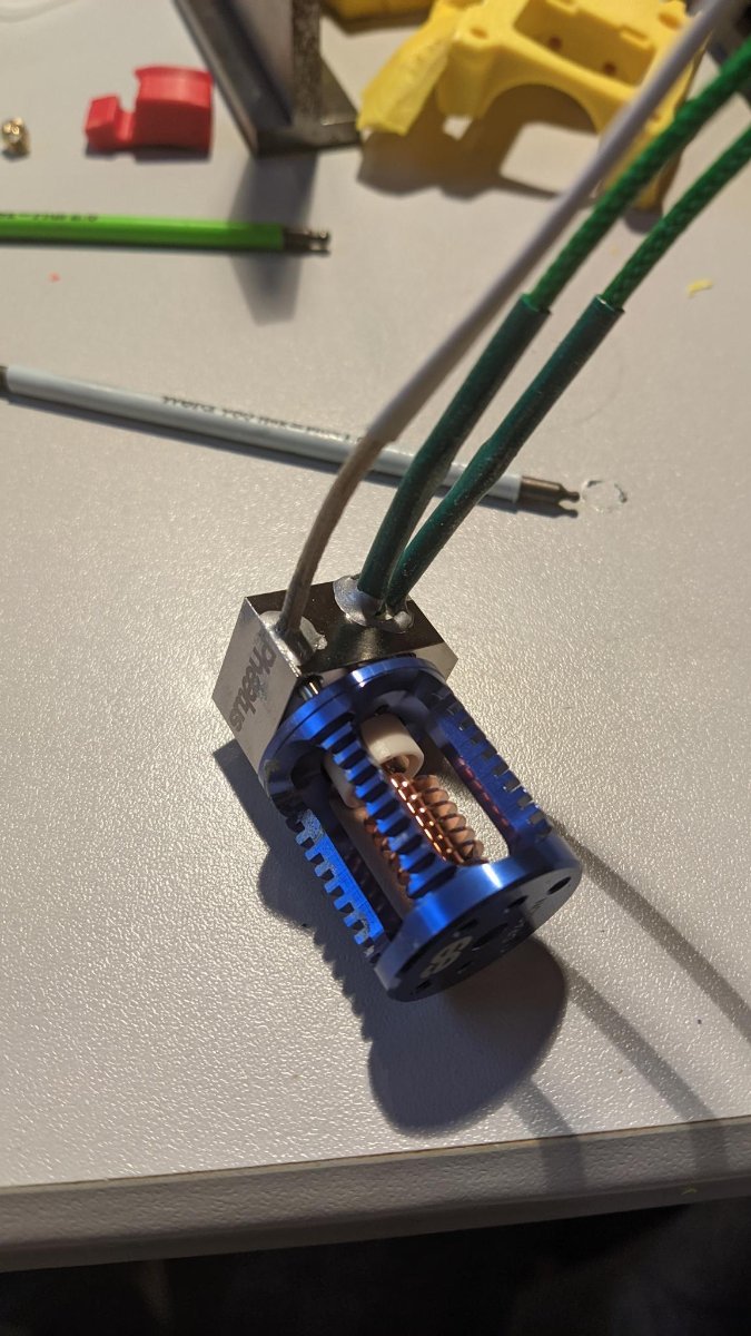
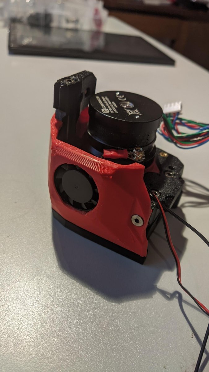
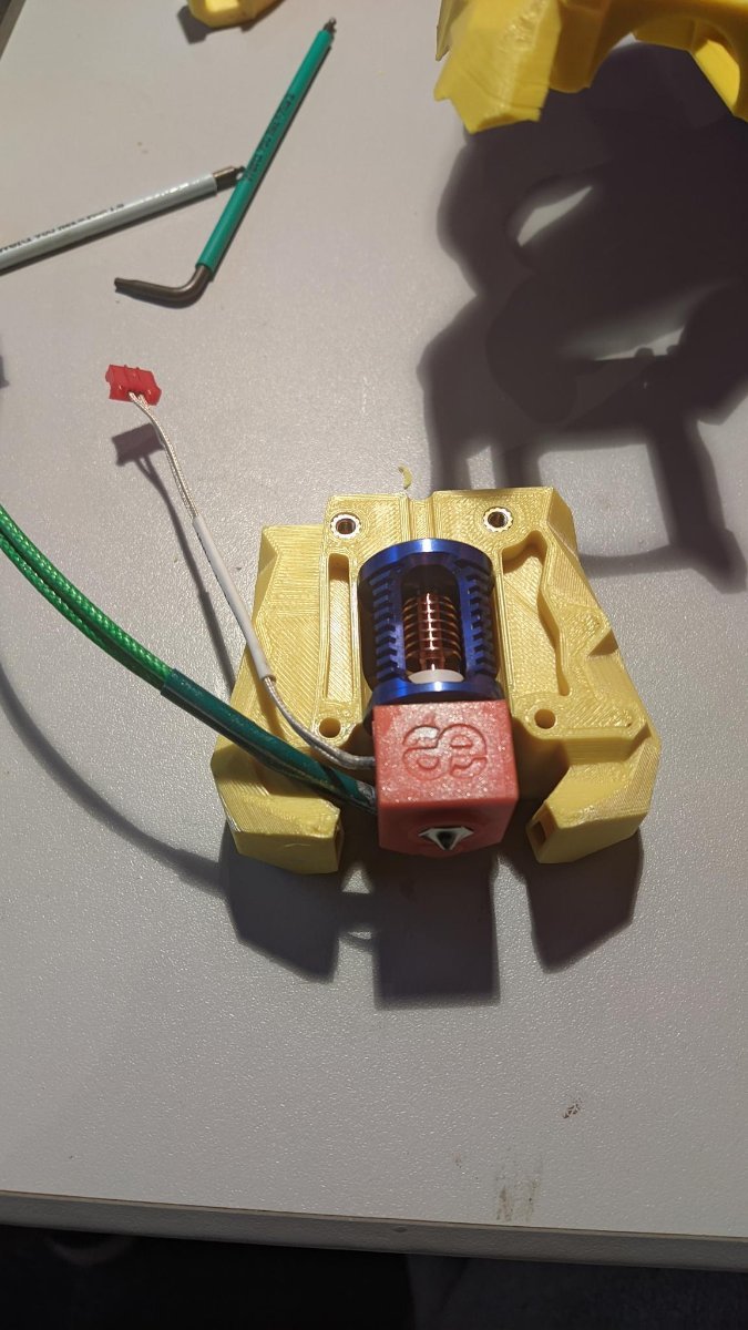
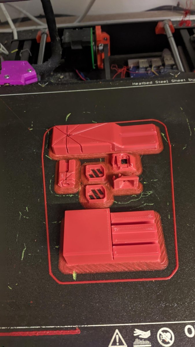
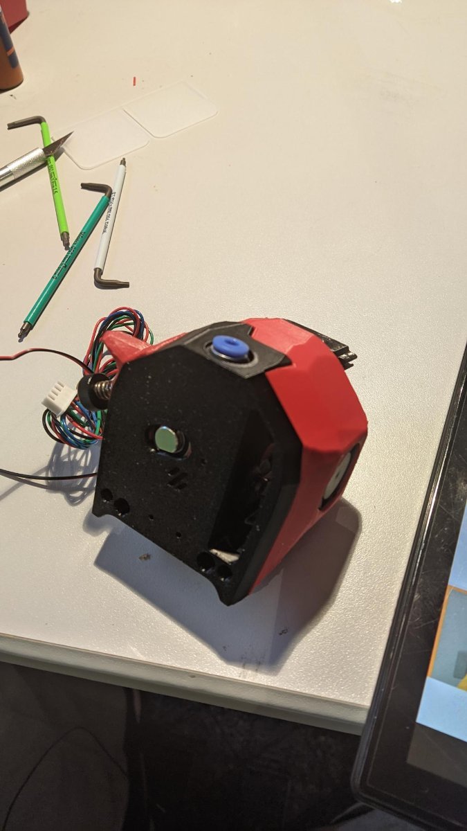
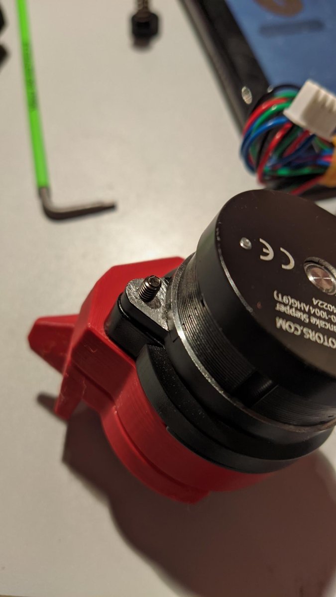
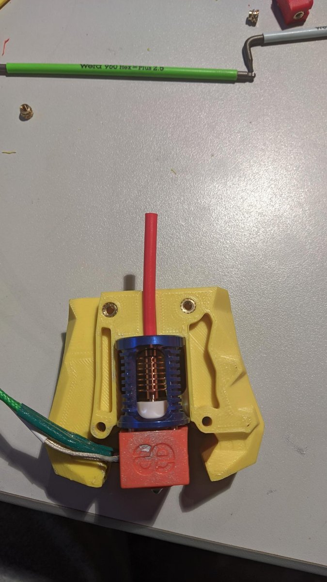
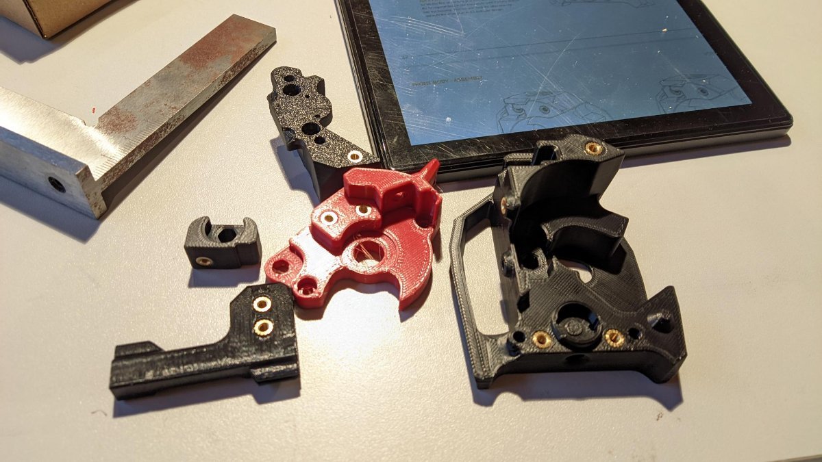
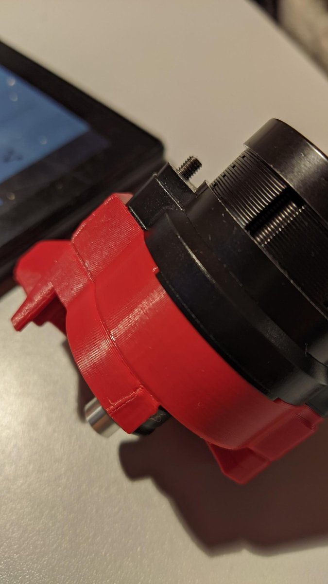
Galileo2 and Hotend Sorry i stopped building for a while for personal reasons but im back on it and im at the wireing right now. So i think i will keep gonging now till it is finished ---- This was the most finicky part of the printer to build. It was ok in the end with the Galielo Manual and the CW2 manual. For clairty it was good to take a look into CW2 how things should fit. Stuff to Note: - I forgot to print some parts for the LED light inside the stealhburner.... - I used thermal paste for the hotend to make it more heat conductable. - I did not print the Galileo2 Parts i had them printed. I did not trust my Prusa with some of the finer parts for it. - Due to static buildup on the filament when it runs trough a PTFE tube it can lead to damage to your steppers, there is an exelect thread on github if you want to know more. However easiest solution is to not use a long PTFE tube for the filament and also ground your E motor for extra safety. Thats what i did on the pics there the wire comes out from the motor. - I also used a latch with a 5v Fan inside. To cool down the EBB board. You can grab 5v from the EBB itselp from the "Probe" connector. -> https://www.printables.com/model/680592-galileo-2-2507-fan-cover-for-sb2209sb2240 The wires are to perfect length tho from Siboor. So that was cool! There is not much to note other than the Parts do not seem to fit together at first and i had to watch some youtube vids to get how to attach the G2 to the Hotend part. I did not use the Stealthburner Hotend part where the hotend actually sits as it would blow on the heatbreak of the hotend and this could lead to clogs. There is a better version on printables. I used this one https://www.printables.com/model/883286-stealthburner-printhead-for-dragon-hf but there is also this one: https://www.printables.com/model/625623-phaetus-dragon-hf-printhead-mount-for-stealthburne Also figureing out how to attach alll this to the CNC mount as it looks so different but the meachnics are nearly the same. For the cable sleeve and the CAN Bus Cable holder i printed this: https://www.printables.com/model/1087611-galileo2-btt-ebb-sb2209-usb-v10-cable-strain-relie Well it took some time and it was quite a while back when i did it so i dont remember all the details but if you struggle, just reply and i try to remember. There are some pics tho
2 points
-
The issue is, there always at few projects half done!2 points
-
Welcome to the forum! Oh noes! A workshop in use, mid-project! None of us here has ever seen or experienced that!2 points
-
I think I've got it now. It appears that my old brain doesn't work correctly when faced with too many variables. The rear of the printer faces into the room, laptop faces into the room but 180 degs away from the printer, the printer motor layout diagram looks front to rear, etc. Anyway, I deleted the stepper motor sections from my printer.cfg and then addressed each motor separately and didn't move on to the next stepper until everything was working and going in the correct directions.2 points
-
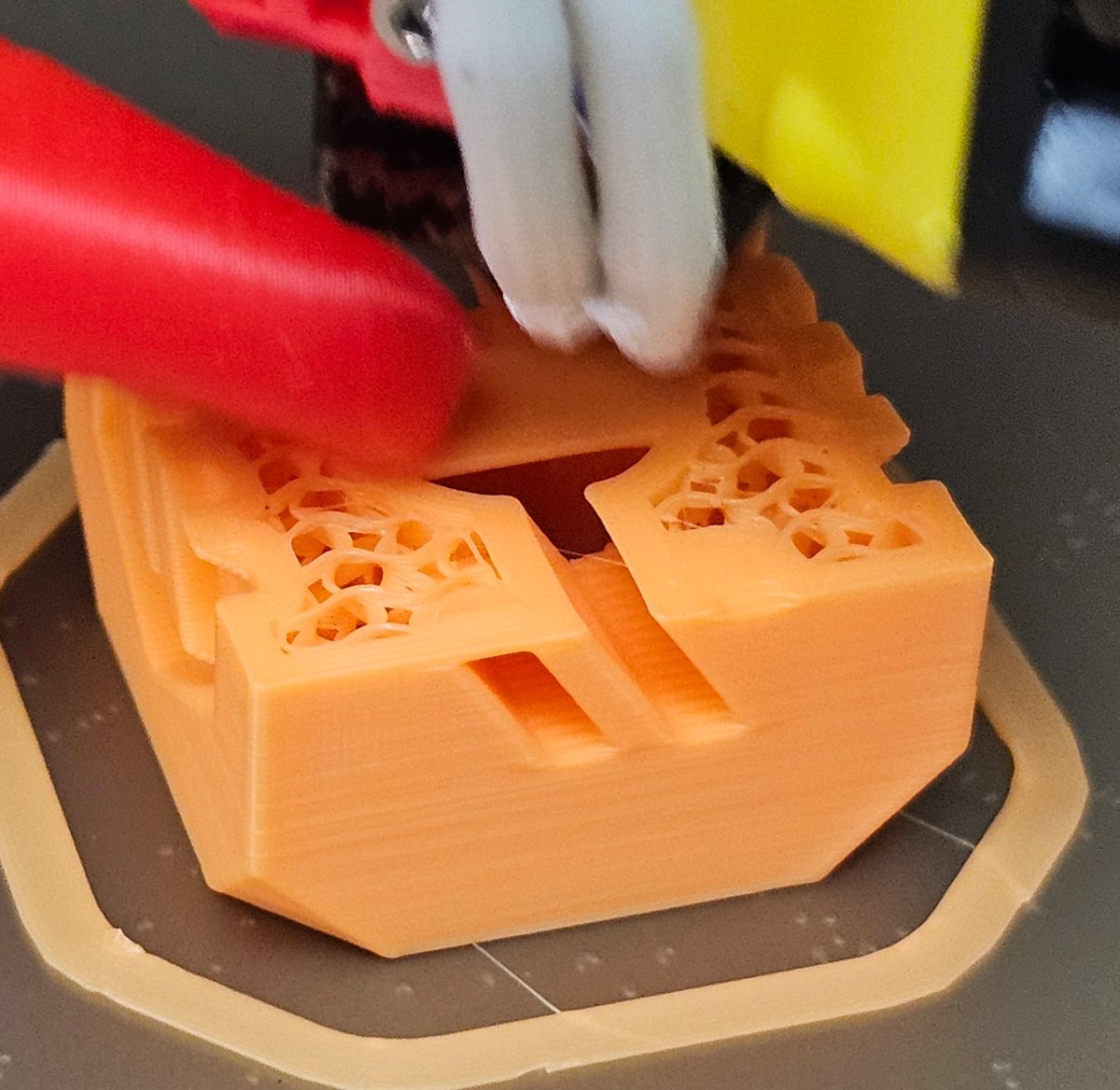
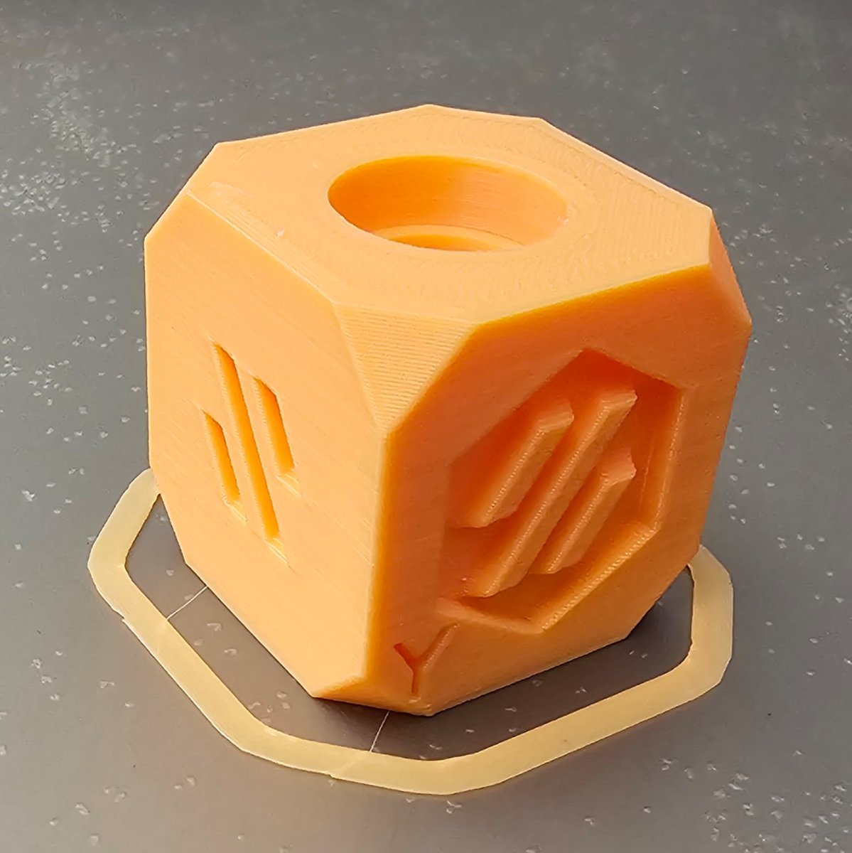
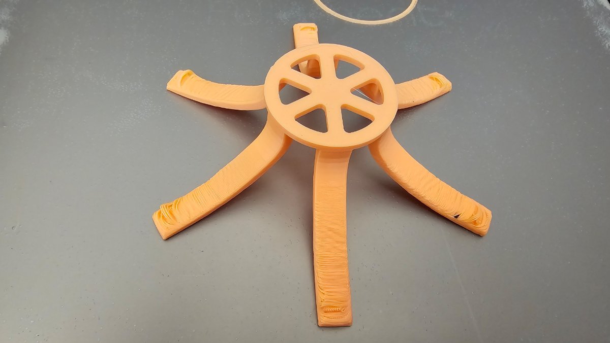
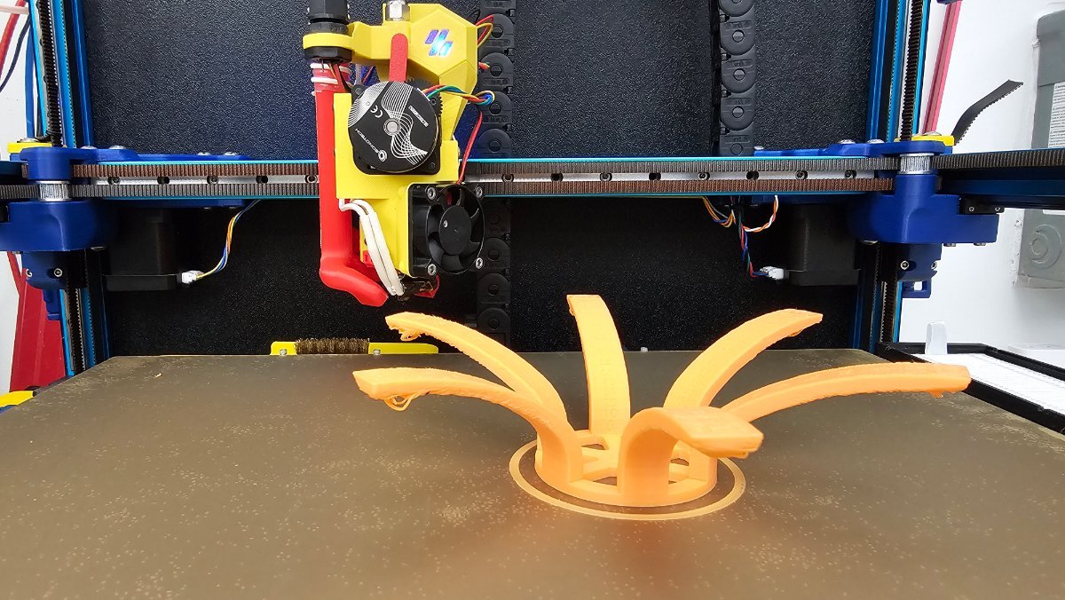
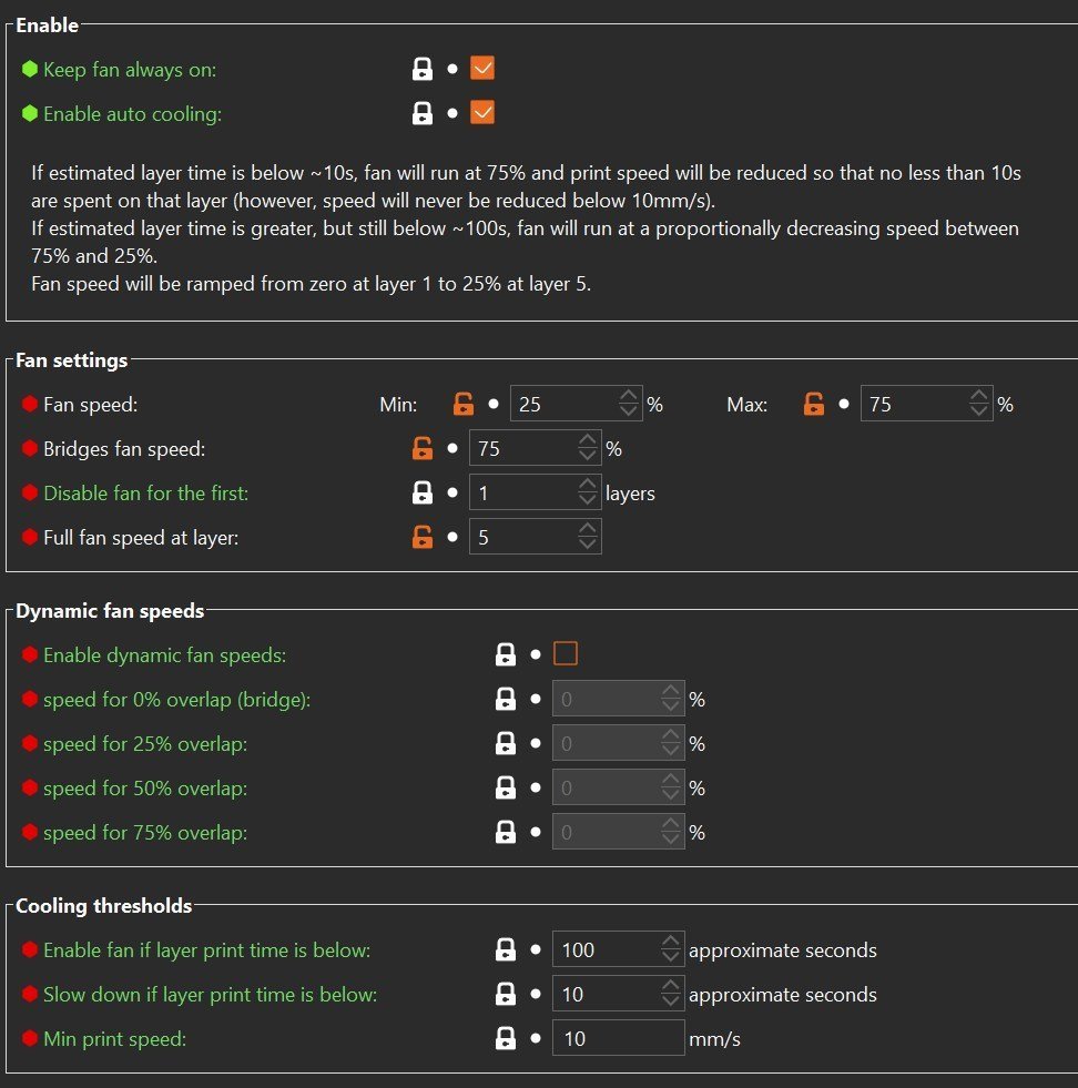
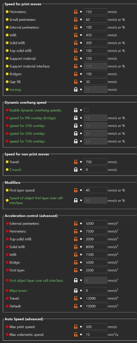
Today, I re-run the Larger Overhang Test Print and I got some very surprising good results! I modifed the PrusaSlicer Speed and Filament Cooling settings as seen below and actually it printed everything to 90 degrees overhangs, with some drooling at 85 degrees!! The quality of the bottom started degrading around 70 degrees; see photos.
2 points
-
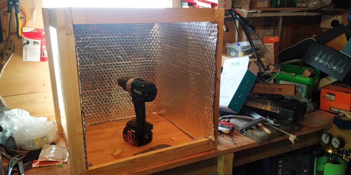
Thanks guys, made some progress on the box last night. Please excuse the mess, I need the sort out all that crap. It used to live out of shot, where the 3d printer has moved in! Plan is to put foam board insulation into the top and sides, external to the foil, and then finish it with 6mm ply shell, as i some have some of that laying about too. Might get the wallet out for some beading to tidy the edges My thinking with it is to obviously have a door, but also be able to is just lift it off over the top of the printer, to allow for easy maintenance etc.
2 points
-
@3DCoded: I'm embarassed to admit that I did read that discord post, but I blew past it because I totally forgot that the [probe] section was now in an [include...] file, exactly as Sineos described. Wouldn't be the first time he's figured into the solution with an issue I've had! Much appreciated!2 points
-
2 points
-
UPDATE Unless some major issue arises, the toolhead is done! The only items that are not addressed yet is the rear cables with the EBB36 board cover, and the nozzle lights.
2 points
-
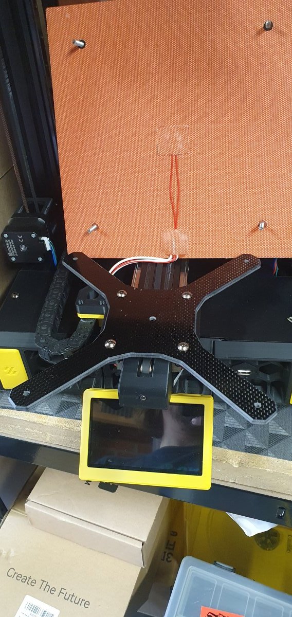
I cut a carbon fiber y carriage today, its 114g :), about 132 grams lighter than my old cut down ender axis. I also released I had some little paper washers under the bed spacers, took the two out from the front and the range has reduced from about 1.1mm to 0.3 :).... Happy with that.
2 points
-
For anyone considering using the Bontech INDX when released in a Trident, I found this system for the Lineux system, but it could also be adapted for the Bontech. There is no STL, but you can generate them from the step file. Link
2 points
-
Hi guys! My two Vorons are a LDO V0.2r1-S1 and an Enderwire conversion, both of which are in-progress, with the V0.2 running for the most part, but I'm making more upgrades to the tool head and adding mods before it can start printing. The Enderwire is stuck in a weird place. It's basically all done and technically runs but I have some trouble nailing down it's Klipper config, and I'm deciding on a probing solution for it. I have a BTT Eddy and multiple cartographers laying around, but I'm also open to other suggestions if you have any other good suggestions. I also own other non-Voron printers, those of which are a Qidi Tech Q1 Pro (currently mid-modding and needs some TLC), an Elegoo Centauri Carbon, Bambu Lab A1 Mini, and I'm also in the middle of building an E3NG by RH3d. As you can see, I'm in the middle of a bunch of projects and I'm just really waiting for parts at this point before I can finish any of them. Happy to be part of a new community, Cheers!2 points
-
In the videos, they're running on Klipper.2 points
-
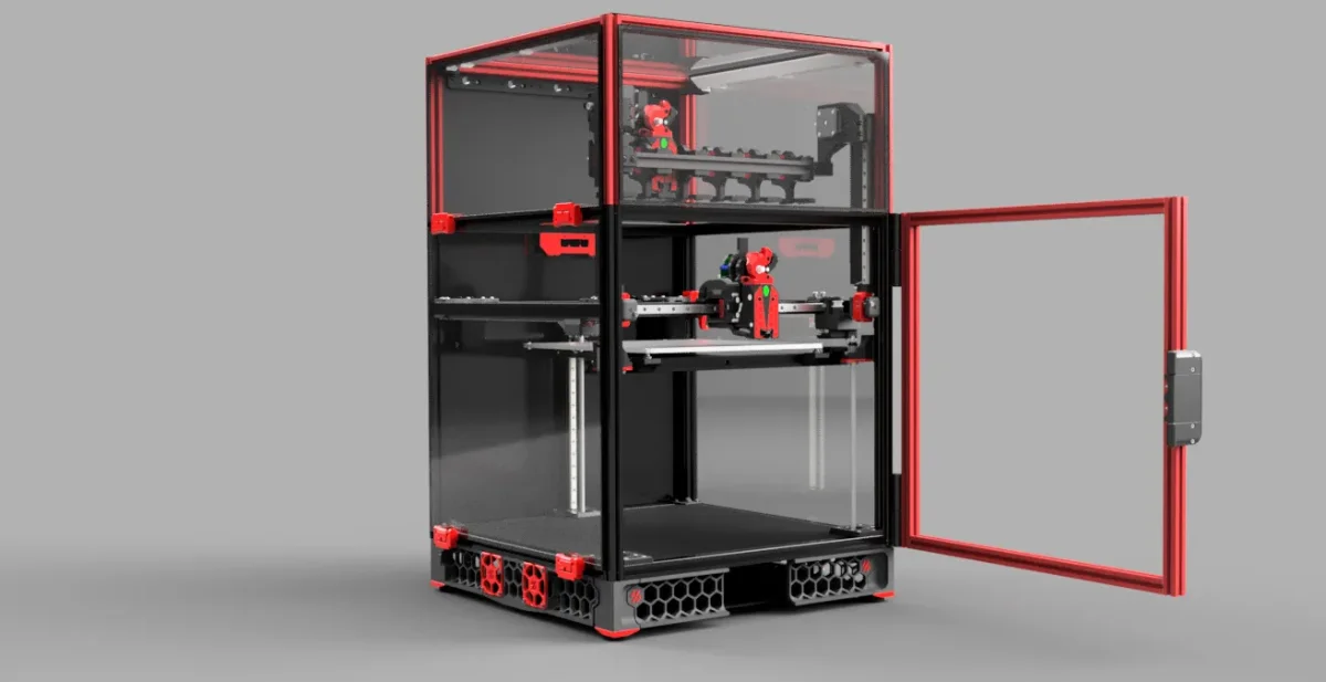
You said it; rabbit hole! It looks like a great idea and without having tried it looks more robust than a filament changer (ERCF, AMS etc.) and all shortcomings; complex and finicky mechanism for loading/unloading filaments, filament waist, filament loop holding area etc. True IDX systems will be faster and maybe more flexible, but difficult to DIY and implement more than 2 heads, and you will need multiple full heads (extruder, heater, temperature sensor, fan(s) etc.) which is more complex and high cost. Looking forward to the final product. Personally, I like Bonctech products as my original LGX never missed a bit and now the LGX Light V2 works as good!2 points
-
Looks so good! Rabbit hole - fill it up fill it up !2 points
-
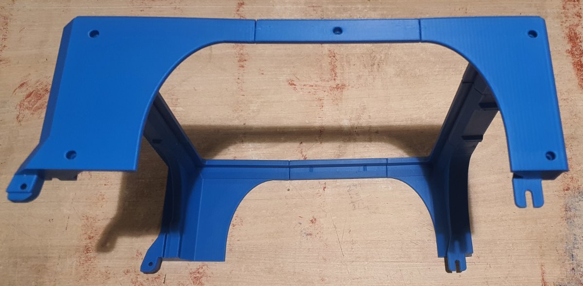
I am finally getting back to this project! This has been my go-to printer for the last year but using it has shown me several points for improvement. I am adjusting the frame and tophat as well as the gantry. I am also applying my new rigid Mini Stealth cores to this printer but I may need to create new rigid x-carriages specific to the new Vorpal gantry design. I will validate the new design by building a 120mm version and then add the two variants to the GitHub repo. Hopefully I can find a Send Cut Send service in the EU for the panels so that I can get an idea of the pricing and see how the typical build experience would be. Then, I really need to buckle down and get the assembly manual finished..
2 points
-
My wife asked me why I was so excited. I showed her this. She couldn't care less. I know you guys here will understand. LOL
2 points
-
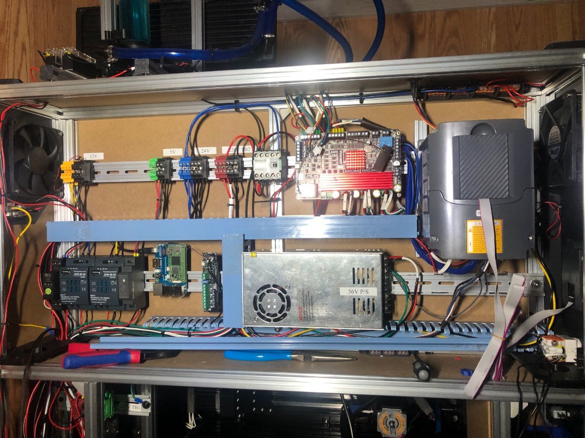
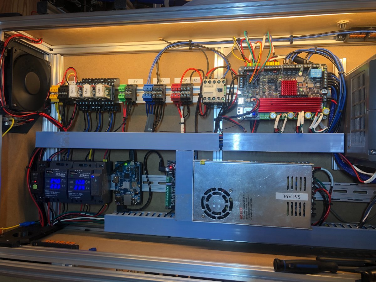
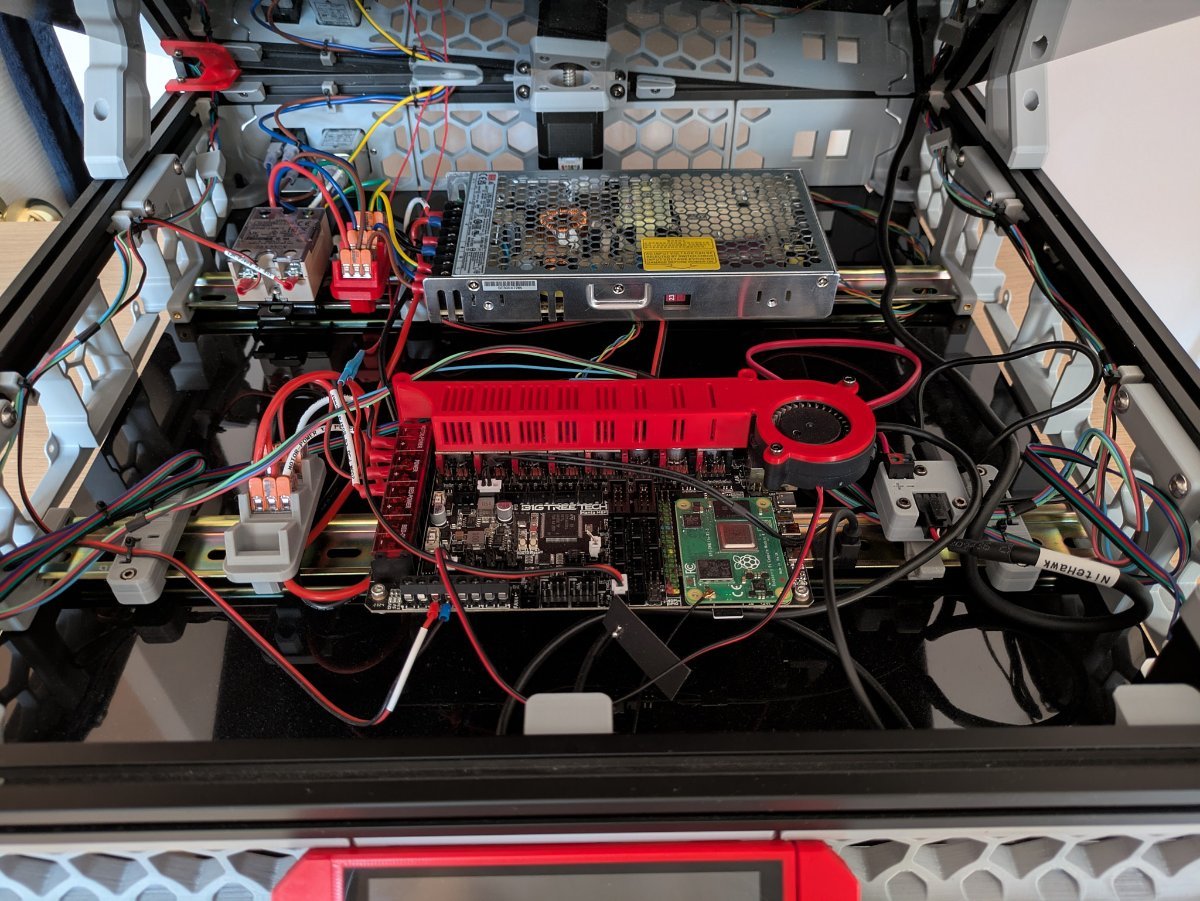
Progress on rewiring the Casa enclosure, 95% of the wires connected.
2 points
-
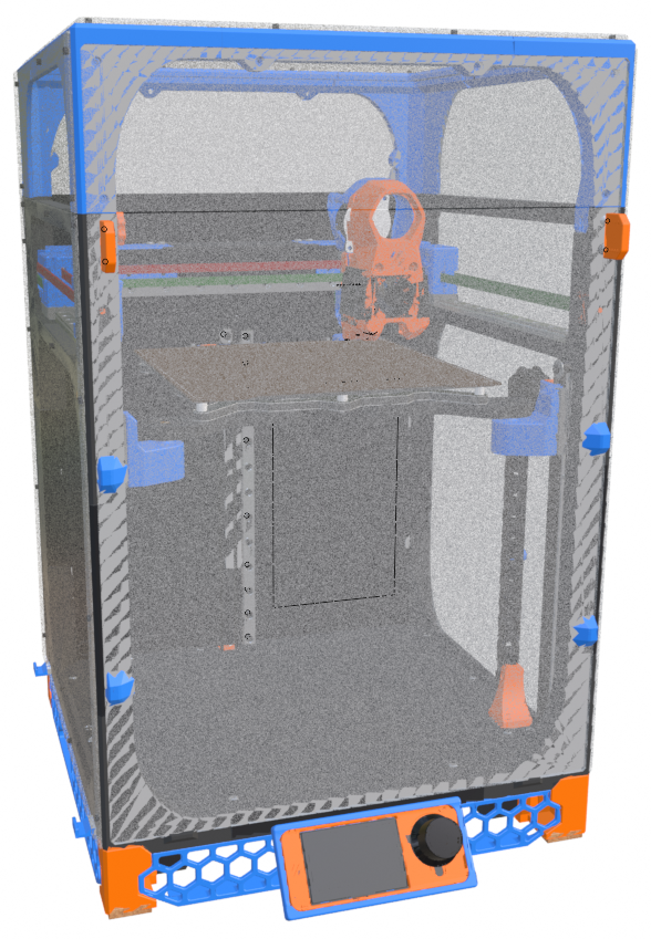
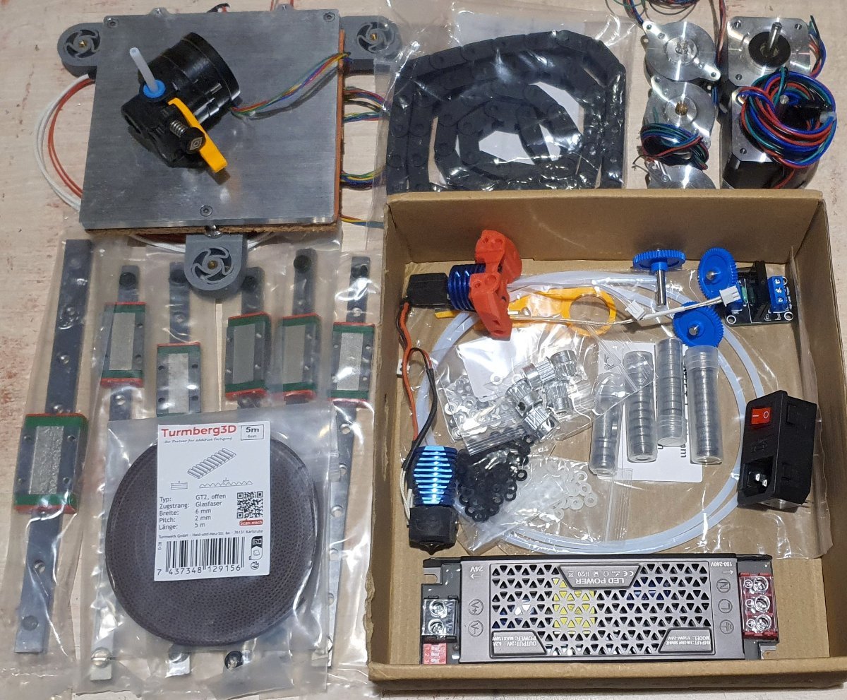
Got some new parts. 24V is cool but 2.8A rms steppers need more pauwa to get more speeeed. Non floating boat will print fastaa!!) I’m going to 48V setup also I’m currently busy at insulation, think about to use tempered glass in metal frame. The most tricky part is back vertical profile, it moved out about 25 mm to maximize print area
2 points
-
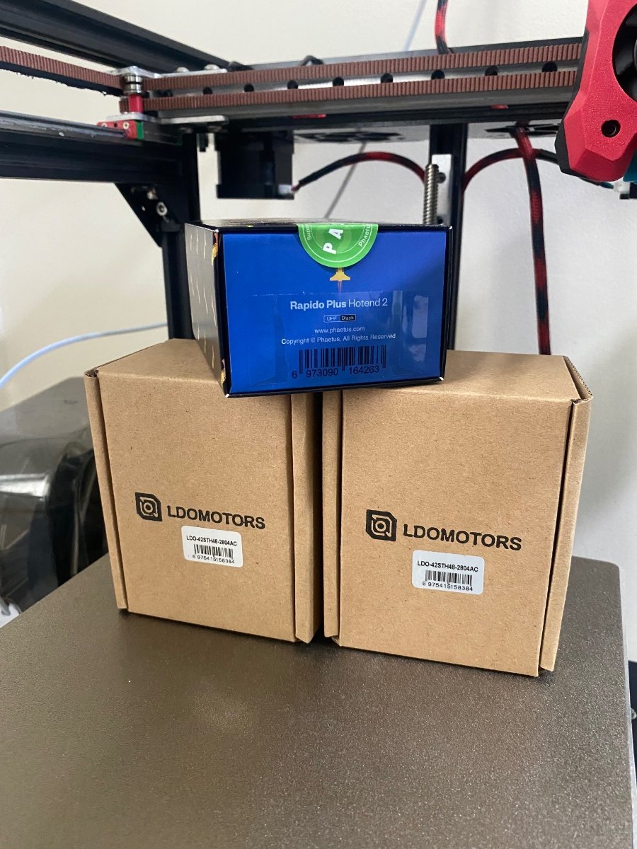
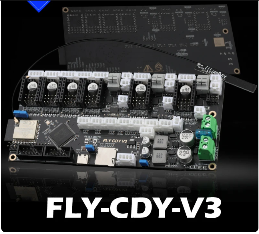
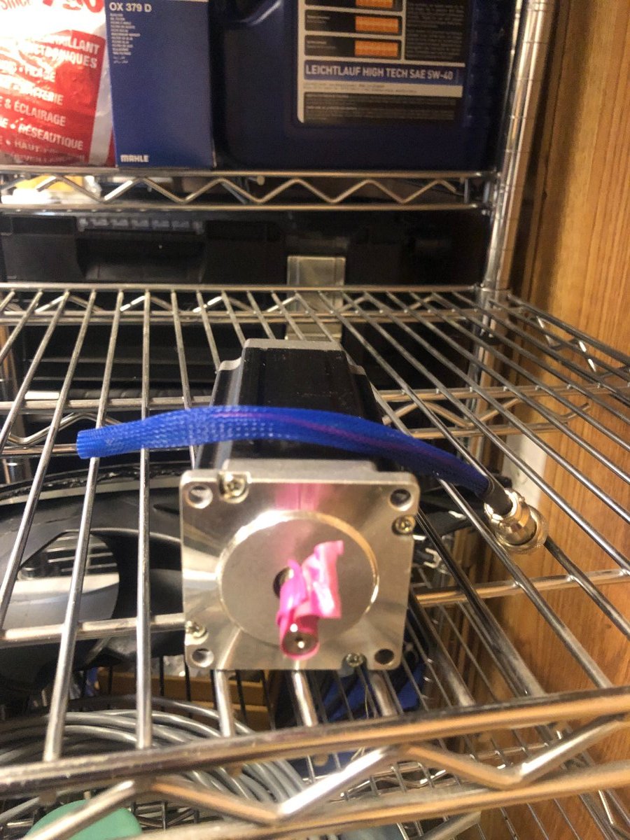
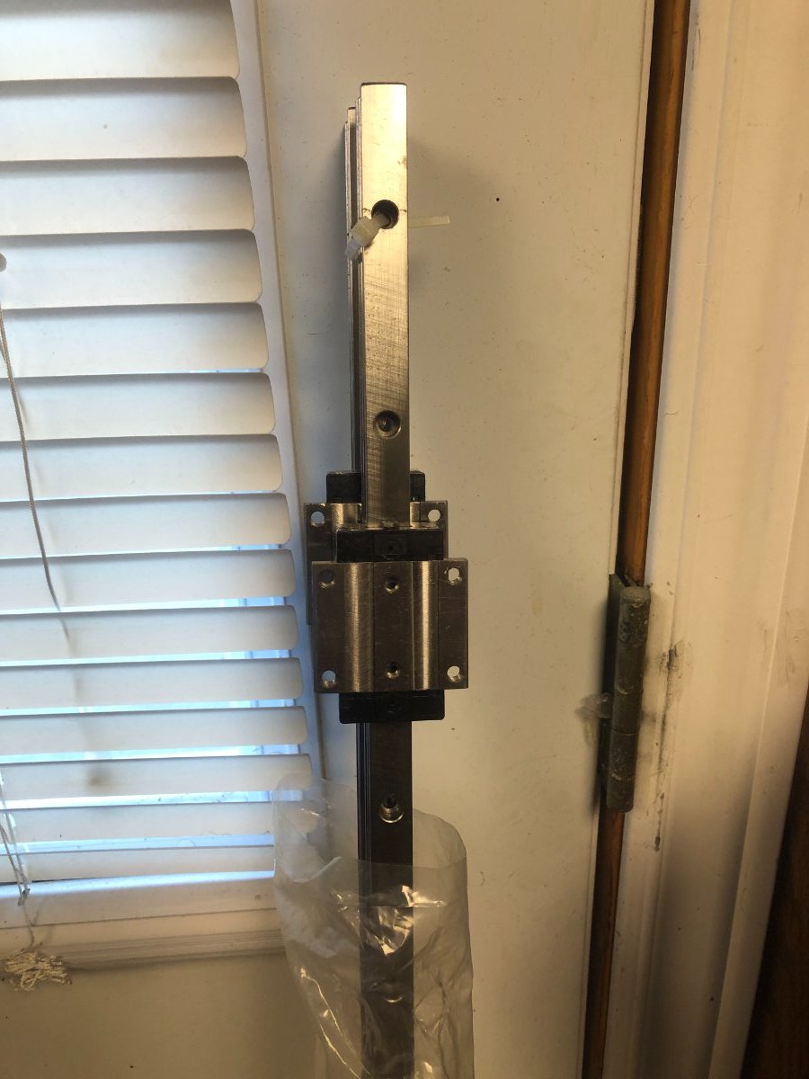
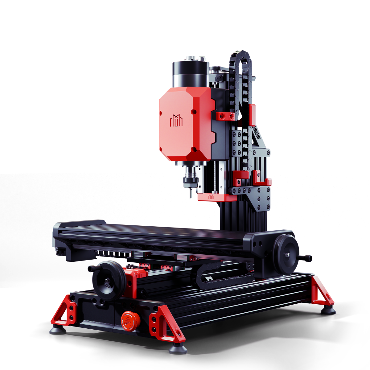
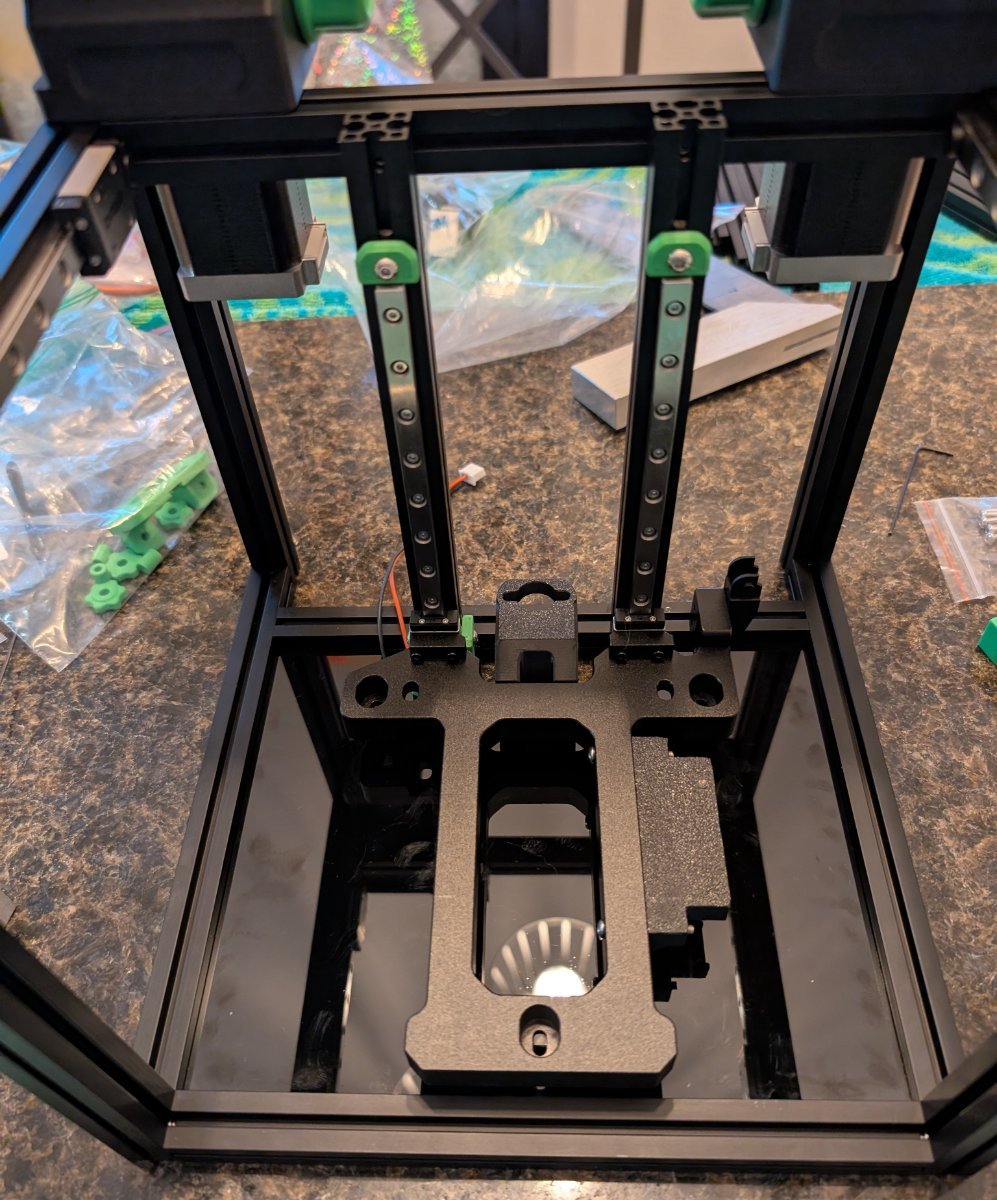
Milo V1.5 CNC Bench Mill Github Link Not a 3D printer but still going to be an interesting build The idea is to eventually make parts to replace the printed parts on the mill and for the Trident and V2. This is going to be a slow build, I'm self-sourcing the parts and will assemble them as parts are purchased and arrive. Years ago I purchased some parts to build a CNC machine but never completed the build. The frame and spindle were the last items to be purchased and built. Since then electronics for CNC have come a long way specifically the stepper drivers and motherboards. I already have the Nema 23 stepper motor but are larger than the suggested spec for the build. I'll be testing them with the Mellow 32bit FLY-CDY V3 Wifi Control Board when it arrives. These are the steppers I'll be testing: I have these Hiwin HGR 15 linear rails which I can cut to length, the blocks don't match the printed parts, but I can either modify the printed parts or order new blocks. The blocks alone will cost the same as purchasing a complete set of rails. The advantage of using Hiwin rails is the pre-load. Appreciate the lesson on the basic use of Fusion 360 that @Penatr8tor was kind enough to give me on Zoom. Parts ordered: Mellow Fly-CDY-V3 Complete Fastener Kit 2 x 4010 24V. Fans
1 point
-
I figured out the issue from last night.. lol.. when all else fails check the motors, even when new. I swapped out the motor from the side that was not moving correct distance, its now working. Next.. Need to get endstop working1 point


.gif.60a049296a577eef1104c072e035716f.gif)