Search the Community
Showing results for tags 'v1.8'.
-

Version 2022.03.31
14,798 downloads
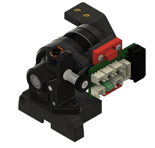
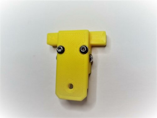
Orbiter 2 Clockwork Module (beta) This Clockwork module allows the use of the Orbiter v2 Extruder in the Voron Afterburner. THIS IS A PRE-RELEASE - DO NOT DOWNLOAD UNLESS YOU ARE WILLING TO DEAL WITH POSSIBLE ISSUE OR TO GIVE FEEDBACK! The rear screws that hold the chain anchor on are m3x8, two of them. They use the Voron heat set inserts, m3 I was working with DoubleT on the PCB holder. Trying to build a universal tool version so we could use different holders.- 83 comments
-
- 20
-

-

-

-
- orbiter2
- spacelab2021
- (and 4 more)
-
Version 2022.04.03
231 downloads
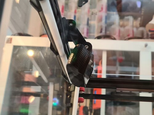
Important Notes Hello everyone, Here is my C920 camera mod, please follow the disassembly guide below to remove the current mount off the camera. Please keep the 4 bottom screws from the mount as you will need them for my mod. Instructions For Disassembly Found Here! This mod allows you to set 2 point position for your camera, BOM Qty Item 2 M3x40mm 1 M3x10mm 2 Nuts 1 M3 Hammerhead nut https://camo.githubusercontent.com/758a4b22a5c56662c568b7ffb24373659bc0266bcc721e882b16ef4f2bb51f16/68747470733a2f2f7777772e70617970616c6f626a656374732e636f6d2f656e5f55532f692f62746e2f62746e5f646f6e6174655f4c472e676966- 1 comment
-
- 3
-
-
- psychoshaft
- v1.8
- (and 2 more)
-
Version 2022.05.03
374 downloads
Stealthburner Clockwork1 PCB Cover I designed a cover for users who are still rocking the CW1 with Stealthburner, with the same low-poly esthetic of stealthburner. This cover is a snug fit, so please make sure your wiring is all nice and tidy or you could have some issues.- 6 comments
-
- 16
-
-
-
Version 2022.08.30
368 downloads
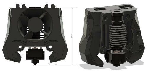
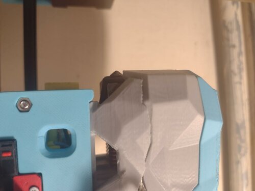
Stealthburner (RC1) Crazy Dragon Fan Duct With special thanks to @chestwood96, sponsored by @3dmellow for the Crazy heatblock, as well as the awesome base design from the VoronDesign team, I'm able to create the Stealthburner Crazy Dragon fan duct. The fan duct is designed based on the Rapido toolhead mount (RC1), retro-fitted with Dragon styled duct allowing wind to blow towards the throat only. The duct is designed to be able to mount the Phaetus/Triangle Lab dragon heatsink with Mellow Crazy Heatblock (verified by myself and @chestwood96) Phaetus Dragon UHF mini (standard UHF version without the melt zone extender) TriangleLab T Volcano (to be verified) Print Parameters Print in standard Voron settings. Previews -
Version 2022.08.16
1,641 downloads
Magnetic Panels with Magnet Inserts There are various panel latches and magnetic clips that offer quick panel removal for swapping between enclosed- and open-chamber printing, but I wanted to fix a few of the pain points that I ran into with some of the existing mods. Does not require a lot of filament. The corner and mid-panel clips were modeled after the stock Trident panel clips and are similarly hollowed, saving filament and print time. Uses a thin strip of VHB to adhere to the panels. This should provide (1) solid adhesion without the need for drilling or extra fasteners, (2) some amount of squish for the magnets to pull against, and (3) the ability to adjust or remove them in the future. The frame magnet inserts are designed to (1) require only printed parts and no additional fasteners aside from the 6x3 magnets, (2) sit inside the frame slot flush against the aluminum frame face, (3) be easily adjustable, and (4) retain the magnets without glue and allow removal for correcting polarity or salvaging. Discord@PF VT.520 came up with the idea of using a hammerhead-style rotating nut to tighten and press against the magnet insert, holding it in place. There are two included versions of the inserts. Magnet-Insert.stl is the original design but may be slightly more difficult to print due to the bridging involved. Magnet-Insert-Side.stl is redesigned for easier printing; namely, reoriented on its side, uses 45° chamfers rather than fillets, and does not require bridging. The panel's ability to sit right up to the face of the frame allows the panels to pop on and off without any interference. The only required parts are a small amount of VHB tape and a lot of magnets (48 6x3mm magnets for each panel). Magnet inserts hold two 6x3 magnets and is held in the aluminum extrusion with an unhammer The corner and mid-panel clips hold matching 6x3 magnets Installation jig makes it easy to set the proper spacing for corner inserts -
Version 2022.01.21
216 downloads
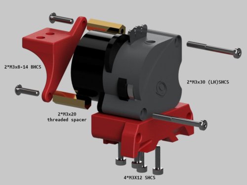
A mod to mount the LGX Lite to the current X carriage. Additional Hardware: LGX lite mount 4* M3x12 SHCS don't forget to install the included nuts with the LGX lite into the extruder housing. 4* heatset inserts Chainmount: 2* M3x30 SHCS low head to match the originals but regular work 2* M3x20 threaded spacer 2* M3x8-14mm BHCS length isn't critical as long as it's between 8 and 14mm 2-3* heatset inserts Installation: Install heatsets into printed parts. Remove the motor and install the nuts included with the LGX. Attach the LGX to the mount. Reattach the motor using the longer screws. Thread the spacers on the exposed screws behind the motor. Screw the chainmount onto the spacers. Attach to the carriage. -
Version 1.0.0
720 downloads
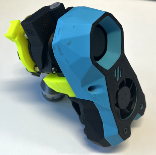
StealthOrbiter This mod aims to mount the orbiter V2.0 extruder to the stealthburner assembly. In addition, it incorporates the Orbiter filament sensor to enable support for the ERCF. There are a number of different versions, depending on your configuration: Standard mount Standard mount, with PG7 cable gland Filament sensor mount Filament sensor mount, with PG7 cable gland The most up to date files can be found on the github repo Acknowledgments - spacelab_2021, for providing the starting point I used in developing this mod- 15 comments
-
- 16
-
-
-
Version 2023.01.20
98 downloads
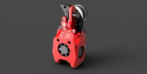
MiniSB Sharkfin Modified the MiniSB toolhead to accomodate the Sharkfin extruder. -
-
Version 2023.01.19
143 downloads
MiniSB LGX Lite A Bondtech LGX Lite variant of the MiniSB -
Version 2022.09.23
96 downloads
LGX stealthburner connector cover This is a remix of craxoor's Afterburner PCB Cover designed to work with the Stealthburner and Bondtech's LGX Extruder.- 1 comment
-
- 3
-
-
- sammynorway
- v1.8
- (and 3 more)
-
Version 2021.08.22
332 downloads
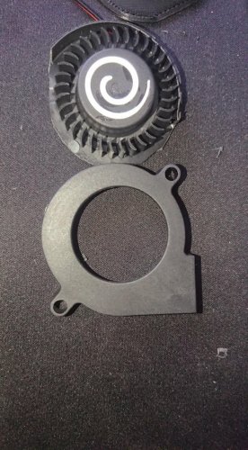
LoudOwl aka Stabby This is alternative part cooling fan solution which uses dual 5015 fan setup for Afterburner Toolhead. Replaces original parts that house 4020 fan or any other similar type of mod. This mod is more of situational add on for PLA or similar type filaments which might require a lot of cooling (or printing at super high speeds). It is not constant solution as it increases gantry weight. Hardware 2x 5015 24v fans 1x M3x20 SCHS (DIN912) Printing There are two sets of STLs. One with inbuild supports and one without (for those who trust their slicers autosupports). Tested with recommended settings for Voron parts: 4 perimeters, 5 tops/bottoms, 40% infill. Though it is possible to use less plastic to reduce weight of plastic parts: 3 perimeters, 3 tops bottoms, 15-25% infill. Both versions of STL were tested by printing and assembling !!! Assembly First print out- 2 comments
-
- 1
-
-
- baltojikale
- v1.8
- (and 2 more)
-
Version 2022.05.09
826 downloads
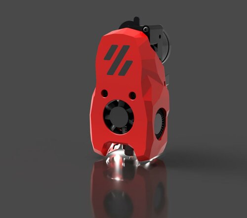
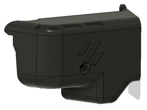
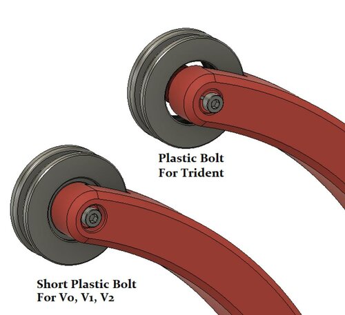
Horseshoe Spool Holder This is a method to mount the filament spool inside the enclosure of a Voron Trident 3d printer, or outside a V0, V1 or V2 printer. It works with 200mm, 1kg spools only. For mounting internally in the Trident, the ptfe tube is installed as shown: up through the gap in the side of the rear extrusion. Alternately you could drill a 4mm hole though the B stepper mount top and bottom parts. To install the spool: Feed the filament through the ptfe first, then align the spool into the front and top bearing rings, and pull forward to spring the frame and drop into the rear bearing ring. BOM: 3 608 bearings (any type) 2 M5-8mm (pan/socket) head bolts and 2 M5-Tnuts for 2020 extrusion only OR 4 M3-8mm (pan/socket) head bolts and 4 M3-Tnuts for 1515 extrusion 3 - M3-8mm bolts (pan/socket) Internal Version for Trident only Print PlasticBolt(x3) and use a m3-8mm PH or SH bolt to secure the pin in place. External version for V0, V1, V2 Print ShortPlasticBolt(3x) and use a m3-8mm PH or SH bolt to secure the pin in place. Please provide feedback for issues/suggestions to #Logan2225 on VoronDesign Discord. Thanks!- 9 comments
-
- 12
-
-
-
- LoganFraser
- v0
- (and 3 more)
-
Version 2021.10.09
439 downloads
Afterburner LGX Useful links, info, and models for using the The LGX™ Large Gears eXtruder with Afterburner... Afterburner LGX Mounts Klipper config Extra LGX Models LGX Cable Cover LGX Gear Cover LGX Lever Cover Afterburner LGX Mounts Mounting the LXG to AfterBurner requires some additional mounting plates. You will need both of @Nemgrea's mounts from Discord: lgx_AftB_Mount_Front.STL (Discord file link) lgx_AftB_Mount_Rear.STL (Discord file link) These models are pinned in the #voronuser_mods channel on Discord, and can be found in this message. Thanks to @Nemgrea V2.199 V0.000 and the crew for their efforts designing and testing the mounts, and offering them to the community. Aside: For my own build, I found that my third-party M3x20 screws had a large enough head that the toolhead couldn't mount to the X Carriage assembly properly without a bit more clearance. If you find yourself in this situation, this mod of @Nemgrea's mount is nearly identical to the one on Discord but with slightly more clearance for the bottom screws. Please try the (semi)official one first before using this mod Klipper config Bondtech has some official documentation for configuring Klipper here. Below is the configuration I am currently running. rotation_distance: 8 microsteps: 16 full_steps_per_rotation: 200 # use either # gear_ratio: 44:14, 37:17 # rotation_distance: 55 # or # rotation_distance: 8 # but not both! The either...or warning is not from Bondtech, but provided here to honor the memory and sacrifice of my first hotend and save those that may come after from suffering the same fate... Extra LGX Models LGX Cable Cover Besides the mounting parts, most people end up asking about a cable cover. There are a few posted around Discord, but after seeing Craxoor's PCB cover I designed a similar cover from scratch for use with the LGX. Note that this cover does not work with the toolhead PCB - it just looks similar. lgx-cable-cover.stl (Cereal not included) LGX Gear Cover A little cover for the Large Gears on the LGX so it doesn't chew through the fan wires. lgx-gear-cover.stl LGX Lever Cover Drop-in replacement for the filament pre-tension lever, in case you want a different color: lgx-lever-cover.stl- 6 comments
-
- 6
-
-
-
- geoffreyyoung
- v1.8
- (and 3 more)
-
Version 2022.03.16
470 downloads
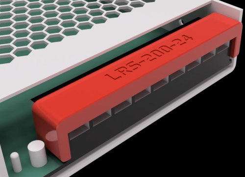
LRS Screw Terminal Cover Designed to cover the screw terminals for several LRS style PSUs. Other Meanwell PSU may work. Feel free to ping me in discord to add to the compatibility list below. Pro tip: These are very snug to the point it will bow. This is intentional as it was designed to take some effort to take off. Printing Default voron settings No supports needed Compatibility List LRS-50 LRS-200 -
Version 2022.10.13
18 downloads
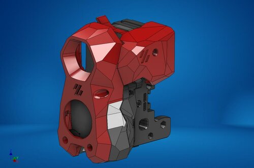
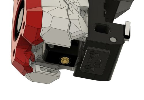
Zodiac BMO Stealthburner Toolhead A modified toolhead for use with the Zodiac BMO Hotend and compatible with RC1 of Stealthburner. It was created from the original RC1 Stealthburner Phaetus BMO Toolhead files. If changes after RC1 of Stealthburner make this mod incompatible, I will provide updated files based on the official Stealthburner CAD files. The official Zodiac3D CAD Model of their BMO Hotend was used for reference. Images Notes For optimal fit it is very important that your printer's dimensional accuracy is nearly perfect. Especially Pressure Advance has to be tuned right. Even then it is still a very tight fit, when putting in the hotend. That ensures that it cannot twist or wiggle. One handed nozzle changes should be possible, but are generally not recommended. The bowden tube length from top of the toolhead to the heatbreak of the hotend is around 31.2mm. Take that into account when calculating the total bowden length. (E.g. Clockwork2 needs 11mm above the toolhead, so that accumulates to a total bowden length of 42.2mm, when using Clockwork2.) Test prints were made with standard ABS, ABS and ASA Carbon. -
Version 2022.11.09
157 downloads
Stealthburner Clockwork2 Toolhead for HF Crazy Mozzie This is a a toolhead mount for the HF Crazy Mozzie (or other Mosquito clones), compatible with Stealthburner RC1 and Clockwork 2. Design source. The airflow pattern is designed and tested for the high-flow version. Here it is shown with the regular version: In action: -
Version 2022.05.09
877 downloads
Rear Umbilical Addon and Y Endstop Relocation BOM Pieces M3 Heatinsert 4x M3x10 SCHS 4x since my a/b motor mounts are MJF single pieces i needed a way to add umbilical compatibility without the need to reprint anything. so i designed this. its however heavily based on Selliot79's Design. i just designed it to be a bit smaller, to fit a IGUS CF5.05.18 perfectly and moved the mountings to the rear, so theres space for a Y Endstop relocation -
Version 2022.04.06
149 downloads
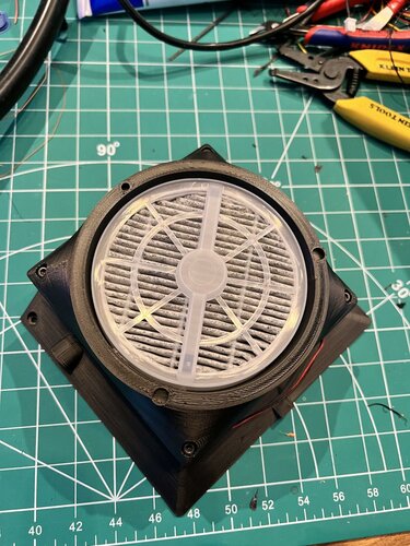
HEPA Filter Exhaust for Voron 1.x/2.x I've designed a new exhaust which uses a 120x120x25 mm fan and HEPA filters (compatible with MELEDEN, RIGOGLIOSO, JINPUS and LTLKY air purifiers). This is a direct replacement for the stock air exhaust system. Configured in Klipper to power the fan at 50%, and coupled with the nevermore micro, this seems to add to negative air pressure in the chamber and have a noticeable impact on reducing fumes, while only reducing chamber temperature by a couple of degrees C at the exhaust port. Bill of Materials New Parts 1x 120x120x25mm fan such as Noctua NF-F12 iPPC-2000. (note that I have an adjustable voltage on my control board, but make sure your fan matches the voltage for your system.) HEPA Filter such as Nispira True HEPA Filter Replacement with Activated Carbon Parts from Voron BOM Parts here are already listed in the Voron 1.x (Trident)- 4 comments
-
- 5
-
-
-
- deprintinator
- v1.8
- (and 3 more)
-
Version 2022.09.23
216 downloads
Creality toolhead for stealthburner. Not recommended but a potential pathway for e3- -
Version 2022.09.10
1,225 downloads
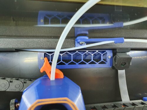
PTFE Bowden Tube Guide and Canbus Wire Support Required Hardware: M3x8 Bolt and M3 T-nut M5x10 Bolt or a M5x8 Optional 4mm drill bit for cleaning out bowden tube path About In my 350 build the PTFE tube kept getting caught so I made this arm to keep it up. The shorter arm works better so I recommend using it instead Install Drill out bowden guide with 4mm drill bit for a perfect fit (optional) Bolt mount to rear frame with M3x8 and tnut putting the lip at the top Screw arm on with M5x10 (I used a M5x8mm and it works fine) into the plastic allowing the arm to still be able to swivel -
Version 2022.08.16
379 downloads
Runout UnKlicky Sensor The Runout UnKlicky Sensor is a filament runout sensor that can be used to pause a print if printing filament breaks, runs out or otherwise is no longer present in the sensor. The design uses magnets as the switch, making it easy and cheap to source BOM components. Printing: Components: 1x Pin.stl 1x Roller.stl 1x Base.stl (different options are available[*]) 1x Top.stl (different options are available[*]) Printer: Use the Voron defaults and print in ABS or better The parts are orientated correctly in the STLs [*]Base and Top: There are 3 bases and 4 tops to choose from: Bases: Base.stl is the standard base with push in holes for the PTFE tubes Base_PC4-M6.stl which allows the use of PC4-M6 connectors for the PTFE tubes Base_Collet.stl which allows the use of E3D M4 collets Tops: Top.stl is the standard top with no mounting options Top_2020.stl provides mounting to 2020 extrusions using a t-nut Top_1515.stl provides mounting to 1515 extrusions using an inserted nut Top_1515_NoNut** provides mounting to 1515 extrusions if you have no inserted nuts available [**] The Top_1515_NoNut can be used if you don't have any free nuts. It snaps into the extrusion. If it moves or slips, you can use a M2x10mm self-tapping screw to secure the sensor to the extrusion. Do note that the screw can scratch the inside the extrusion if that might bother you. BOM: 5x M3x8mm SHCS/BHCS (2x for the wired screws, 2x for the top/base, 1x for 2020 extrusion mount) 2x 6x3mm neodymium magnets (for the switch) 1x M2x10mm (optional for 1515 extrusion mount) 1x M3 Hammer T-Nut (for 2020 extrusion mount) 2x fork connectors (optional - for attaching wires) Assembly: Parts used: Insert one of the magnets into the pin, push it in fully so that it shows in the groove gap: Insert the corresponding pin into the base and make sure that they attract from the outside as shown: Insert the pin into the base with the pin grooves to the sides for the screws to enter. The pin should be pushed down to the bottom by the magnet in the base. Push the pin right up to the base magnet and screw in the screws to either side of the pin: Place the top on the base and secure with two screws: Attach cables to each screw that goes into the pin. There is no polarity and no voltage so it doesn't matter how they are connected. I used fork connectors for ease of use. Make sure the pin screws are screwed in tightly: Hook up the wires to a multimeter and put it on it's continuity test. It should show resistance (and/or beep) when there's no filament in the sensor: It should show no resistance (and/or remain silent) if you fully insert some filament into the sensor. Feed the filament through a few times from each side to ensure that you do not see any resistance when filament is present, and that you do see resistance when there is none: Wiring: Wire to an end-stop or similar pin. Do not connect to voltage, only to pin and GND. For example, with the BTT SKR MINI V2.0 you could use the E-STOP pin (PC15) and GND. For the BTT SKR Pico you could also use the E-STOP pin (gpio16) and GND. Klipper: A simple configuration is available in this repo. Upload and include runoutunklicky.cfg in your printer.cfg and change the PIN definition to the one you chose on your MCU. The config file contains what is required to use a runout sensor, but it will only literally pause the machine and resume when prompted. To have the toolhead parked away from the print to an accessible place to change filament, implement one of the following examples in your klipper configuration: AndrewEllis93 Mainsail Test by inserting and removing filament. If it shows incorrectly in klipper add a ! in front of the PIN definition and test again. Credits: Thanks to: chestwood96 for inspiration from the UnKlicky probe for SlideSwipe majarspeed for the Unklicky probe jlsa1 for the Klicky and Unklicky probes al3ph for the -
Version 2021.10.01
774 downloads
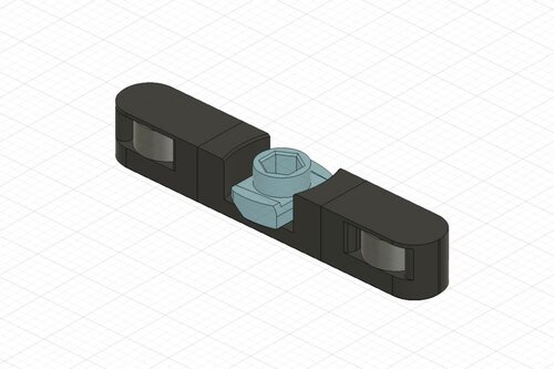
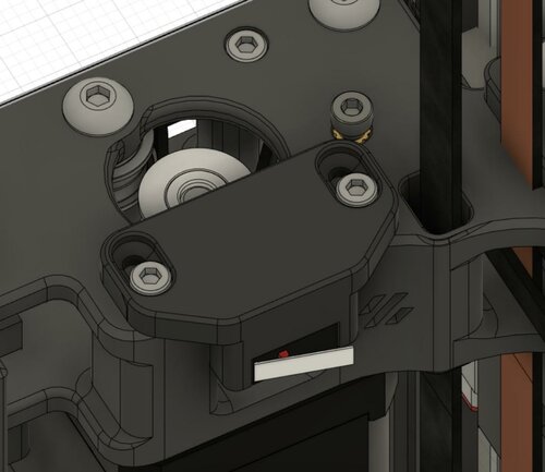
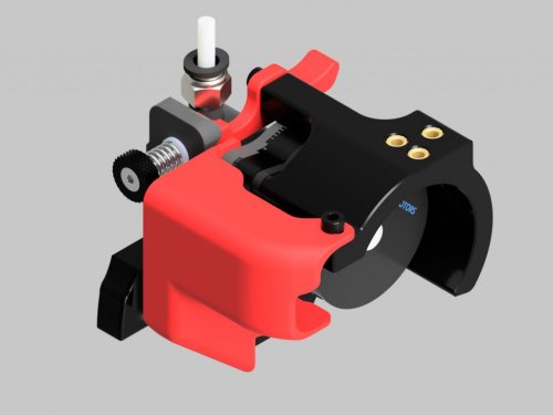
Orbiter Clockwork Module This Clockwork module allows the use of the Orbiter v1.5 Extruder in the Voron Afterburner. Features One of the main issues I observed when using the orbiter was a lack of a quick filament release in addition to a lack of a suitable clockwork adapter that would swap an orbiter directly into the Afterburner ecosystem. Many of the issues observed were addressed with this Clockwork Module. This version provides a chain anchor for the Voron 2.4 and the Switchwire, a Cable Cover, and a quick filament release lever. Bill of Materials (BOM) Quantity Name Type 1 Orbiter v1.5 Extruder Orbiter Thingiverse link Hardware 9 M3 Heat Set Inserts McMaster Link Hardware 94180A331 or suitable inserts (Thread Pitch 0.5, Installed Length 3.8mm, Diameter ~5mm) 1 M3x8mm SHCS Hardware 1 M3x16 SHCS Hardware 2 M3x20 SHCS Hardware 1 PTFE 45mm (Dragon) Hardware 1 Clockwork Adaptor - Front Printable 1 Clockwork Adaptor - Back Printable 1 Cable/Connector Cover Printable 1 Filament Quick Release Printable 1 Chain Anchor (Version for Voron 1.8/Trident/2.4 and Switchwire) Printable Assembly Guide Orbiter Clockwork Assembly Guide Orbiter Clockwork Module Images Release History Version 1.0 Orbiter Clockwork Adaptor has been verified to fit and function on a Voron 2.4 and a Switchwire. Additional testing may be required to fix any minor or major issues that are identified in the future. If you observed any issues, please create an issue so it can be tracked.- 28 comments
-
- 6
-
-
-
- spacelab2021
- v1.8
- (and 3 more)
-
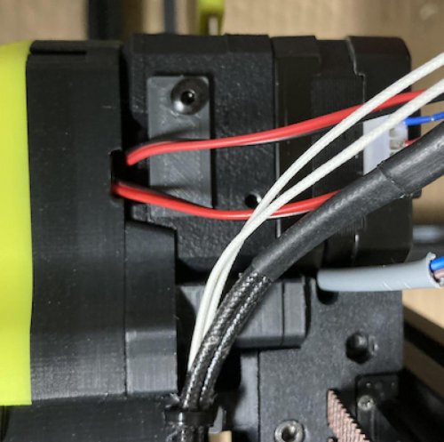
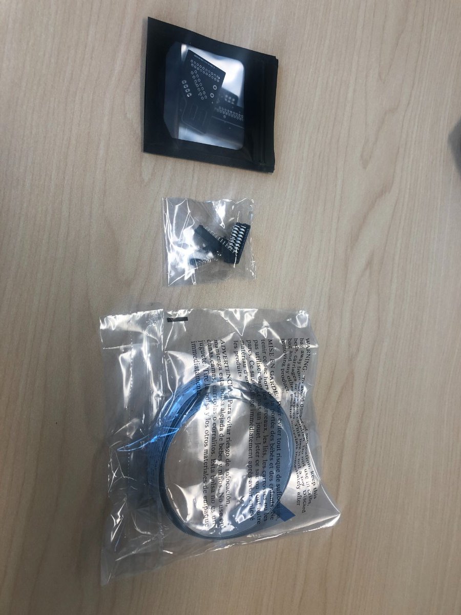
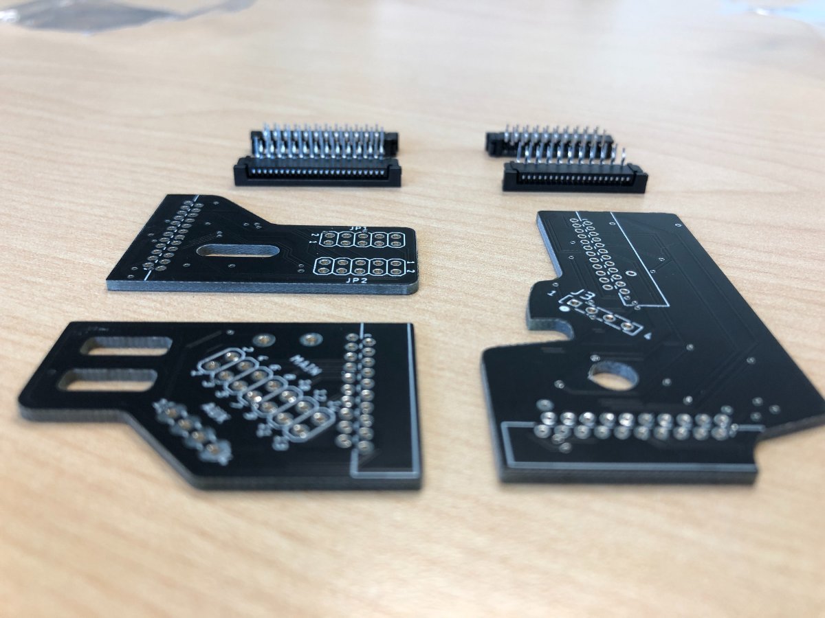
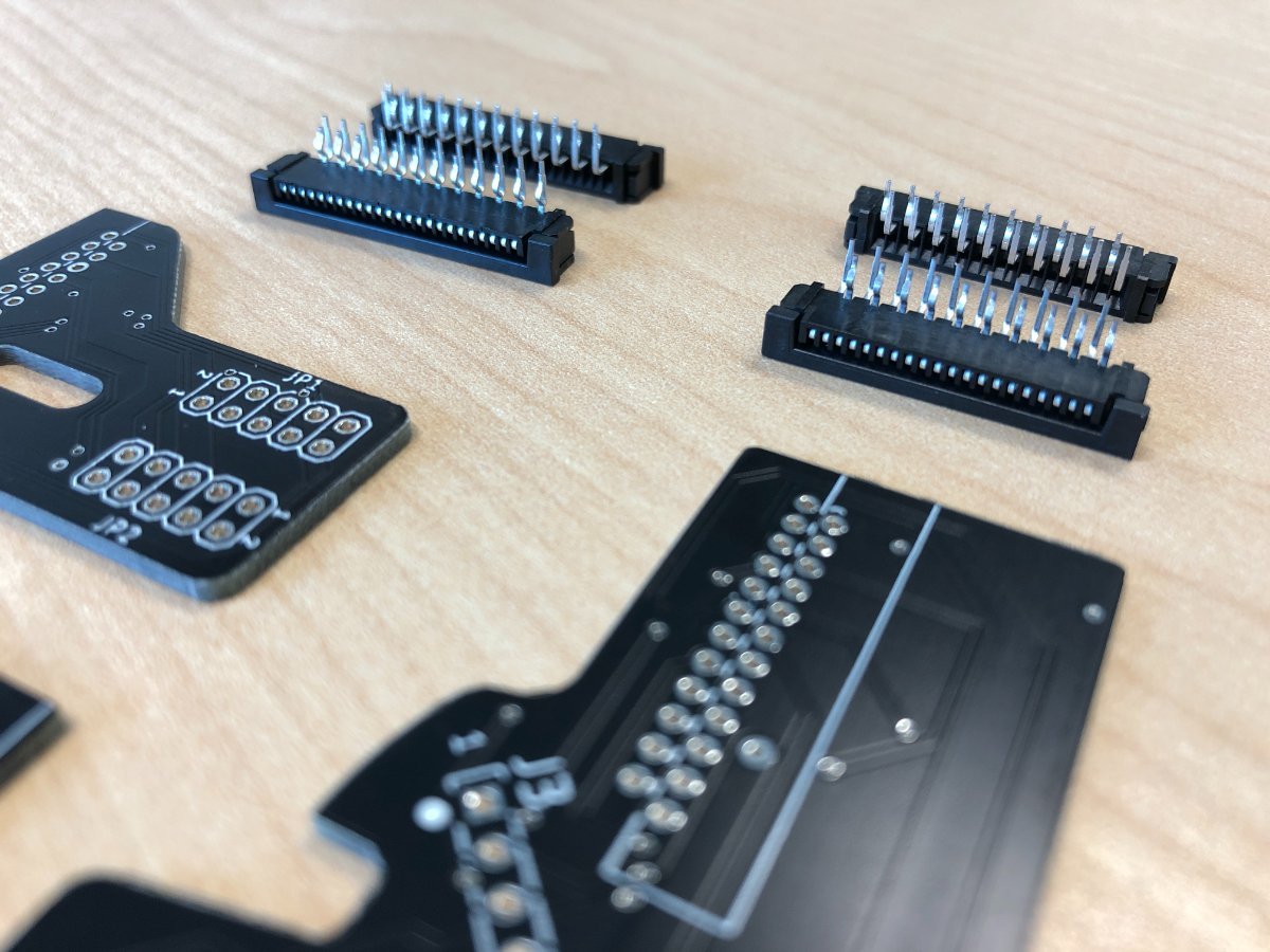
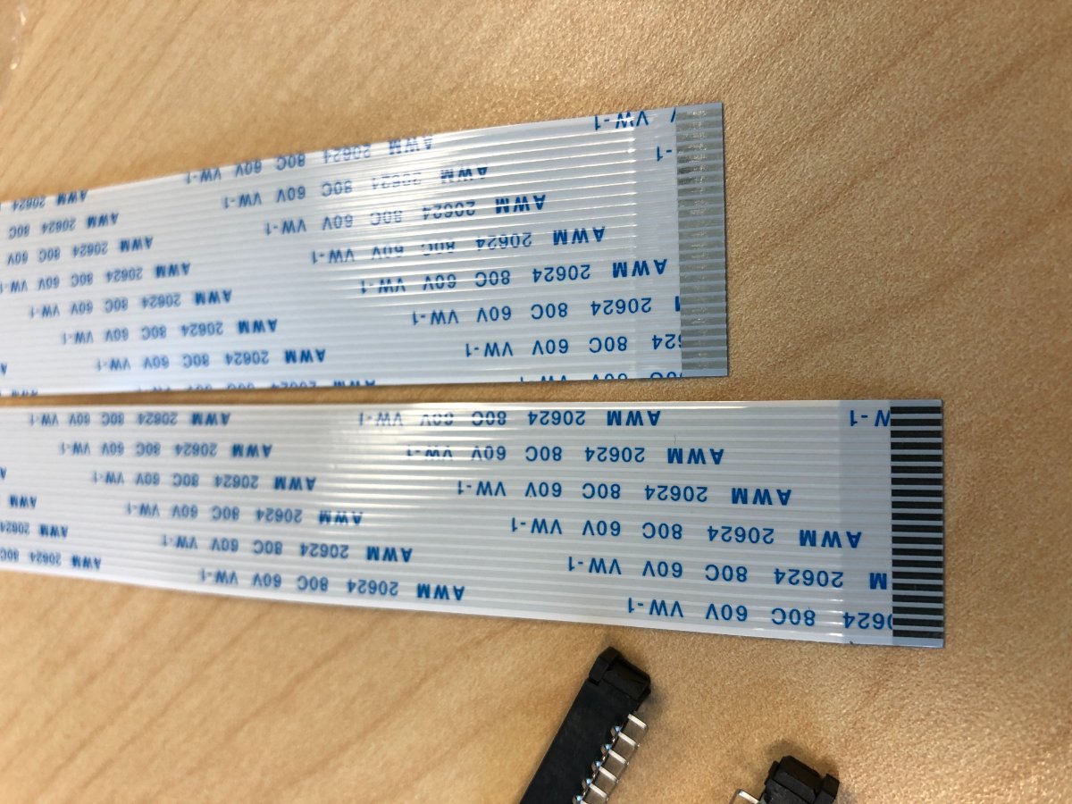
I am not affiliated with SchmidtProto in any way and am giving my honest feedback and review. FFC stands for "Flexible Flat Cables" I just received my Voron FFC Mod parts in the mail 4 days after ordering it, and I am excited to get use this on my Fystec kit opposed to using the included drag chains. The PCB appear to be super high quality and came package neatly and safely in separate packaging in a sturdy shipping box. I am really interested in how this works for a few reasons, obviously weight and wear will be different opposed to the standard umbilical, but also because I have a Dremel3D45 that has over 500 hours and it too uses FFC. Seller's FAQ With the recent release of Voron Trident, will this kit be compatible? Yes, this kit will work with the Trident just as well as the 2.4. Does this kit come with a 'Toolhead' PCB? Yes, this is intrinsic to the mod. There are 3 PCBs total. One at the Z/Y axis junction, one at the X/Y axis and one at the Toolhead. The toolhead PCB can be directly soldered to or used with 0.1" header pins/connectors. Do I need reflow or special soldering equipment? No, soldering is all through hole and any standard iron with a conical tip will work great. If you are interested, I was able t purchase the item straight from SchmidtProto. https://www.schmidtproto.com/shop
-
Version 2021.09.22
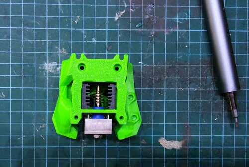
2,405 downloads
AB-BN-30 This mod is my latest iteration on improving the afterburner hotend. The naming convention is not hard: AfterBurner BadNoob version 30 Disclaimer: It is your printer. If you do this and something breaks or if someone gets hurt, it is fully your responsibility. I take no responsibility. Special thanks I want to say Thank You to the Voron design team. I've really enjoyed learning from you. Thank you for sharing your files, criticism, advice, and support. Additional thanks to Yellowfish, Long, Greg3D and all the fearless people that took time to help me along the way. BOM This is replacement to the stock afterburner, the required screws are ones you will just reuse from your existing afterburner. The main thing you will need to purchase is a 5015 blower fan. You will then have to mutilate the fan by cutting off the mounting ears. If this seems daunting to you, stop now. *Optional de-earing tool ("dearing tool") 1 M3x0.5 heat set insert 1 M3x0.5x16 SHCS For the mod itself: 4x M3x0.5 heat set inserts The usual screws used in Afterburner 2.4 1 5015 blower fan (Sunon's 12volt MF50151VX-B00U-A99, SanAce B52, or Delta BFB0524HH 24v fan are recommended) Note that sunon specifically states to NOT PWM this fan. I have been doing so for months and 10's of kilograms of pushed plastic without issue, but its important to state here. for fan advice, look for a fan with a high static head (above .7 inches H2O) and a high max flow (5 CFM ) The SoundOriginal 24v fans from Amazon also appear to do well. The following fans have been tested but are not as good in this application. they may work OK for abs, but not PLA or high speed abs: Sunon MF50152V1 (the last digit here is "speed" and 1 is a much lower speed than the MF50151VX Winsinn Hondaly Mechatronics What does it do, and why should I do this mod? This version of the afterburner fan and duct is a drop in replacement to the spec 2.4 and 1.8 afterburners. It replaces the 4020 blower with a far more powerful 5015 blower. Compared to the spec 2.4 afterburner, v24 improves the following: * Better part cooling for both ABS and PLA filaments * Fewer jams caused by heat creep * Very resistant to melting ducts * Better left-right balance * Cleaner airflow for better overhangs CHANGE Log Added support for Zodiac BMO and BMS Removed support for Slice. Added step file for AB-BN-30 Added support for Phaetus BMS and Phaetus BMO hotend Release to VoronUsers In AB BN 28 and 29, we moved to a single piece front. This has a few advantages, but it appears there may be an issue causing hotend fan failures by stressing the 4010 fan at a weak point in its housing. The issue is fixed in AB-BN-30_fan_front.stl\ I also made some slight changes to focus the part cooling flow for the dragon toolhead only. I didn't see much difference from this, so I did not migrate these changes to Mosquito or E3DV6. I just did AB-BN-xx!...why should I move to the current version? If you are using AB-BN-28 or 29, I recommend you update the fan front piece. Performance wise, ab-bn-25 is nearly identical to -30, but there are some changes. Compared to the version (AB-BN-25): Better wire management Single piece front is stiffer 4010 moved slightly to make it easier to remove hotend without removing fans Better fit (fixed the spacer to 6.6 mm) Fixed the back of the mosquito hotend. Changes made since -25 by part: Fan_front- 100%redo from -25. improved printability, standardized walls at 1.2 mm or greater. visually redone to eliminate "intake duct" or "kenny" appearance. Incorporated 4010 fan into a single piece unit. lower half matched to the hotend-front profile. fixed issue in 28,29 with 4010 fan carrier. Fan_back- 100% redo from -25. changed tabs to fit with the front. Spring- reduced size to fit Spacer-reduced thickness to 6.6mm Hotend-E3Dv6-front, Hotend-Dragon-front, Hotend-Mos-front: Reduced and adjusted stator to flow better with relocated 4010 fan, thickened walls at important points. Hotend-E3D-Dragon-back- NO CHANGES FROM -25 Hotend-Mos-back- adjusted to line up with Mos-front better. Print Settings: I use the standard Voron print settings, but with 30% infill. I have gone as low as 0% on the hotend_front, these parts don't get a lot of stress. I also use Hilbert curve for top and bottom patterns. ABS is recommended, but these have been printed in ABS+ and PETG as well: 0.4 mm Nozzle 0.2 mm layer height 30% infill no supports 4 vertical shells 5 solid layers top and bottom What files need to be printed? Everyone will need: AB-BN-30_fan_front.stl AB-BN-30_fan_back.stl AB-BN-28_spring.stl AB-BN-28_spacer.stl Depending on your hotend you will need: Phaetus BMS: AB-BN-30_Hotend-Phaetus_BMS-front.stl AB-BN-30_Hotend-Phaetus_BMS-back.stl Phaetus BMO: AB-BN-30_Hotend-Phaetus_BMO-front.stl AB-BN-30_Hotend-Phaetus_BMO-back.stl Zodiac BMS: AB-BN-30_Hotend-Zodiac_BMS-front.stl AB-BN-30_Hotend-Zodiac_BMS-back.stl Zodiac BMO: AB-BN-30_Hotend-Zodiac_BMO-front.stl AB-BN-30_Hotend-Zodiac_BMO-back.stl E3DV6: AB-BN-28_Hotend-E3Dv6-front.stl AB-BN-28_Hotend-E3Dv6-back.stl Dragon (high flow and regular): AB-BN-30_Hotend-Dragon-front.stl AB-BN-28_Hotend-Dragon-back.stl Mosquito (high flow and regular): ANNOUNCEMENT I no longer support the hotends from Slice Engineering. I find their business practices to be inconsistent with my philosophy. It makes no sense for me to put time and effort into designing a toolhead so that they can get a better price for their overreaching patent claims. My designs are all open source. Slice is free to take them and adapt them their own damn selves, but I'm not lifting another finger to help them. Assembly: This is the fan after modification Step 1: Cut the ears off the 5015 fan. In order to fit, you must cut the ears (mounting tabs) off the 5015 fan, and take off the top cover. The ears can be cut with diagonal clippers, hacksaw, bread knife, belt sander...whatever you have at hand. Just make it look like the image above. If you cut too much it's probably fine, as long as you don't damage the turbine. I have included stls for an optional de-earing tool (5015-deearing-tool and 5015-deearing-tool-b). The tool is meant as a handle and guide to saw off the ears. The tool fits around the ear and its edge can be used as a saw guide to cut the mounting ear off. Step 2: Fan test fit. The fan fits into AB-BN-30_fan_front. We have learned that different "5015" fans have very different shapes. AB-BN is designed to allow for adjustment for your fan. Here's how: Test fit the fan in AB-BN-30_fan_front. Looking at it from the front, move the fan around to center the turbine blades. You may need to trim your fan housing a little more. Once the fan is centered, turn this over and note where you need to add shims between AB-BN-30_fan_front and the fan. To shim this I recommend vhb tape. Step 3: Spring THEN Fan Once you have your shims in the right spots, remove the fan and install the printed leaf spring (AB-BN-28_spring) into fan front. The little circle tab should be cut off, it's an integral print support only. Don't forget to remove the integral print support Insert fan into 5015 front and secure with fan spring. The spring bends back to hold the fan in place. Step 4: Insert the 4010 fan in the AB-BN-30_fan_front. This is a tight fit by design. Step 5: Carefully route the wires, they will exit the 5015 back. tip: use a dab of hotglue on the fan housing to secure the wires to the fan housing fans wiring Step 6: Insert the tabs from the AB-BN-30_fan_back into the front and take the wires out through the cutout. mounting the fan spacer between extruder and fan assy Step 7: Assemble with the spacer as shown and secure to the extruder body. excess wire may be stored in the spacer Assemble the hotend as usual. ENJOY! Please drop me a DM if you find this mod useful or you have an idea to change.